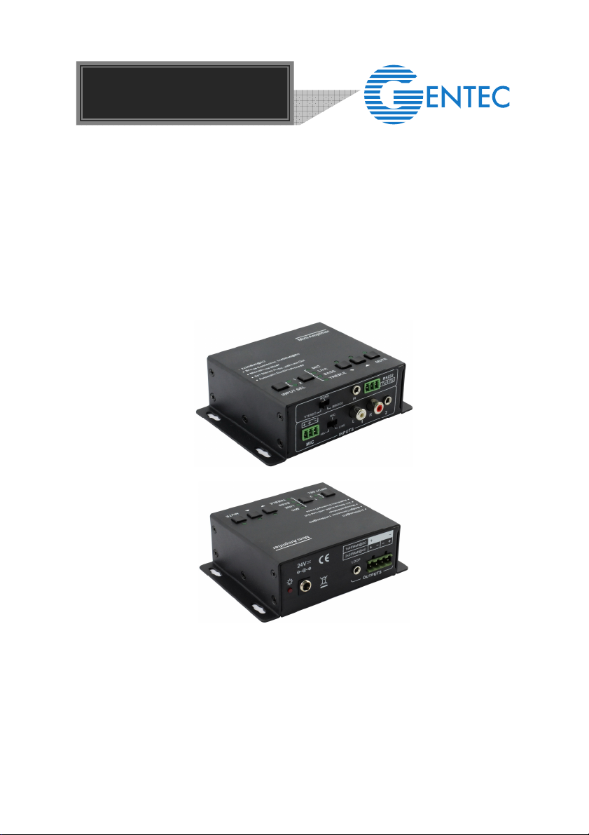
Mini Digital Amplifier
1
1. Introduction
1.1. Introduction to Mini Digital Amplifier
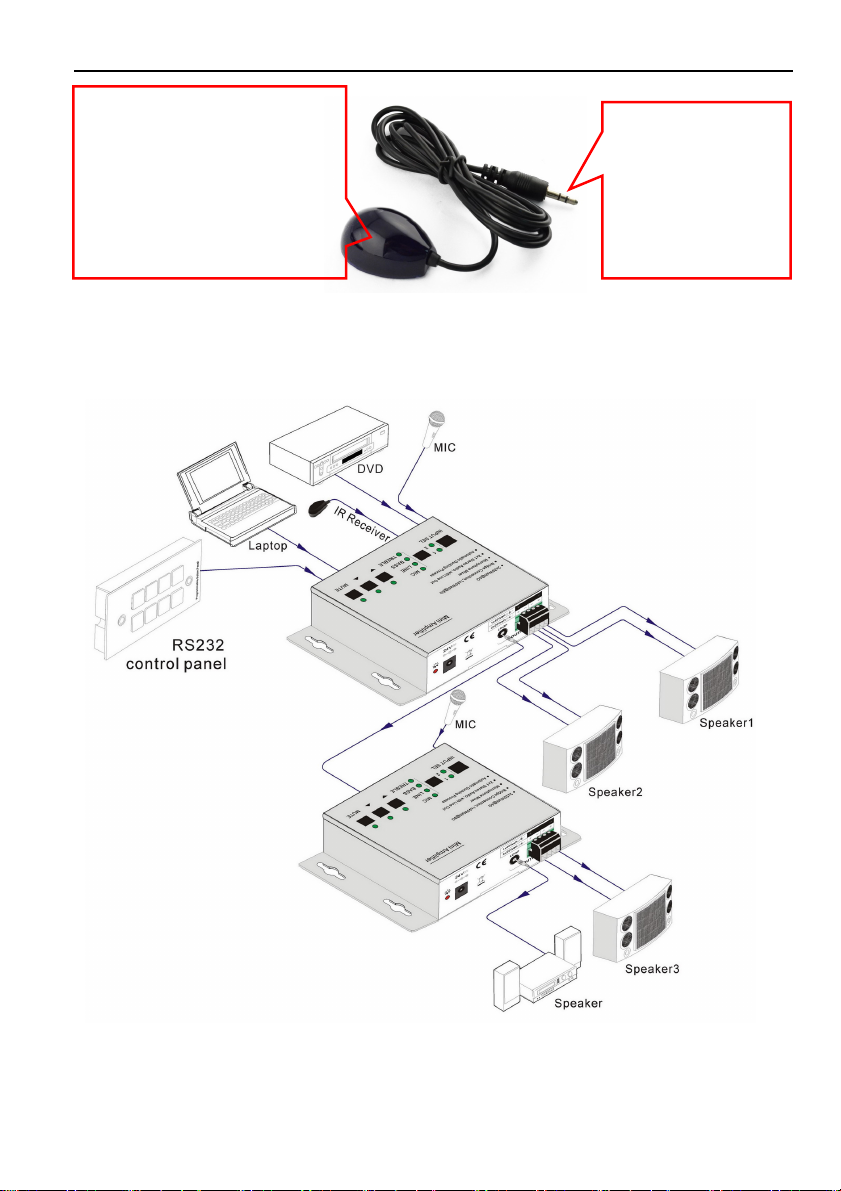
The Mini Digital Amplifier is a compact-size digital amplifier (Class-D) with 3 inputs (2
line in and 1 balanced MIC). It is integrated with powerful functions, including bridge
connection, dual-mono, EQ control, microphone mixer etc.
It has a good application in different places, including classroom, small meeting room,
lecture hall, bar, pub etc.
1.2. Features
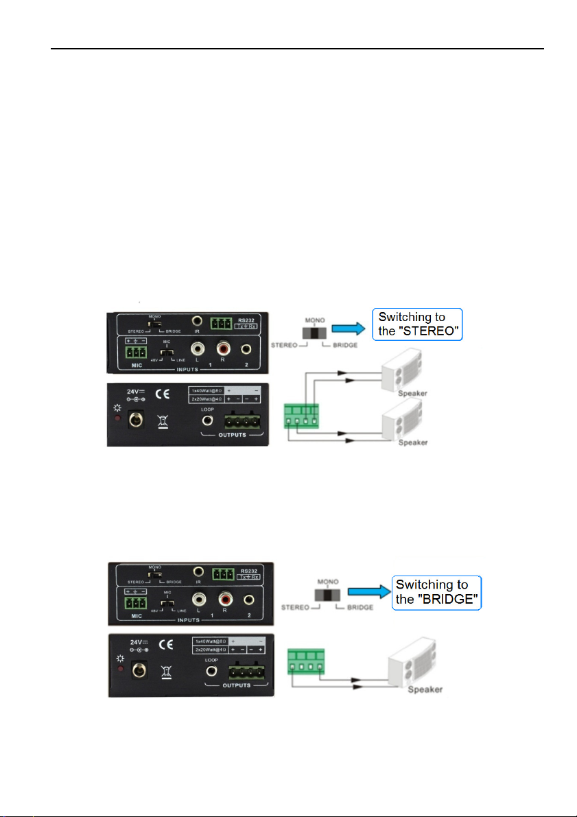
2x20Watt@4Ohm as the default amplifier output.
Bridge connection function. User can switch the Mini Digital Amplifier to be
1x40Watt@8Ohm by bridge connection.
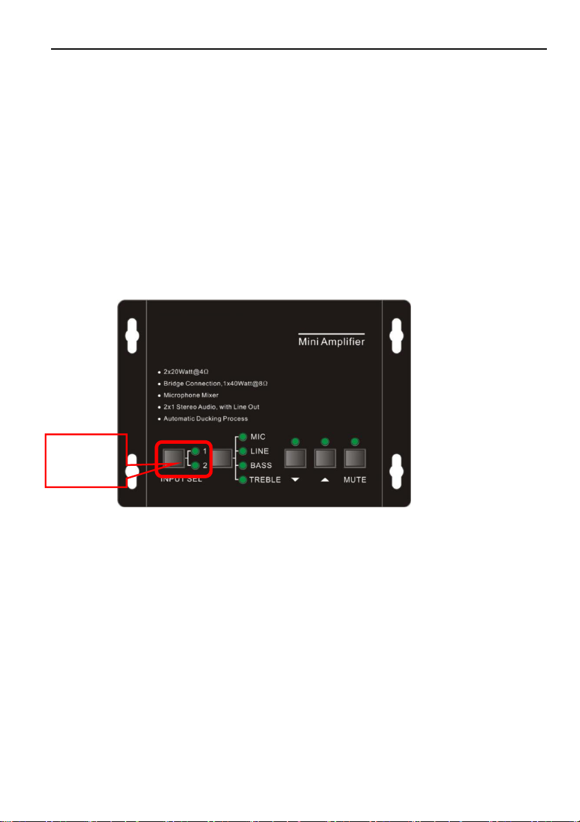
Two stereo audio inputs, switchable by button, IR remote & RS232.
Volume/Bass/Treble controllable by buttons IR remote & RS232.
MIC port can support balance/unbalance signal, suppress the external noise
effectively.
Line audio output at 3.5mm jack, with volume controllable.
Dual-mono function. User can sum up the stereo audio to two times mono audio.
MIC mixer function. The microphone will be mixed to the line audio output, and be
controlled separately.
MIC input supports 48V phantom power, dynamic MIC and wireless MIC.
Auto noise gate. It keeps detecting the audio and MIC input, will mute the output
when there is no input.
Ultra low inrush current, no need for power sequencing. This allows multiple Mini
Digital Amplifier to be powered on simultaneously without overloading power
circuits.
Convection cooler, fan is not needed.
Antistatic case design: providing good protection for long-term and stable
performance.
1.3. Package List
1 x Mini Digital Amplifier (The mounting ears and Mini Digital Amplifier are as a
whole.)
2 x Pluggable Terminal Blocks
1 x RS232 Cable
1 x Power Adapter
1 x Power Cord