Gentner SPH10 User manual

Perfect Communication through Technology, Service, and Education.
TM
Installation & Operation Manual
Analog Telephone Hybrid
SPH10

SPH10 Installation and Operation Manual
Gentner Part No. 800-012-201
April 2000 (Re . 2.0)
© 2000 Gentner Communications Corporation. All rights reserved. Gentner Communications Corporation reserves
specification privileges. Information in this manual is subject to change without notice or obligation.
This e uipment complies with the re uirements of the EU guidelines:
89/336/EEC “Electromagnetic Compatibility”
73/23/EEC “Electrical operating material for use within specific voltage limits”
1999/5/EC “Radio e uipment and telecommunications e uipment”
Conformity of the e uipment with the above guidelines is attested by the CE mark.
The connection ports on the SPH10 are to be used as follows:
Power Connection to the provided power cord
Remote Connection to external controlling and status device(s)
Monitor Out Connection to external speaker 8 ohm
Send In Connection to audio output devices
Caller Out Connection to audio input devices
Aux Out Connection to audio input devices
Telco Line Connection to telephone line
Telco Set Connection to telephone set

TECHNICAL SUPPORT: 1.800.283.5936 (USA) OR 1.801.974.3760
Introduction . . . . . . . . . . . . . . . . . . . . . . . . . . . . . . . . . .3
What's In This Manual . . . . . . . . . . . . . . . . . . . . . . . . . . . . . . . . . . . . . . . . . . . . . . .4
Technical Support . . . . . . . . . . . . . . . . . . . . . . . . . . . . . . . . . . . . . . . . . . . . . . . . . .4
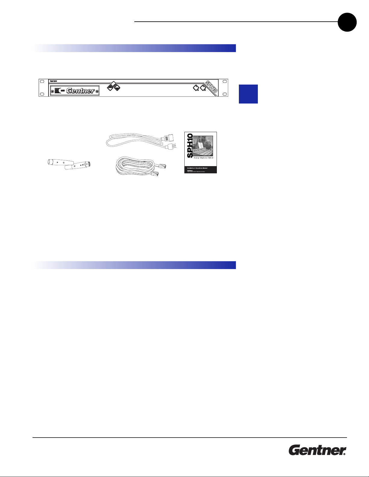
Unpacking . . . . . . . . . . . . . . . . . . . . . . . . . . . . . . . . . . . . . . . . . . . . . . . . . . . . . . . . .5
Product Registration . . . . . . . . . . . . . . . . . . . . . . . . . . . . . . . . . . . . . . . . . . . . . . . .5
O er iew . . . . . . . . . . . . . . . . . . . . . . . . . . . . . . . . . . .7
About the SPH10 . . . . . . . . . . . . . . . . . . . . . . . . . . . . . . . . . . . . . . . . . . . . . . . . . . .7
Product Description . . . . . . . . . . . . . . . . . . . . . . . . . . . . . . . . . . . . . . . . . . . . . . . .8
Front-Panel Controls . . . . . . . . . . . . . . . . . . . . . . . . . . . . . . . . . . . . . . . . . .8
Rear-Panel Connectors . . . . . . . . . . . . . . . . . . . . . . . . . . . . . . . . . . . . . . .9
Installation . . . . . . . . . . . . . . . . . . . . . . . . . . . . . . . . . .11
Before You Install . . . . . . . . . . . . . . . . . . . . . . . . . . . . . . . . . . . . . . . . . . . . . . . . . . .11
Power Re uirements . . . . . . . . . . . . . . . . . . . . . . . . . . . . . . . . . . . . . . . . .11
Telephone Line Re uirements . . . . . . . . . . . . . . . . . . . . . . . . . . . . . . . .11
Installation . . . . . . . . . . . . . . . . . . . . . . . . . . . . . . . . . . . . . . . . . . . . . . . . . . . . . . . . .11
Mix-Minus . . . . . . . . . . . . . . . . . . . . . . . . . . . . . . . . . . . . . . . . . . . . . . . . . . . . . . . . . .13
Calibration . . . . . . . . . . . . . . . . . . . . . . . . . . . . . . . . . . . . . . . . . . . . . . . . . . . . . . . . .17
DIP Switches . . . . . . . . . . . . . . . . . . . . . . . . . . . . . . . . . . . . . . . . . . . . . . . . . .17
Trim Pots . . . . . . . . . . . . . . . . . . . . . . . . . . . . . . . . . . . . . . . . . . . . . . . . . . . . .17
Operation . . . . . . . . . . . . . . . . . . . . . . . . . . . . . . . . . . .19
Front Panel . . . . . . . . . . . . . . . . . . . . . . . . . . . . . . . . . . . . . . . . . . . . . . . . . . . . . . . .19
Using the Hybrid . . . . . . . . . . . . . . . . . . . . . . . . . . . . . . . . . . . . . . . . . . . . . .19
Using the Telephone Set . . . . . . . . . . . . . . . . . . . . . . . . . . . . . . . . . . . . . .19
Switching a Call from the Set to the Hybrid . . . . . . . . . . . . . . . . . . . . .19
Switching a Call from the Hybrid to the Set . . . . . . . . . . . . . . . . . . . . .19
Disconnecting a Call . . . . . . . . . . . . . . . . . . . . . . . . . . . . . . . . . . . . . . . . . .19
Placing a Call . . . . . . . . . . . . . . . . . . . . . . . . . . . . . . . . . . . . . . . . . . . . . . . . .20
Adjusting the Monitor Output Level . . . . . . . . . . . . . . . . . . . . . . . . . . . .20
Remote Control Option . . . . . . . . . . . . . . . . . . . . . . . . . . . . . . . . . . . . . . .20
Recording Option . . . . . . . . . . . . . . . . . . . . . . . . . . . . . . . . . . . . . . . . . . . .20
able of Contents
T

TECHNICAL SUPPORT: 1.800.283-5936 (USA) OR 1.801.974.3760
TABLE OF CONTENTS
2
Appendices . . . . . . . . . . . . . . . . . . . . . . . . . . . . . . . . .21
Appendix A: Specifications . . . . . . . . . . . . . . . . . . . . . . . . . . . . . . . . . . . . . . . . .21
Dimensions . . . . . . . . . . . . . . . . . . . . . . . . . . . . . . . . . . . . . . . . . . . . . . . . . .21
Weight . . . . . . . . . . . . . . . . . . . . . . . . . . . . . . . . . . . . . . . . . . . . . . . . . . . . . . .21
Operating Temperature . . . . . . . . . . . . . . . . . . . . . . . . . . . . . . . . . . . . . . .21
Humidity . . . . . . . . . . . . . . . . . . . . . . . . . . . . . . . . . . . . . . . . . . . . . . . . . . . . .21
Front Panel Controls . . . . . . . . . . . . . . . . . . . . . . . . . . . . . . . . . . . . . . . . . .21
Rear Panel Connectors . . . . . . . . . . . . . . . . . . . . . . . . . . . . . . . . . . . . . . .21
Telephone Transmit . . . . . . . . . . . . . . . . . . . . . . . . . . . . . . . . . . . . . . . . . . .22
Telephone Receive . . . . . . . . . . . . . . . . . . . . . . . . . . . . . . . . . . . . . . . . . . .22
Null . . . . . . . . . . . . . . . . . . . . . . . . . . . . . . . . . . . . . . . . . . . . . . . . . . . . . . . . . . .22
Appendix B: Connector Pinouts . . . . . . . . . . . . . . . . . . . . . . . . . . . . . . . . . . . . .23
Appendix C: Block Diagram . . . . . . . . . . . . . . . . . . . . . . . . . . . . . . . . . . . . . . . . .24
Appendix D: Warranty & Compliance . . . . . . . . . . . . . . . . . . . . . . . . . . . . . . . .25
Warranty . . . . . . . . . . . . . . . . . . . . . . . . . . . . . . . . . . . . . . . . . . . . . . . . . . . . .25
FCC Part 15 Compliance . . . . . . . . . . . . . . . . . . . . . . . . . . . . . . . . . . . . . .26
FCC Part 68 Compliance . . . . . . . . . . . . . . . . . . . . . . . . . . . . . . . . . . . . .26
IC Compliance . . . . . . . . . . . . . . . . . . . . . . . . . . . . . . . . . . . . . . . . . . . . . . .27
European Compliance . . . . . . . . . . . . . . . . . . . . . . . . . . . . . . . . . . . . . . . .28
Safety Information . . . . . . . . . . . . . . . . . . . . . . . . . . . . . . . . . . . . . . . . . . . .28

TECHNICAL SUPPORT: 1.800.283.5936 (USA) OR 1.801.974.3760
1
Congratulations on purchasing the SPH10 Analog Hybrid. The SPH10
interfaces telephone calls to your audio e uipment, providing superior
analog telephone integration into broadcast applications.
The SPH10 is an analog hybrid, allowing connection of a single
telephone line for on-air use. When connected in accordance to United
States, Canada, the United Kingdom, and mainland Europe compliance
standards, the SPH10 is optimal for your telephone application.
This manual gives installation, set up, and operation instructions and
helps you resolve technical problems, should any arise. For more
information, please contact Gentner Communications at the location
noted below. We welcome and encourage your comments so we can
continue to improve our products and serve your needs.
ntroduction
INTRODUCTION 3
The SPH10 is an interface
between a telephone line
and audio equipment.
Separate send and caller connec-
tions provide audio input and audio
output connections to the telephone
line. Therefore, the SPH10 is ideal
for sendin audio and/or receivin
audio from another location over a
telephone line.
✍

TECHNICAL SUPPORT: 1.800.283-5936 (USA) OR 1.801.974.3760
INTRODUCTION • WHAT’S IN THIS MANUAL
4
What’s In This
Manual The manual is divided into the following sections:
O er iew summarizes the main capabilities of the SPH10 and
describes the controls and connectors.
Installation explains how to connect SPH10 cables and how calibrate
the different controls on the unit.
Operation describes how to use the front panel controls to connect
and disconnect calls, switch calls to and from the hybrid, and use the
remote control option.
Appendices includes SPH10 specifications, connector pinouts, and
detailed warranty and compliance information.
Technical Support
For additional help on how to install, set up, operate or to obtain repair
procedures and schematics for the SPH10, please contact Gentner
technical support.
Telephone: 1.800.283.5936 (USA) or 1.801.974.3760
Fax: 1.801.974.3638
E-mail: tech1@gentner.com
Web site: www.gentner.com
Sales and Customer Ser ice
Telephone: 1.800.945.7730 (USA) or 1.801.975.7200
Fax: 1.800.933.5107 (USA) or 1.801.977.0087
E-mail: bcastinfo@gentner.com
Gentner Communications Corporation
1825 Research Way, Salt Lake City, UT 84119
Technical Support

TECHNICAL SUPPORT: 1.800.283.5936 (USA) OR 1.801.974.3760
INTRODUCTION • UNPACKING 5
Ensure that the following items were received with your shipment:
Please register your SPH10 online by visiting Gentner Technical Support
on the World Wide Web at www.gentner.com. When your product is
properly registered, Gentner Communications can better serve you
should you re uire technical assistance or want to receive upgrades or
new product information.
SPH10
Part 910-012-201 (Domesti )
Part 910-012-203 (Pan European)
Part 910-012-204 (Australian)
AC Power Cord
Part 699-150-006
12-foot Modular
Telephone Cable
Part 830-000-012
XLRs
1 male, 1 female
Parts 664-600-003
and 664-500-003
SPH10 Installation and
Operations Manual
Part 800-012-201
4 Ra k Mount Cups
Part 684-400-001
4 Ra k Mount S rews
Part 681-400-001
Unpacking
Gentner Communications
is not responsible for
product dama e incurred
durin shipment. You must make
claims directly with the carrier.
Inspect your shipment carefully for
obvious si ns of dama e. If the
shipment appears to be dama ed,
retain the ori inal boxes and
packin material for inspection by
the carrier. Contact your carrier
immediately.
!
Product
Registration

TECHNICAL SUPPORT: 1.800.283-5936 (USA) OR 1.801.974.3760
OVERVIEW • UNPACKING
6

TECHNICAL SUPPORT: 1.800.283.5936 (USA) OR 1.801.974.3760
2
• Separate audio send input and caller output level adjustments
• Analog filter minimizes hum and Central Office switching noise
•Built-in 1W monitor amp with front panel push button volume control
•On/Off control via front panel and rear-panel remote connection
• Analog receive filter for telephone line-noise reduction
• Professionally balanced XLR inputs and outputs
• Auxiliary XLR output for recording both send and caller audio
• Simple installation and operation
• Selectable mic/line input
Overview
About the SPH10
OVERVIEW • ABOUT THE SPH10 7

TECHNICAL SUPPORT: 1.800.283-5936 (USA) OR 1.801.974.3760
OVERVIEW • PRODUCT DESCRIPTION
8
The SPH10 provides superior analog telephone integration into
broadcast applications. The SPH10 also provides easy on/off control as
well as level adjustment of the Monitor Out jack from the front panel.
Front-Panel Controls
The SPH10 front-panel controls perform the following functions:
1. Send In. This trim pot adjusts the level of audio sent to the phone
line via the Send In jack. At its midpoint (6 o’clock position), the trim
pot is set for nominal send level (0dBm).
2. Aux Send. This trim pot adjusts the level of the auxiliary send audio
coming from the remote connector input and going onto the
telephone line to the caller. At its midpoint (6 o’clock position), the
trim pot is set for nominal level (0dBm).
3. Aux Out. This trim pot adjusts the level of the audio at the Aux Out
jack which includes both the caller audio and the send audio. At its
midpoint (6 o’clock position), the trim pot is set for nominal level
(0dBm).
4. Caller Out. This trim pot adjusts the caller audio level to the user’s
e uipment. At its midpoint (6 o’clock position), the trim pot is set for
nominal caller level (0dBm).
5. DIP Switches. Three active dip switches (2, 3, and 4) configure
the SPH10 system. Individual switch functions are defined in
Calibration (page 17).
6. Volume. These up/down buttons control the audio level of the
Monitor Out speaker amplifier. Pressing once changes the level by
1dB. Pressing and holding the buttons sweeps the level up or down.
7. On LED. This LED indicates the SPH10 has connected with the
telephone line. The LED illuminates green when the hybrid is on and
flashes green when the phone line is ringing.
SPH10 front-panel controls
1 2 3 46 9 10
78
5
Product Description

TECHNICAL SUPPORT: 1.800.283.5936 (USA) OR 1.801.974.3760
OVERVIEW • PRODUCT DESCRIPTION 9
8. Off LED. This LED indicates the SPH10 is not connected to the
telephone line. The LED illuminates red when the hybrid is off.
9. On. The On button connects the hybrid to the telephone line. When
the hybrid is on, the Set jack is disconnected from the telephone
line. Therefore, if a telephone set is connected to the Set jack, it will
become inactive when the hybrid is on.
10. Off. The Off button disconnects the hybrid from the telephone line
and mutes all audio going to and from the telephone line. When the
hybrid is off, the Set jack is connected to the telephone line
which makes a connected telephone set active.
Rear-Panel Connectors
1.Power. The AC power cord input is a IEC type connector
allowing use of premolded domestic US power cords as well as
various other premolded international power cords.
2. Remote. This DB25 female connector provides remote control and
status of the hybrid. Unbalanced Send in, Caller out ,and Aux out
audio are also available at the remote connector. See Appendix C:
Connector Pinouts (page 23).
3. Monitor Out. This 1/4" jack is a speaker connection for
monitoring the caller audio signal. The monitor output provides 1W
into an 8 Ohm speaker.
4. Send In. This balanced, female, 3-pin XLR input receives audio
from the source (microphone or mixer) and sends it to the caller.
The send audio must not include the caller’s audio signal. See Mix-
Minus (page 13).
1 2 3 4 6 785
SEND IN CALLER OUT AUX OUT
If usin a sin le
microphone that needs
phantom power to
operate, you must supply this
power to the microphone.
The SPH10 does not supply
phantom power.
✍
SPH10 rear-panel connectors

TECHNICAL SUPPORT: 1.800.283-5936 (USA) OR 1.801.974.3760
10
5. Caller Out. This balanced, male, 3-pin XLR output contains
the audio from the telphone line (the caller's voice).
6. Aux Out. This balanced, male, 3-pin XLR output contains a mix
of the Send In Audio and the Caller Out Audio. This connector
can feed a recording device to record both the caller and send
audio.
7. Line. This RJ11 connector provides connection of the
telephone line to the SPH10 hybrid.
8. Set. This RJ11 connector allows connection to a standard
analog telephone set. The telephone line is present at this
connector when the SPH10 is Off. The telephone line is not
present at this connector when the hybrid is On.
OVERVIEW • PRODUCT DESCRIPTION

TECHNICAL SUPPORT: 1.800.283.5936 (USA) OR 1.801.974.3760
3
Power Requirements
The SPH10 automatically adjusts to accept voltage re uirements of
100–240VAC, 50/60Hz.
Telephone Line Requirements
The SPH10 operates on a standard POTS (plain old telephone service)
analog telephone line or an analog extension from a PBX via a standard
RJ11C modular jack.
nstallation
Before You Install
INSTALLATION • BEFORE YOU INSTALL 11
Installation
The SPH10 is designed for easy installation and setup. All necessary
interface connections are made through rear-panel connectors. Refer
to SPH10 Rear-Panel Connectors (page 9) for a description and
placement of each of the connections you will be making. Each
connection is numbered for easy identification.
The diagram below illustrates a typical SPH10 interconnection.
Re ord Input
Console In
Mix-Minus Out
Telephone Line Telephone Set
SEND IN CALLER OUT AUX OUT
Some telephone lines
do not provide battery
volta e (dry line, no DC
offset volta e). If yours does
not, the SPH10 may be
confi ured by qualified
personnel for dry line operation.
Please contact Gentner
Technical Support for details.
✍

TECHNICAL SUPPORT: 1.800.283-5936 (USA) OR 1.801.974.3760
INSTALLATION • INSTALLATION
12
To install your SPH10, make the following connections:
Power Connection
The SPH10 will operate at any power level between 100–240VAC,
50–60Hz.
Remote Control
If using a remote control for parallel control and hybrid status, use the
DB25 Remote connector. For pinouts, see Appendix C: Connector
Pinouts (page 27). The remote control connector provides remote
control and status of the hybrid. It also provides unbalanced audio
inputs and outputs.
Monitor Out
Connects an 8 Ohm speaker to this 1/4" TRS jack to monitor a 1W
amplified caller signal.
Send In
Connect the Send In female XLR jack to an output from your studio
console. Connect the audio you want the caller to hear to this audio
input. Audio coming from the console must be a mix-minus. See Mix-
Minus (page 13).
Caller Out
Connect the Caller Out male XLR jack to an input on your audio
console. This audio output contains the caller's voice.
Aux Out
Connect this male XLR jack to your recording device. This connector
contains a mix of send audio and caller audio.
Line
Plug your analog telephone line into the RJ11C Line jack.
Set
Plug your telephone set into the RJ11C Set jack.
TELCO
LINE SET
GND
GND

TECHNICAL SUPPORT: 1.800.283.5936 (USA) OR 1.801.974.3760
INSTALLATION • MIX-MINUS 13
Mix-Minus
Mix-minus is a mix of all audio being sent to the Send In jack of the
hybrid, minus the caller audio. Without a mix-minus feed from the
console, the caller audio sent to the console will be retransmitted to the
caller. This can cause hollow sounding audio and can even result in
feedback. The following are some ways to create/configure an external
mix minus feed for the SPH10 hybrid.
Using the Mic Preamp of the Hybrid
If only microphone audio is being sent to the caller, the internal
microphone preamplifier of the hybrid may be used. When doing this,
change the Send In jack from a line level input to a mic level input by
placing dip switch #4 to the on (up) position. In this configuration make
sure the microphone is not picking up the caller’s audio as it is
presented in the room by the speaker.
Speaker
Monitor Send
Mi rophone Tape Player
Telephone Set
Telephone Line
Using the Direct Mic Output of the Console
If only microphone audio is being sent to the caller, then it is possible to
use the console’s direct microphone output. Use the console direct
microphone output to provide line level microphone audio to the Send
In jack of the SPH10.
Telephone Set
Telephone Line
Tape Player/Re order
CD Player
Mi rophone
Inputs
Transmitter
Program Mix
Mix-Minus
Send Caller
Mix Output
Console/Mixer
Note: Mi rophone audio re eives
preamplifi ation from the onsole.

TECHNICAL SUPPORT: 1.800.283-5936 (USA) OR 1.801.974.3760
INSTALLATION • MIX-MINUS
14
Using a Discrete Microphone Mixer
If only microphone audio is being sent to the caller, a separate micro-
phone mixer may be used. The mic mixer will provide the mix-minus
feed for the hybrid, because its output contains no caller audio.
Telephone Set
Telephone Line
Tape Player/Re order
CD Player
Inputs
Transmitter
Program Mix
Mix-Minus
Send Caller
Mix Output
Console/Mixer
Mi Mixer
Mi rophones
SPH 10
Using an Internal Mix Bus (Telephone Module)
Many console manufacturers provide optional Telephone Hybrid
Modules for their consoles. These modules are designed to receive
audio from a hybrid and transmit audio to the hybrid. A telephone
module will create a mix-minus for the hybrid at its output.
Telephone Set
Telephone Line
Tape Player/Re order
CD Player
Mi rophone
Inputs
Transmitter
Program Mix
Mix-Minus
Send Caller
Mix Output
Console/Mixer
Note: The Telephone Module
provides a mix-minus output.

TECHNICAL SUPPORT: 1.800.283.5936 (USA) OR 1.801.974.3760
INSTALLATION • MIX-MINUS 15
Using a Separate Mix Output Bus from the Console
If the console has an extra mix output, then use this extra output to
provide a mix-minus feed for the hybrid. Simply route all audio, minus
the caller audio, to the extra output bus of the console (Output B).
Using a Separate Auxiliary Output Bus from the Console
If the console has an auxiliary output, usually called Aux Out or Aux
Send, then use this auxiliary output to provide a mix-minus feed for the
hybrid. Simply route all audio, minus the caller audio to the auxiliary
output bus of the console.
Telephone Set
Tape Player/Re order
CD Player
Mi rophone
Telephone Line
Caller
Send
Mix-Minus
Program Mix
Transmitter
Output
A
Output
B
Inputs
Console/Mixer
ON
OFF
Note: All input hannels are sele ted
to the Outputs A and B, ex ept for the
in oming aller audio. It is sele ted to
Output A only.
Transmitter
Program Mix
Mix-Minus
Send Caller
Mix
Output
Auxiliary
Output
Console/Mixer
Inputs
Telephone Line
Telephone Set
Tape Player/Re order
CD Player
Mi rophone
Note: All Input hannels have been
turned up with the auxiliary level ontrols,
with the ex eption of the In oming aller
audio. Therefore the auxiliary output ontains
all Input sour es minus the aller audio.

TECHNICAL SUPPORT: 1.800.283-5936 (USA) OR 1.801.974.3760
INSTALLATION • MIX-MINUS
16
Using the Stereo Outputs of the Console
By using the stereo outputs of the console, it is possible to create a mix-
minus for the hybrid. By panning the caller audio to the left channel
only, the caller audio is prevented from reaching the right channel
output of the console. Therefore, the right channel output is a mix-
minus, a mix of all audio minus the caller audio.
Note: The In oming aller audio is
faded to the left hannel of the onsole's
stereo output. This prevents aller audio
from being returned to the send input.
Console/Mixer
Inputs
Stereo
Output
Mi rophone
CD Player
Transmitter
Program Mix
Mix-Minus
Send Caller
Telephone Line
Telephone Set
Tape Player/Re order

TECHNICAL SUPPORT: 1.800.283.5936 (USA) OR 1.801.974.3760
INSTALLATION • CALIBRATION 17
Calibration
DIP Switches
DIP switches are “off” in the down position and “on” in the up position.
Caller Boost
DIP switch 2 adds a 6dB level boost to the caller’s audio at the Caller
Out jack. In the Off position (down), the Caller Boost is disabled. In the
On position (up), the Caller Boost is enabled.
Remote On/Off Control
DIP switch 3 allows the hybrid to work with two types of switches for
external control: momentary and latching. In the off position (down) the
On/Off control inputs respond to momentary closures to ground. This
turns the hybrid on when it receives a momentary closure on the On
control input and off when it receives a closure on the Off control input.
In the on position (up), the Off control input is disabled and the On
control input responds to a latching closure to ground. This will cause
the hybrid to turn on when the latching switch is closed to ground and
the hybrid will remain on until the closure to ground is opened. This DIP
switch setting also affects the operation of the front panel On/Off
buttons. See Appendix B (page 23) for remote control connector pinouts.
Mic/Line Select
DIP switch 4 sets the gain of the Send In jack. In the off position (down),
the input is a line level (0dB) input. In the on position (up), the input is a
mic level providing 55dB of input gain.
Trim Pots
The front panel trim pots provide level adjustments of the Send In, Aux
Send, Aux Out, and Caller Out audio connectors. Separate audio level
controls let you optimize the audio level(s) of the SPH10 to match the
audio levels re uired by the interfaced audio e uipment.
Send In Adjustment
This pot adjusts the Send In audio. Adjust this pot along with your con-
sole audio control until callers verify that the audio level they are
receiving is at a comfortable listening level.
Aux Send Adjustment
This pot adjusts the level of the auxiliary send audio at the remote
connector input. Adjust this pot along with your console audio control
until callers verify that the audio level they are receiving is at a
comfortable listening level.
SPH10 DIP switches
Momentary and latchin switches
SPH10 trim pots

TECHNICAL SUPPORT: 1.800.283-5936 (USA) OR 1.801.974.3760
INSTALLATION • CALIBRATION
18
Aux Out Adjustment
This pot adjusts the level of send and caller audio at the Aux Out jack.
Adjust this pot along with your console audio control to set the proper
level for your recording device or other external devices.
Caller Out Adjustment
This pot adjusts the Caller Out audio. Adjust this pot along with your
console audio control to set the caller’s voice/audio to a comfortable
listening level.
If you are experiencin too
much send audio in the
caller output, a null
procedure may be performed by
qualified personnel. Please contact
Gentner Technical Support for
details.
✍
Other manuals for SPH10
1
This manual suits for next models
3
Table of contents
Other Gentner Telephone manuals