4
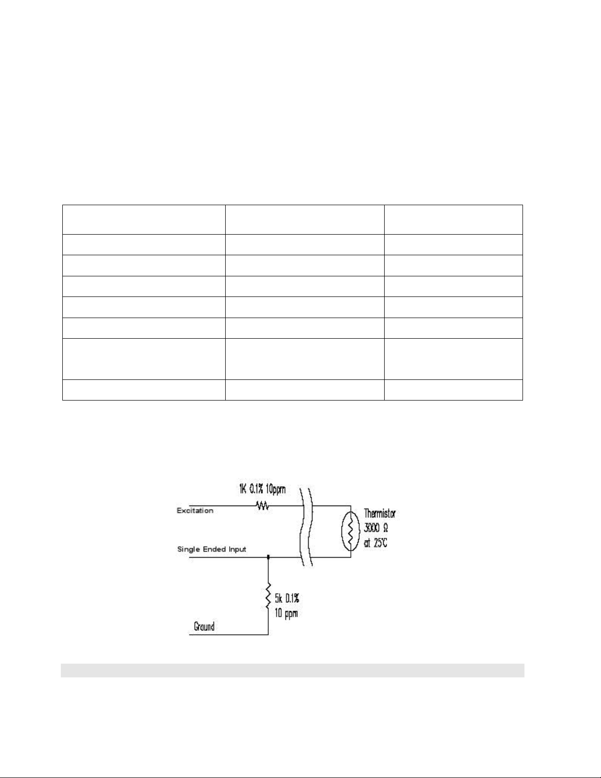
Standard Temperature Thermistor Linearization using SteinHart-Hart Log Equation
Thermistor Type: YSI 44005, Dale #1C3001-B3, Alpha #13A3001-B3
Resistance to Temperature Equation: 2.273
)()( 13
LnRCLnRBA
T
Equation B-1: Convert Thermistor Resistance to Temperature
Where: TTemperature in C
LnR Natural Log of Thermistor Resistance
A1.4051 10-3 (coefficients calculated over the 50 to +150C span)
B2.369 10-4
C1.019 10-7
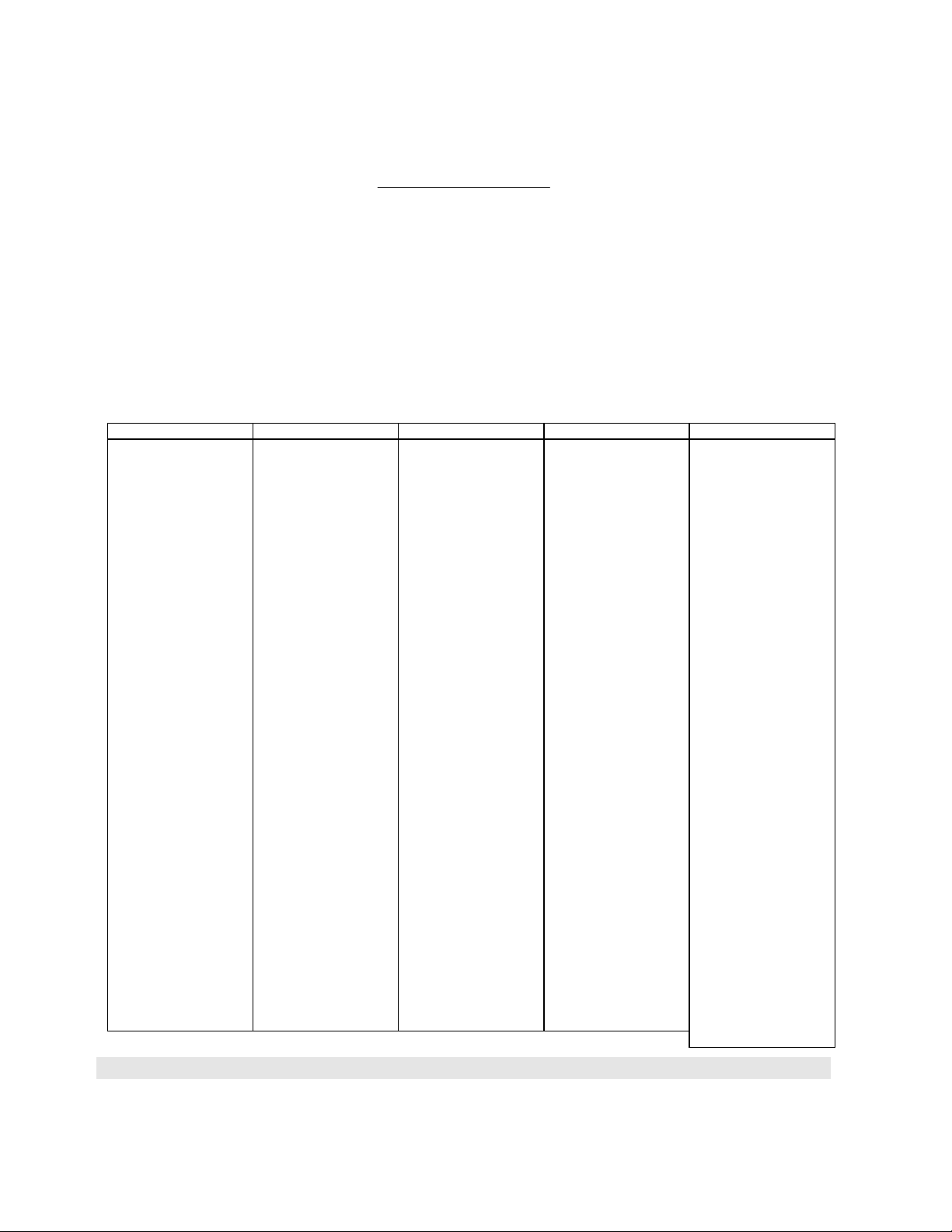
Ohms Temp Ohms Temp Ohms Temp Ohms Temp Ohms Temp
201.1
-50 16.60
-10 2417
30 525.4
70 153.2
110
187.3K -49 15.72K -9 2317 31 507.8 71 149.0 111
174.5
-48 14.90
-8 2221 32 490.9 72 145.0 112
162.7
-47 14.12
-7 2130 33 474.7 73 141.1 113
151.7K -46 13.39K -6 2042 34 459.0 74 137.2 114
141.6
-45 12.70
-5 1959 35 444.0 75 133.6 115
132.2
-44 12.05
-4 1880 36 429.5 76 130.0 116
123.5K -43 11.44K -3 1805 37 415.6 77 126.5 117
115.4
-42 10.86
-2 1733 38 402.2 78 123.2 118
107.9
-41 10.31
-1 1664 39 389.3 79 119.9 119
101.0K -40 9796 0 1598 40 376.9 80 116.8 120
94.48
-39 9310 1 1535 41 364.9 81 113.8 121
88.46
-38 8851 2 1475 42 353.4 82 110.8 122
82.87K -37 8417 3 1418 43 342.2 83 107.9 123
77.66
-36 8006 4 1363 44 331.5 84 105.2 124
72.81
-35 7618 5 1310 45 321.2 85 102.5 125
68.30K -34 7252 6 1260 46 311.3 86 99.9 126
64.09
-33 6905 7 1212 47 301.7 87 97.3 127
60.17
-32 6576 8 1167 48 292.4 88 94.9 128
56.51K -31 6265 9 1123 49 283.5 89 92.5 129
53.10
-30 5971 10 1081 50 274.9 90 90.2 130
49.91
-29 5692 11 1040 51 266.6 91 87.9 131
46.94K -28 5427 12 1002 52 258.6 92 85.7 132
44.16
-27 5177 13 965.0 53 250.9 93 83.6 133
41.56
-26 4939 14 929.6 54 243.4 94 81.6 134
39.13K -25 4714 15 895.8 55 236.2 95 79.6 135
36.86
-24 4500 16 863.3 56 229.3 96 77.6 136
34.73
-23 4297 17 832.2 57 222.6 97 75.8 137
32.74K -22 4105 18 802.3 58 216.1 98 73.9 138
30.87
-21 3922 19 773.7 59 209.8 99 72.2 139
29.13
-20 3748 20 746.3 60 203.8 100 70.4 140
27.49K -19 3583 21 719.9 61 197.9 101 68.8 141
25.95
-18 3426 22 694.7 62 192.2 102 67.1 142
24.51
-17 3277 23 670.4 63 186.8 103 65.5 143
23.16K -16 3135 24 647.1 64 181.5 104 64.0 144
21.89
-15 3000 25 624.7 65 176.4 105 62.5 145
20.70
-14 2872 26 603.3 66 171.4 106 61.1 146
19.58K -13 2750 27 582.6 67 166.7 107 59.6 147
18.52
-12 2633 28 562.8 68 162.0 108 58.3 148
17.53
-11 2523 29 543.7 69 157.6 109 56.8 149
55.6 150
Table B-1: Standard Thermistor Resistance versus Temperature