Geonics Limited EM61MK2win User manual

EM61MK2win
1745 Meyerside Drive, Mississauga, Ontario, Canada L5T 1C6
Tel: (905) 670 9580 Fax: (905) 670 9204
E-mail: [email protected]
Geonics Limited
May, 2018
Version 1.00
EM61-MK2 DATA LOGGING SYSTEM
FOR WINDOWS 10 BASED FIELD TABLET COMPUTER
OPERATING INSTRUCTIONS


Table of Contents
1. Introduction ................................................................................................ 1
1.1 Program Requirements ......................................................................... 2
1.2 Installing EM61MK2win ....................................................................... 2
1.3 Running EM61MK2win Program ........................................................... 2
1.4 Main Screen ....................................................................................... 3
Short description of Main Screen options ...............................................................3
2. Survey Setup ............................................................................................... 5
3. System Setup............................................................................................... 9
4. Set Port for GPS & Monitoring..................................................................... 13
4.1 GPS Port Setup.................................................................................. 13
4.1 Monitoring GPS Receiver Output ........................................................ 16
5. Display Options ........................................................................................ 19
6. Logging Data............................................................................................ 21
6.1 Monitoring Mode .............................................................................. 21
Description of Monitoring Mode Options.............................................................24
6.2 Stand By Mode.................................................................................. 31
6.3 Logging Mode................................................................................... 34
6.4 Stand By Mode Field Options ............................................................. 35
7. View Data Files.......................................................................................... 43
Appendix A ....................................................................................................... 47
A.1 Description of Data File in EM61MK2win Format ................................. 47
A.2 Conversion Factors............................................................................ 50
A.3 Example of File in EM61MK2win Format ............................................. 52
Appendix B ....................................................................................................... 53
B.1 Using the EM61MK2win with a GPS Receiver....................................... 53
B.2 Description of GGA and GSA Data Messages...................................... 54


1
EM61MK2win Data Logging System (DAS70-M2)
1. Introduction
e Geonics EM61MK2win Data Logging System (DAS70-win) consists of a tablet/laptop eld
computer, data logging program EM61MK2win, and associated cable to connect the computer
to the Geonics EM61-MK2 instrument. e program EM61MK2win is designed for a IBM PC
compatible computer and MS Windows 10 (or 7) operating system.
e program is prepared for the MS Windows 10 tablet Mesa2 (manufactured by Juniper Systems)
operated in the vertical mode display with the default setup. However the program can be used in
other Windows 10( or 7) based eld computers with vertical and horizontal oriented displays. e
minimum supported display resolution is 800 x 600 pixels. In case high resolution display is em-
ployed, it is advised to set fonts to 125% or 150% to increase legibility of the screen. e maximum
size of program main windows is 1024 x 762 pixels.
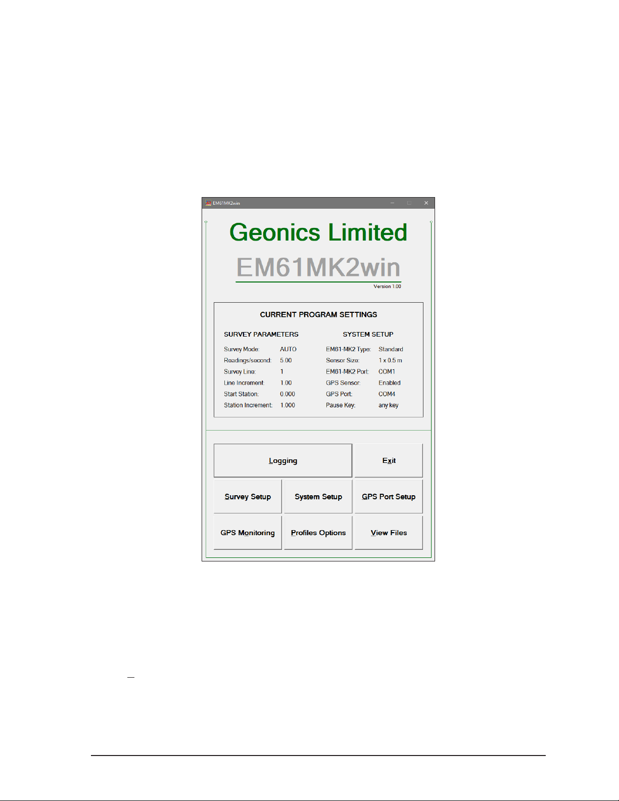
e EM61MK2win program acquires and records survey data from the EM61-MK2 system, under
the control of the operator. It also records various eld information such as survey line number (line
name), starting station, increment, comments, etc. Readings are displayed in graphic and numeric
mode. Readings are displayed in real time in mV. In addition, the program allows you to monitor
the instrument output while data is not recorded. e EM61MK2win program continuously moni-
tors the condition of the instrument battery, without leaving the program. e EM61MK2 also
provides the possibility of automatic nulling of the instrument output at any time during the survey.
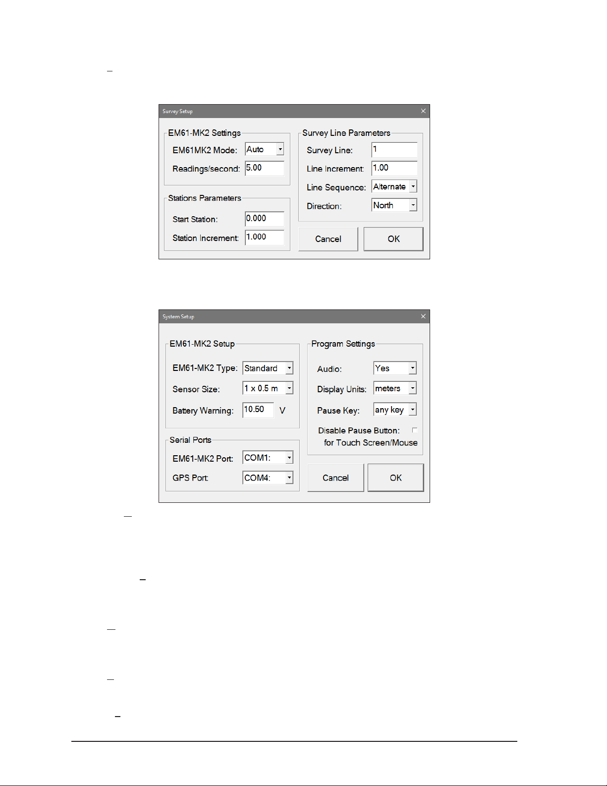
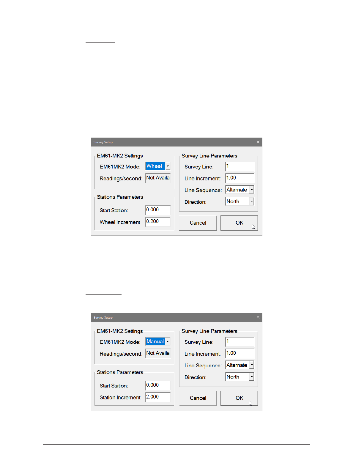
e program allows the user to set the EM61-MK2 into a specic instrument mode of operation:
AUTO, Wheel, or Manual modes. In AUTO mode readings can be automatically recorded in desired
time intervals. In WHEEL mode readings are triggered by a counter installed at the EM61-MK2
wheel assembly, and in MANUAL mode readings are triggered manually by the operator.
e program supports the standard EM61-MK2 instrument as well as EM61-MK2 High Power
unit. It also recognizes all versions of instrument rmware automatically. e program allows you
to record data while using various EM61-MK2 antenna (1 x 0.5 m, 1 x 1 m, or 0.5 x 0.5 m sensors)
and Geonics EM61HH-MK2 Hand Held sensor.
e EM61MK2win will accept NMEA-0183 compatible data from a GPS receiver directly con-
nected to an Allegro eld computer. GPS data which are embedded in the EM61MK2win data le
can be processed later in the Geonics DAT61MK2 program. e connected GPS must be able to
stream NMEA-0183 compatible messages. e EM61MK2win uses two NMEA messages GGA
and GSA. While message GGA is mandatory, the GSA string is used only to provide information
related to the GPS signal quality during data collection.
e EM61MK2win program records data together with a time stamp at each station. Data les cre-
ated with this program can be used to position a survey according to locations recorded separately
by a Global Positioning System (GPS).
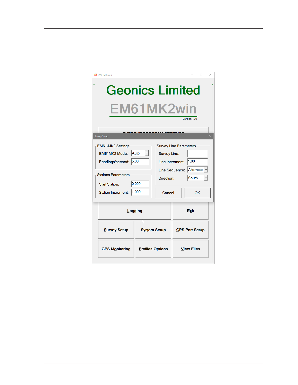
Survey setup parameters are saved in a conguration le, therefore they can be automatically used
during subsequent data collection sessions.
Data les are saved to the user selected data directory. Data le names, which can be set by the
program based on the computer clock or user specied, have extension names R61. Files can be
converted to M61 format and viewed in DAT61MK2 program. Number of readings in a data le
is limited only by the hard drive capacity, however it is strongly recommended to avoid huge data
les (i..e one to two hours long data les are adequate). e maximum speed of data collection is
approximately 18 readings per second assuming 5 Hz (or less) GPS input.

2Geonics Limited
1.1 Program Requirements
To successfully use this software, you will need :
Computer
- Mesa2 eld computer (or similar) operating under Windows 10 or 7,
- minimum 4 Gb of RAM memory,
- USB port or other mean to transfer les,
- minimum 800 x 600 pixel display resolution,
- serial Ports:
one serial port for instrument plus one serial port if directly connected GPS receiver
is to be used (USB to multiple RS-232 ports adapters can be used) or available
Bluetooth connection in serial port mode.
Geonics EM61-MK2
e EM61-MK2 instrument with associated cables (or Bluetooth option).
e EM61MK2win program may be stored on DAT61MK2 CD disk and it is available for down-
load from the Geonics web site. All necessary conguration les (with extension names .INI) are
created in your eld computer after the program is run for the rst time.
1.2 Installing EM61MK2win
e program consists of a standalone le EM61MK2win.exe, no DDLs nor other libraries are
required to run this program.
If the program le is included separately on the DAT61MK2 CD disk, or downloaded from the
web site it can be installed by copying the EM61MK2win.exe le to any directory on your hard
disk. is can be performed by using Windows Explorer.
After you run the program for the rst time it will create permanent conguration le (.INI) which
contain some of the program settings. If the above le does not exist on the default drive they will
be created with default parameters during the rst execution of the program.
e EM61MK2win data les contain extension name R61 and their base names should be limited
to 8 characters.
1.3 Running EM61MK2win Program
Start EM61MK2win by double clicking the EM61MK2win icon in the Start|Programs menu, in
Windows Explorer, or on the desktop if a shortcut was created. At the start, EM61MK2win displays
the following screen.
e EM61MK2win is a command button and dialog driven program. Command buttons can be
executed by taping (if touch screen is used) or clicking with the left mouse button, or by pressing
the indicated (underlined) character on the keyboard, or by usingTAB to scroll through the buttons
and ENTER to execute. In the Main Screen of the program Up and Down arrow keys can be also
used to scroll through the buttons.
e Main Screen appears always as the rst window after the program is started. It contains the
name of the program, its version number, and list of command buttons with available options on

3
EM61MK2win Data Logging System (DAS70-M2)
the right side. e major , left portion of the window contains information about current survey
and system settings. is section is updated in real time as soon as the program parameters are
changed in dialogs.
1.4 Main Screen
e Main Screen always appears after the program is started. It contains the name of the program,
its version number, and a list of buttons representing the available options. e EM61MK2win
Main Screen is displayed below.
ese options are selected by clicking on buttons, or from keyboard using TAB/ENTER or shortcuts
indicated by underline label characters. In case of Main Screen buttons the Down and Up arrow
keys and <ENTER> can be used as well.
Short description for each of the options follows.
Short description of Main Screen options
Logging
is option allows to monitor and log the EM61-MK2 output. e Logging screen starts
always in Monitor mode, and then after a data le is created Logging mode is available.
Monitor mode provides several options: the instrument nulling, performing Internal and
External QC coil calibration, monitoring EM61-MK2 battery level, monitoring quality
of GPS signal, etc.

4Geonics Limited
Survey Setup
e Survey Setup dialog will be displayed. All survey settings (survey line name, increments,
etc.) can be specied in this dialog.
System Setup
Dialog window that is associated with this option is used to set the instrument type, antenna
size, serial port numbers, battery warning level, and type of pause key.
Set GPS Port
e GPS Port Setup dialog allows to disable and enable GPS data acquisition. is option is
also used to set the serial port number used for GPS input and to specify necessary serial port
communication settings. GPS monitoring window can be accessed from this dialog as well.
GPS Monitoring
e program enters terminal mode and displays input from GPS. is function is very
convenient to test communication with GPS receiver and examine GPS stream type.
Display Options
e dialog which will allow you to specify colour and thickness of prole lines will appear.
is dialog provides also choice of linear or compressed amplitude used for prole display.
View Files
is option can be used to open collected data le and display survey line proles.
Exit
is option will terminate the program execution.

5
EM61MK2win Data Logging System (DAS70-M2)
2. Survey Setup
e Survey Setup dialog, presented below, contains several parameters which aect two important
procedures: instrument settings (instrument mode, frequency of data collection, etc.) and survey
geometry layout (survey line names, line spacing, start station, station increment, etc.).
To select any option click on the corresponding drop-down list box or text box, or use TAB key to
scroll to the option and then use mouse or the Down and Up keys in drop-down box (parameters
that have only a few possible options), or keyboard for text box entry.
Description of Options and Parameters:
EM61-MK2 Mode
is option allows you to select the type of instrument used. In the drop-down list box
select Standard for the EM61-MK2 or High Power if EM61-MK2 High Power (HP)
modication is used.
Set the EM61-MK2 mode of operation by selecting an item from the drop-down listbox
labeled EM61 Mode. Available modes are: Auto, Wheel, and Manual. ese modes of
operation are described below.

6Geonics Limited
Auto Mode
Readings will be triggered automatically at a specied frequency (see option
Readings/s).
Please note that while in the former data acquisition system (DAS70) Stn Incre-
ment (station increment) had only two options: Positive or Negative, in the current
program this value is optional.
Wheel Mode
Readings will be triggered automatically by a counter attached to the wheel. Wheel
increment is approximately 20 cm (or 0.64 foot) for the EM61-MK2 equipped
with 1 x 0.5 m or 1 x 1 m antennas. e Hand Held EM61HH-MK2 has two
wheel increments 0.1 and 0.2 m. Check the wheel increment setting on the an-
tenna assembly.
When Wheel mode is selected option Reading/second is not available, see gure
below. Please note that while in former data acquisition system (DAS70) Stn
Increment (station increment) had only two options: Positive or Negative, in the
current program this parameter is optional and its value has to be entered accord-
ing to used wheel increment.
Manual Mode
Readings will be taken only while the manual trigger (switch on the logger cable) is
pressed. is mode may be used only in very specic applications since the highly
dynamic EM61-MK2 response requires nely spaced data points.
Please note that when Manual mode is selected option Reading/second is not
available.

7
EM61MK2win Data Logging System (DAS70-M2)
Readings/second
When this option is available (only in Auto mode) activate text box by tapping or using
TAB key and then enter desired value. is parameter describes number of readings per
second that will be taken.
ere is a dierence between EM61-MK2 units whether they include the communication
option or not.
In cases of older units not using Bluetooth any number larger than zero can be entered,
however the EM61-MK2 maximum frequency of data output is approximately 15 read-
ings per second. For values lower than 15 readings/s the real rate of data collection will be
relatively close to specied value.
e EM61-MK2 with Bluetooth communication has a slightly dierent way of stream-
ing data. Again any number larger than zero can be entered, however in this EM61-MK2
model the hardware xed frequency of data output is 18 readings per second. Any entered
value is rounded to the nearest possible base frequency of the instrument, i.e. user specied
frequency of 14 or more readings/s will result in the eective data acquisition rate of 18
readings/s (every reading is logged), 10 readings/s will cause the program to log at a rate of
9 readings/s (every second reading from instrument output is logged), etc. At slower rates
the dierence between specied and eective frequencies is negligible.
Survey Line (survey line name)
Activate text box by clicking with a mouse left button or using TAB key and then enter
desired name (number) for the survey line.
is is a user’s tag number/name for the prole line. e length of the name can not exceed
8 characters. e line name is usually used as a coordinate perpendicular to the survey lines
direction. For example, when survey lines are laid out along W-E direction stations describe
W-E coordinate, while Line names may describe S-N (vertical on a map) coordinate.
Line Incr. (survey line name)
Activate text box by clicking with a mouse or using TAB key and then enter desired for
the survey line increment.
is parameter species the distance by which survey lines will be separated. is setting
will be used to determine number (name) of the next survey line.
Sequence
When this option is highlighted and drop-down box is expanded use mouse or use Down
or Up cursor key to toggle between two available settings: Alternate and One Way.

8Geonics Limited
Alternate is used when neighboring lines are surveyed in the opposite direction, which is
the most common procedure during eld surveys.
One Way is used when each survey line is traversed in the same direction.
e choice of this parameter will aect the default start station, a signature of the station
increment, and line direction when parameters for the next survey lines is determined.
Direction
Clicking on the down arrow next to the text box opens a drop-down box showing the
available options, or when the keyboard is used activate the text box and then by using
up or down arrow keys select one of four available settings: East, West, South, and North.
is parameter indicates the heading of the survey line.
Start Station (start station of a survey line)
Activate text box by clicking or using TAB key and then enter the desired value for the
start station.
is parameter species the starting station number for the selected survey line. is value
is used in conjunction with Station Increment to calculate the current station number for
display purposes.
Stn Increment (station increment)
Activate text box by clicking with a mouse or using TAB key and then enter the desired
value for the station increment.
is parameter species the station increment for the selected survey line. is value is used
in conjunction with Start Station to calculate the current station number for display purposes.
After all the parameters in the Survey Setup dialog are updated click on the button OK or press
ENTER key to accept the displayed settings. e program will return to the Main Screen. Updated
settings will be written to the initial le and they will be given as default parameters in the subse-
quent Survey Setup dialog.
To return to original settings (state before this dialog was selected) click on the Cancel (X) button
or press Esc key. All parameters will be reset to initial settings and the program will return to the
Main Screen.

9
EM61MK2win Data Logging System (DAS70-M2)
3. System Setup
is dialog allows you to specify used type of the instrument, EM61-MK2 antenna size and set
several parameters in the logging program. e System Setup dialog is presented below.
Description of Parameters:
EM61-MK2
is option allows you to select type of used instrument. In the drop-down list box select
Standard for the EM61-MK2 or High Power if EM61-MK2 High Power (HP) modica-
tion is used.
Sensor Size
e Sensor Size option allows you to select the size of the EM61-MK2 sensor. If the
EM61HH-MK2 Hand Held antenna is used this option can be ignored, the program rec-
ognizes Hand Held antenna connection automatically. If the standard antennas are used (1
x 0.5 m, 1 x 1 m, or 0.5 x 0.5 m) the size of the sensor must be specied before monitoring
the instrument output. Select proper size of the EM61-MK2 sensor in the drop-down list
box labeled Sensor Size.

10 Geonics Limited
Battery Warning
Specify instrument battery warning level. When the EM61-MK2 battery voltage will
reach and drop below specied value the program will display battery voltage on the red
background.
EM61 Port
e number of serial port that is assigned to the EM61-MK2. Available selections: COM1
to COM60. e program default is COM1. Communication parameters for the selected

11
EM61MK2win Data Logging System (DAS70-M2)
serial port are set by the program, since the EM61-MK2 operates at xed settings: Baud
Rate (9600), Parity (N), Data Bits (8), and Bit Stop (1).
is port must be dierent than the port specied in the list box "GPS Port:" (see below) or
in the GPS Port Setup dialog window (see chapter 4), otherwise a message will be displayed
and ports will have to be reassigned.
Select port number in the drop-down list box.
GPS Port
e number of serial port that is assigned to the GPS receiver. Available selections: COM1
to COM60. e program default is COM2. Communication parameters for the selected
serial port can be set in GPS Port Setup dialog. e GPS port can be also assigned in the
latter dialog.
is port must be dierent than the port specied as the EM61-MK2 serial port.
Select port number in the drop-down list box similarly to EM61-MK2 port assignment
procedure.
Audio
Two selections are available: Yes or No. e audible click will be generated at each reading
when this option is enabled. At fast rate (above 5 readings/s) the sound may appear not
uniform, however this does not aect quality of data acquisition.
Display Units
ree selections are available: Meters, Feet or US Survey Feet.
Pause key
Four selections are available: any key, Enter,Space Bar, and Pis feature is used to
pause data recording during logging session. Default setting any key can be changed to
one of the three specic keys for eld conditions where a logger key can be accidentally
pushed causing unwanted stop of data logging. When Windows based tablet computer
Mesa2 is used the best setting is <ENTER> key, since user specied keys P1, P2, and P3
may have various assignment, and when <any key> is selected then only four arrow keys
and Enter key are reliable.

12 Geonics Limited
Disable Pause Button (for Touch Screen)
is option is useful when Mesa2 and similar computer with enable touch screen are used.
It helps avoiding logging procedure by accidental touch of the computer display. When this
option is checked the touch operation is disabled for the Pause button and logging can be
paused only by pressing computer key (for example <Enter>).
In case of a conicting Pause Key (lack of specied key in the computer) a soft keyboard
can be opened and used at any moment. is option aects only sensitivity of the Pause
button, other touch enabled functions are not aected.
After all the parameters in the System Setup dialog are updated click on the button OK or press
ENTER key to accept the displayed settings. e program will return to the Main Screen. Updated
settings will be written to the initial le and they will be given as default parameters in the subse-
quent System Setup dialog.
To return to original settings (state before this dialog was selected) click on the Cancel (or window
X) button or press Esc key. All parameters will be reset to initial settings and the program will return
to the Main Screen.

13
EM61MK2win Data Logging System (DAS70-M2)
4. GPS Port Setup & Monitoring
e GPS Port Setup dialog allows for enabling GPS input, and setting communication parameters
for serial port associated with GPS input. GPS Monitoring window allows you monitoring the GPS
output in terminal mode and to send NMEA commands to GPS receivers.
4.1 GPS Port Setup
After the Set Port for GPS button was clicked on (or executed from the keyboard) in the Main
Screen the Set Port for GPS dialog window appears on the screen. is dialog allows you to enable
and disable the GPS input, select serial port for GPS input, and to specify serial communication
parameters matching GPS receiver settings. e dialog is presented below.
Description of Options and Parameters:
GPS Input
is option allows you to Enable/Disable a serial port for GPS input. When Disabled is
chosen logging and monitoring screens will display message “GPS disabled” in place of
GPS parameters.
e GPS Input can be Enabled even if there is no GPS system connected to the computer.
In such case data le will contain proper sequence of EM61-MK2 readings without any
GPS input.
Clicking on the down arrow next to the text box labeled GPS Input opens a drop-down
box showing the available settings, or when the keyboard is used activate the text box by
pressing TAB key and then by using up or down arrow keys select one of two available
items: Enabled and Disabled.

14 Geonics Limited
Serial Port
e number of serial port that is assigned to the GPS input. Available selections: COM1
to COM60. e program default is COM2. Communication parameters for the selected
serial port can be determined in options described below.
is port must be dierent than the port specied in the System Setup menu (for EM61-
MK2), otherwise a message will be displayed and ports will have to be reassigned.
Clicking on the down arrow next to the text box labeled Serial Port opens a drop-down box
showing the available ports, or when the keyboard is used activate the text box by pressing
TAB key and then by using up or down arrow keys select one of available items.
Baud Rate
Specify Baud Rate for the output port, the selected value should match the Baud Rate of
the GPS system, default is 9600. Available settings are: 4800, 9600, 19200, 38400, 57600,
and 115200.
Clicking on the down arrow next to the text box labeled Baud Rate opens a drop-down
box showing the available parameters, or when the keyboard is used activate this text box
by pressing TAB key and then by using up or down arrow keys select one of available items.

15
EM61MK2win Data Logging System (DAS70-M2)
Parity
Select Parity for the output port, the parameter should much the Parity set in the GPS serial
port settings. Available settings are None, Even, and Odd; default is N.
Clicking on the down arrow next to the text box labeled Parity opens a drop-down box
showing the available parameters, or when the keyboard is used activate this text box by
pressing TAB key and then by using up or down arrow keys select one of available items.
Data Bits
Specify Data Bits for the output port, the selected value should much settings in the GPS
receiver, default is 8. Other available selection is 7.
Clicking on the down arrow next to the text box labeled Data Bits opens a drop-down box
showing the available parameters, or when the keyboard is used activate this text box by
pressing TAB key and then by using up or down arrow keys select one of available items.
Stop Bits
Specify Stop Bits for the output port, the selected value should much settings in the GPS
receiver, default is 1. Available selections are 1 or 2.
Clicking on the down arrow next to the text box labeled Stop Bits opens a drop-down box
showing the available parameters, or when the keyboard is used activate this text box by
pressing TAB key and then by using up or down arrow keys select one of available items.
After all the parameters in the GPS Port Setup dialog are updated click on the button OK or press
ENTER key to accept the displayed settings. e program will return to the Main Screen. Updated
settings will be written to the initial le and they will be given as default parameters in the subse-
quent Survey Setup dialog.
To return to original settings (state before this dialog was selected) click on the Cancel (X) button
or press Esc key. All parameters will be reset to initial settings and the dialog window will disappear.

16 Geonics Limited
4.2 Monitoring GPS Receiver Output
After the Main Screen command button GPS Monitoring is clicked or executed by the keyboard
the program will display the GPS Monitoring window in terminal mode. In this mode the screen
is divided into three parts. e terminal window in the top portion of the screen displays the GPS
receiver output. e middle portion labeled NMEA Command is used to display entered NMEA
commands previously sent to the GPS receiver, and at the bottom, command buttons with avail-
able options (Pause/Go, Send, and Exit) is displayed. ese buttons can be clicked on, executed by
TAB key and ENTER keys, or by using shortcuts (pressing underlined letter keys). is screen is
shown below.
As soon as the EM61MK2win screen is in terminal mode and the GPS is streaming data, each mes-
sage transmitted by GPS receiver will appear in the top portion of the display (the end may be cut
o if an NMEA message is longer than screen). e display is updated with the frequency the GPS
receiver outputs data. is allows you to recognize the GPS update rate and type of messages being
sent by the connected GPS. In cases where the GPS data is not received by the logger a message NO
DATA and current time will appear in the top window of the display, as shown below.
e message NO DATA is normally updated with a rate of 7 seconds. is may indicate the follow-
ing: serial port number not correctly specied in Set Port for GPS dialog, GPS receiver not sending
any data, and not working or not connected GPS receiver. If the message is updated more often than
7 seconds (i.e. every 1 or 2 seconds) or the display does not show legible characters, it is possible
that the GPS is working correctly and is connected to the proper serial port, however communica-
tion parameters are not specied correctly. In most cases the Baud Rate or Parity must be adjusted.
This manual suits for next models
1
Table of contents