manuals.online logo
Brands
  1. Home
  2. •
  3. Brands
  4. •
  5. Georg Fischer
  6. •
  7. Enclosure
  8. •
  9. Georg Fischer 3-9900.399-1 User manual

Georg Fischer 3-9900.399-1 User manual

*3-XXXX.090*
3-9900-399.090 Rev. 2 06/19
Signet 9900 Rear Enclosure Kit
English
Instruction Sheet
Enclosure Orientation
Included Parts
(1) Flat Cover
(4) #6-32 x ½ in. screws
3-9900.399-1 Rear Enclosure Kit, Hinged Cover
(1) Rear Enclosure
with silicone gaskets
(1) Rear Enclosure with polyurethane
gasket and silicone gasket
3-9900.399-2 Rear Enclosure Kit, Flat Cover
96 mm
(3.77 in.)
135 mm
(5.35 in.)
190 mm
(7.48 in.)
(1) Hinged Cover
(2) #6-32 x ½ in. screws
Wall mount hardware
(4) #8 x 1¼ in. screws
(4) Sealing washers,
SS & Neoprene
(4) Wall anchor, white PP
(1) Hinge Clip
(1) Module Plug
(2) Screws
Important!
NEMA TYPE 4X/IP66 rated conduit fittings must be used to maintain Enclosure NEMA TYPE 4X/IP66 rating.
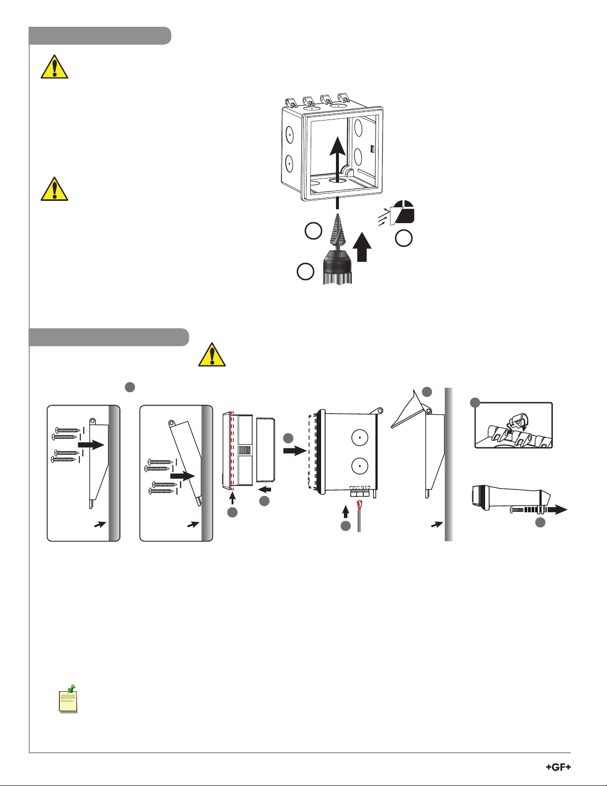
Drilling Procedure
Required Equipment (customer supplied):
1. NEMA TYPE 4X/IP66 rated conduit fittings
2. Power Drill
3. Step Drill Bit or Variable Diameter Drill Bit
4. Eye protection and gloves
Prior to drilling, account for:
• Enclosure orientation
• 9900 module(s)
• Current application wiring
• Other factors which may impact wiring access
Recommended:
When using the 9900
Relay Module (3-9900.393),
use ports above, below or across
from Relay Module terminals to
ensure wiring clearance.
Use eye protection and gloves when drilling.
Drill Enclosure conduit ports at a workbench,
not when installed on a pipe, wall or panel.
4
2
3
NOTE: Multiple conduit ports
may be required.
Do not route the sensor,
DC power, or 4 to 20 mA cables
in conduit containing AC power
wiring. Electrical noise may
interfere with sensor signal.
Wall Mount Installation
4
OR Angle mount
Wall
Flush mount
Wall 811
10
Wall
9
7
5
6
x2
1. Determine the Enclosure Orientation (hinge on top,
bottom, left or right side) and mark the desired conduit ports.
2. On a workbench, while wearing PPE, drill out the marked
conduit ports. See Drilling Procedure for details.
3. Install conduit fittings into drilled out conduit ports.
4. Determine the wall mounting position of the Hinged Cover
and drill pilot holes. Install wall anchors if required.
Mount cover using (4) #8 x 1¼ in. screws.
5. Remove 9900 gasket before installation into Rear
Enclosure!
6. If Relay Module (3-9900.393) is not used, install Module
Plug into Relay Slot and secure using two screws.
7. While gripping the 9900 face, install the Enclosure onto the
rear of the 9900, (there will be a series of clicks).
8. Install application wiring through conduit fittings.
Recommended: Do not route the sensor, DC power, or
4 to 20 mA cables in conduit containing AC power wiring.
Electrical noise may interfere with sensor signal.
9. Slide Enclosure barrels onto Hinged Cover pins.
10. Install Hinge Clip to lock the cover to the enclosure.
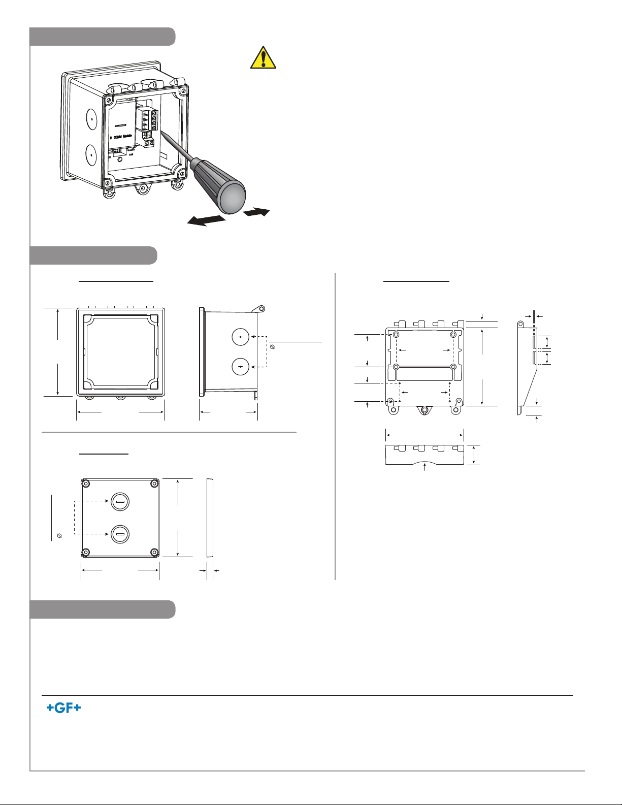
11. Secure cover with (2) #6-32 x ½ in. screws. Tighten screws
until tabs touch, do not over tighten.
Required drill sizes
Hinged Cover = 0.45 mm (11/64 in.)
Pilot holes: Dry-wall or plaster = 6.40 mm (¼ in.)
Steel panel or wood = 3.50 mm (#29: 0.136 in.)
Hinged Cover (3-9900.399-1) ONLY
Apply sufficient pressure when installing
the 9900 into the enclosure.
Make sure there are no gaps between the
9900 and the front gasket of the enclosure.
Not applying sufficient pressure can result
in leaks.
2Signet 9900 Rear Enclosure
Panel Mount Installation
Panel
6
8
7
5
4
1. Determine the Enclosure Orientation and mark the
desired conduit ports.
2. On a workbench, while wearing PPE, drill out the marked
conduit ports. See Drilling Procedure for details.
3. Install conduit fittings into drilled out conduit ports.
4. 9900 gasket required for panel installation.
5. Insert 9900 into panel cut-out. Temporarily secure the
9900 to the panel with tape or grip the 9900 face until the
Enclosure is installed.
6. Install the Enclosure onto the rear of the 9900,
compressing the gasket against the panel (there will be
a series of clicks).
7. Install application wiring through conduit fittings.
Recommended: Do not route the sensor, DC power, or
4 to 20 mA cables in conduit containing AC power wiring.
Electrical noise may interfere with sensor signal.
8. Secure Flat Cover with (4) #6-32 x ½ in. screws.
Flat Cover (3-9900.399-2) ONLY
Pipe Mount Installation
8
12
Pi
p
11
10
9
6
7
4
5
x2
Minimum pipe size:
OD: DN32 (1.25 in.)
1. Determine the Enclosure Orientation (hinge on top,
bottom, left or right side) and mark the desired conduit ports.
2. On a workbench, while wearing PPE, drill out the marked
conduit ports. See Drilling Procedure for details.
3. Install conduit fittings into drilled out conduit ports.
4. Remove 9900 gasket before installation into Rear Enclosure!
5. If Relay Module (3-9900.393) is not used, install Module
Plug into Relay slot and secure using two screws.
6. While gripping the 9900 face, install the Enclosure onto the
rear of the 9900 (there will be a series of clicks).
7. Install application wiring through conduit fittings.
Recommended: Do not route the sensor, DC power, or
4 to 20 mA cables in conduit containing AC power wiring.
Electrical noise may interfere with sensor signal.
8. Slide Hinged Cover pins into Enclosure barrels.
9. Install Hinge Clip to lock the cover to the enclosure.
10. Secure cover with (2) #6-32 x ½ in. screws. Tighten
screws until tabs touch, do not over tighten.
11. Install plastic tie-wraps or metal hose clamps through
slots in Hinged Cover. Customer supplied: ½ in. max.
width, material and length based on application.
12. Secure Enclosure to pipe, do not overstress slots.
Recommended: Use metal hose clamps for pipe
diameters DN32 (1.25 in.) to DN50 (2.00 in.).
Do not over tighten, 11.5 kg-cm (10 in-lb) max.
Hinged Cover (3-9900.399-1) ONLY
Apply sufficient pressure when installing the 9900 into
the enclosure.
Make sure there are no gaps between the 9900 and the
front gasket of the enclosure. Not applying sufficient
pressure can result in leaks.
3
Signet 9900 Rear Enclosure
Georg Fischer Signet LLC, 3401 Aero Jet Avenue, El Monte, CA 91731-2882 U.S.A. • Tel. (626) 571-2770 • Fax (626) 573-2057
For Worldwide Sales and Service, visit our website: www.gfsignet.com • Or call (in the U.S.): (800) 854-4090
For the most up-to-date information, please refer to our website at www.gfsignet.com
3-9900-399.090 Rev. 2 06/19 English © Georg Fischer Signet LLC 2019
Ordering Information
Part Number Code Description
3-9900.399-1 159 001 834 9900 Rear Enclosure Kit, Hinged Cover
3-9900.399-2 159 001 835 9900 Rear Enclosure Kit, Flat Cover
Dimensions
Enclosure Removal
For Panel Mount Installations:
Temporarily secure the 9900 with tape to the panel or grip 9900 face.
Do Not release the 9900 until removed from Enclosure.
For Wall and Pipe Mount Installations:
Remove Enclosure from Hinged Cover.
Grip 9900 face. Do Not release 9900 until removed from Enclosure.
1. Insert Flathead screwdriver between the 9900 and Enclosure
on either the right or left side of the Enclosure hinges.
2. Gently move the screwdriver back and forth, while steadily
applying forward pressure.
3. Alternate placement of the screwdriver to incrementally
release the 9900 from the Enclosure.
Remove all wiring from the 9900 before removing Enclosure.
Hinged Cover (3-9900.399-1)
Side ViewBack View
Top View
R 31.75 mm (R 1.25 in.)
8.38 mm
(0.33 in.)
10.67 mm
(0.42 in.)
2.29 mm
(0.09 in.)
24.35 mm
(0.96 in.)
(2) 12.7 mm
(0.5 in.)
97.5 mm (3.84 in.)
97.5 mm
(3.84 in.)
71.12 mm
(2.80 in.)
63.23 mm
(2.45 in.)
40.13 mm
(1.58 in.)
22.9 mm
(0.9 in.)
Rear Enclosure
Front View Side View
110 mm
(4.33 in.)
110 mm
(4.33 in.)
71.4 mm
(2.81 in.)
21.08 mm
(0.83 in.)
(8) Conduit ports
Flat Cover (3-9900.399-2)
Side ViewBack View
97.5 mm
(3.84 in.)
97.5 mm
(3.84 in.)
7.87 mm
(0.31 in.)
21.08 mm
(0.83 in.)
(2) Knock-outs

This manual suits for next models

1

Popular Enclosure manuals by other brands

Adaptec ACS 200 user guide

Adaptec

Adaptec ACS 200 user guide

SFF time P-ATX V3 manual

SFF time

SFF time P-ATX V3 manual

Kramer UTBUS-1XL user manual

Kramer

Kramer UTBUS-1XL user manual

Linkskey LKA-EDU2A user guide

Linkskey

Linkskey LKA-EDU2A user guide

Supermicro SC846 JBOD Series user manual

Supermicro

Supermicro SC846 JBOD Series user manual

XPOtool 60921 user manual

XPOtool

XPOtool 60921 user manual

FS FS-S038-2IO-24F quick start guide

FS

FS FS-S038-2IO-24F quick start guide

Labconco 3940200 user manual

Labconco

Labconco 3940200 user manual

Fantec DB-ALU2 user manual

Fantec

Fantec DB-ALU2 user manual

StarTech.com S3510BMU33B manual

StarTech.com

StarTech.com S3510BMU33B manual

Dell PowerVault MD3000 Information update

Dell

Dell PowerVault MD3000 Information update

Kicker L7T owner's manual

Kicker

Kicker L7T owner's manual

Dynacord D 12A Architects and engineers specifications

Dynacord

Dynacord D 12A Architects and engineers specifications

Supermicro SC417BE1C-R1K23JBOD user manual

Supermicro

Supermicro SC417BE1C-R1K23JBOD user manual

Fender 210 operating manual

Fender

Fender 210 operating manual

StarTech.com SM21BMU31C3 user manual

StarTech.com

StarTech.com SM21BMU31C3 user manual

EnerSys Alpha TE33-1820 Technical Advisory Bulletin

EnerSys

EnerSys Alpha TE33-1820 Technical Advisory Bulletin

Netstor NA341TB3 user manual

Netstor

Netstor NA341TB3 user manual

manuals.online logo
manuals.online logoBrands
  • About & Mission
  • Contact us
  • Privacy Policy
  • Terms and Conditions

Copyright 2025 Manuals.Online. All Rights Reserved.