GEORGE TOOLS GT9500009 Service manual

Please read and save these instructions.
Read through this owner’s manual carefully before using product. Protect yourself and others by
observing all safety information, warnings, and cautions. Failure to comply with instructions could
result in personal injury and/or damage to product or property. Please retain instructions for future
reference.
V1701
George Tools 75 Liter Mobile Parts
Washer
OPERATING INSTRUCTIONS
AND PARTS MANUAL
MODEL: GT9500009

SPECIFICATIONS
SAFETY PRECAUTIONS
2
READ ALL INSTRUCTIONS BEFORE OPERATING
SAVE THESE INSTRUCTIONS
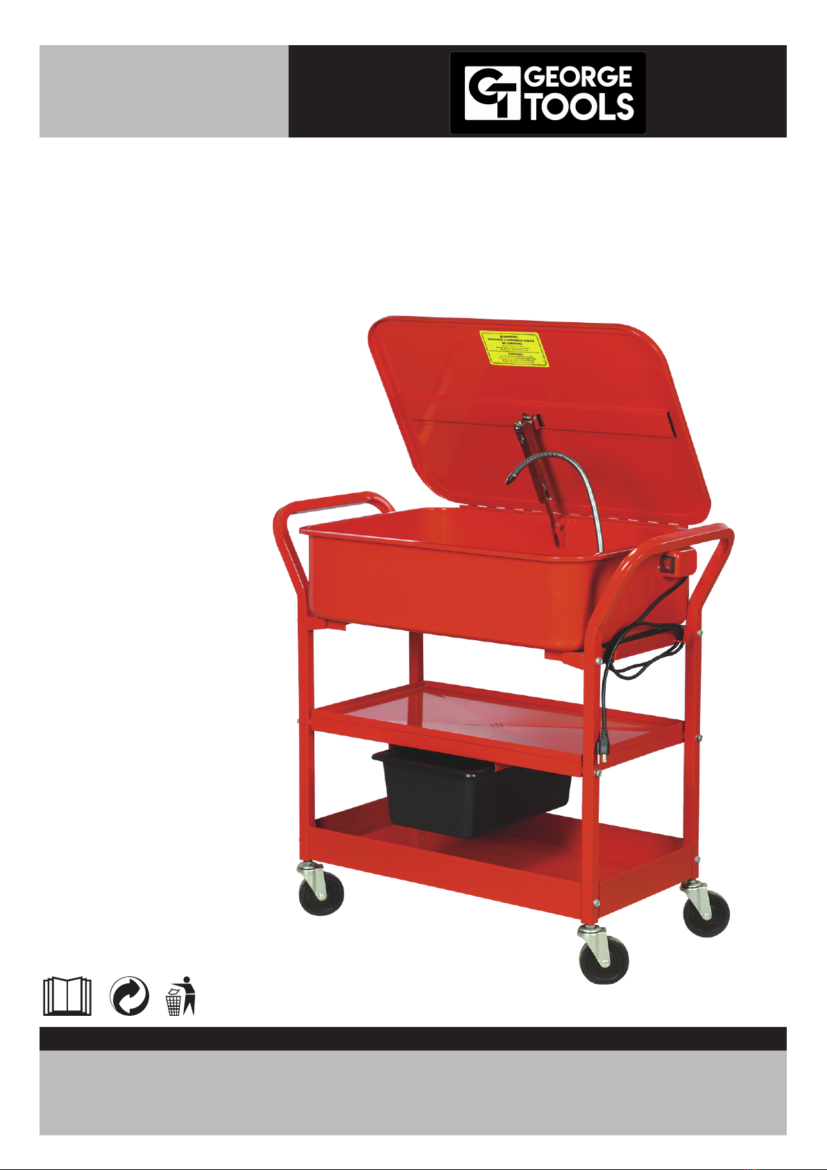
Thank you for purchasing
Mobile Parts Washer Before attempting to operate your new Parts Washer please read these instruc-
tions thoroughly. You will need these instructions for the safety warnings, precautions, assembly, oper-
ation, maintenance procedures, parts list and diagrams. Keep your invoice with these instructions.
Keep the instructions and invoice in a safe, dry place for future reference.
WARNING: The warnings, cautions and instructions discussed in this instruction manual cannot cover
all possible conditions or situations that could occur It must be understood by the operator that
common sense and caution are factors which cannot be built into this product, but must be supplied
by the operator.
1.Know your tool. Read this manual carefully. Learn the tool’s applications and limitations, as well as
specific potential hazards peculiar to it.
2.Ground all tools. If the tool is equipped with three-pin plug, it should be plugged into a three- pin elec-
trical socket. Never remove the ground pin.
3.Do not abuse cord. Never use the cord to carry tools or pull the plug from an outlet. Keep cord away
from heat, sharp edges or moving parts. Replace damaged cords immediately. Damaged cords
increase the risk of electric shock.
4.Keep work area clean and well lit. Cluttered or dark work areas invite accidents.
5.Keep children away. All children should be kept away from the work area. Never let a child handle a
tool without strict adult supervision.
6.Do not operate this tool if under the influence of alcohol or drugs. Read warning labels on prescrip-
tions to determine if your judgment or reflexes are impaired while taking drugs. If there is any doubt,
do not attempt to operate.
7.Use safety equipment. Eye protection should be worn at all times when operating this tool. Use ANSI
approved safety glasses. Everyday eyeglasses only have impact resistant lenses. They are NOT
safety glasses. Dust mask, non�skid safety shoes, hard hat, or hearing protection should be used in
appropriate conditions.
8.Wear proper apparel. Loose clothing, gloves, neckties, rings, bracelets, or other jewelry may present
a potential hazard when operating this tool. Please keep all apparel clear of the tool.
9.Don’t overreach. Keep proper footing and balance at all times when operating this product.
10.Always disconnect the tool from the power source before making any adjustments, storing, servic-
ing, or changing accessories. Such preventative safety measures reduce the risk of starting the tool
accidentally.
11.Do not use the tool if the switch does not turn it on and off Any tool that cannot be controlled with
the switch is dangerous and must be repaired.
12.Check for damage. Check your tool regularly, if part of the tool is damaged it should be carefully
inspected to make sure that it can perform its’ intended function correctly. If in doubt, the part should
SPECIFICATIONS
Tank Size
Assembled Dims
Electrical Requirements
28" x 19" x 8.2"
38" x 21.5" x 37"
110V/60HZ (230V/50HZ)
Pump Capacity
Weight
317 Gallons/hr
32.5kgs(71.5lbs.)

SAFETY PRECAUTIONS
3
be repaired. Refer all servicing to a qualified technician. Consult your dealer for advice.
13.Keep away from flammables. Do not attempt to operate this tool near flammable materials or com-
bustibles. Failure to comply may cause serious injury or death.
14.Store idle tools out of the reach of children and untrained persons. Tools may be dangerous in the
hands of untrained users.
POWER REQUIREMENTS
This product is designed to operate on a properly grounded voltage , single-phase alternating current
(ac) power source fused with a 20 amp time delayed fuse or circuit breaker It is recommended that a
qualified electrician verify the ACTUAL VOLTAGE at the receptacle into which the product will be
plugged and confirm that the receptacle is properly fused and grounded.
DO NOT OPERATE THIS PRODUCT if the ACTUAL power source voltage is more or less 10% than
the correct voltage. Contact a qualified electrician if this problem exists. Improper performance and/or
damage to the product will result if operated on inadequate or excessive power
Consult a qualified electrician for proper installation of receptacle at the power source.
This product must be grounded while in use to protect the operator from electrical shock. If you are not
sure if your outlet is properly grounded, have it checked by a qualified electrician. Do not cut off the
grounding prong or alter the plug in any way and do not use any adapters between the product’s power
cord and the power source receptacle. Make sure the POWER switch is OFF then connect the power
cord to a properly grounded voltage single phase, 20 amp power source.
EXTENSION CORDS
For optimum performance, an extension cord should not be used unless absolutely necessary. If nec-
essary, care must be taken in selecting an extension cord appropriate for use with your specific prod-
uct.
Select a properly grounded extension cord that will mate directly with the power source receptacle and
the power cord without the use of adapters. Make certain that the extension is properly wired and in
good electrical condition.
Extension cords must be a #12 gauge cord at the smallest. Do not use an extension cord over 25 ft. in
length.
CONNECT TO POWER SOURCE
POWER SOURCE CONNECTION
WARNING HIGH VOLTAGE DANGER FROM POWER SOURCE!

1.Locate the two Handles (04) and the Lower Shelf (13).
2.Align the holes in the bottom of the Handles with the 4 holes in the corners of the Lower Shelf.
3.Place Flat Washer (03) onto Bolt (02) and insert Bolt through Handle and Lower Shelf.
4.Place Flat Washer (03) and Lock Nut (07) onto end of Bolt and hand tighten.
5.Repeat steps 3-4 for remaining holes in Lower Shelf.
Note: Do not fully tighten nuts at this time.
1.Locate the Middle Shelf (12) and the Tank Drain (14).
2.Insert the Tank Drain into the slots located in the bottom of Middle Shelf
3.Align the holes in the 4 corners of the Middle Shelf with the holes in the middle of the Handles.
4.Place Flat Washer onto Bolt and insert Bolt through Handle and Middle Shelf.
5.Place Flat Washer and Lock Nut onto end of Bolt and hand tighten.
6.Repeat steps 4-5 for remaining holes in Middle Shelf
Note: Do not fully tighten nuts at this time.
1.Locate the Left Tank Mount (06) and Right Tank Mount (25).
Note: Right Tank Mount has hooks for electrical cord storage.
2.Align the holes in the Left Tank Mount with the uppermost holes in either Handle.
3.Place Flat Washer onto Bolt and insert Bolt through Handle and Left Tank Mount.
4.Place Flat Washer and Lock Nut onto end of Bolt and hand tighten.
5.Repeat steps 3-4 for remaining hole in Left Tank Mount.
6.Align the holes in the Right Tank Mount with the holes in the remaining Handle. Hooks on Right Tank
Mount should be facing AWAY from center on unit.
7.Follow steps 3-5 to install Right Tank Mount. Note: Do not fully tighten nuts at this time.
Note: You may need a second person to help properly align the Tank to the Tank Mounts.
1.Place Flat Washer onto Short Bolt (11) and insert through hole in Tank Mount.
2.Place Adjusting Washer onto Short Bolt.
3.Slide the end of the Short Bolt through the hole in the mounting bracket on Tank (08) bottom.
4.Place Flat Washer and Lock Nut onto end of Short Bolt and hand tighten.
5.Repeat steps 1-4 for remaining seven holes in Tank Mounts.
Note: The Power Switch is on the RIGHT side of the Tank and should be positioned above the RIGHT
Tank Mount.
1 At this time, fully tighten all of the Lock Nuts onto the bolts which were installed in the previous sec-
tion.
1.Align the slots on the rear of the Pump Housing (31) with the tabs on the inner right side of the Tank.
2.Carefully slide the Pump Housing slots onto the tabs of the Tank.
4
Lower Shelf
Middle (Parts Drying) Shelf
Tank Mounts
Tank
Mounting the Pump
Tightening the Hardware
ASSEMBLY

3.Lower Pump Housing until it is resting on the Tank bottom.
1.Position the Washboard (05) so that the lipped edges are facing down and the rectangular cut�out
is on the right side.
2.Place your index fingers through the holes located at the front left and right rear of the Washboard.
3.Align the lipped edges of Washboard with the mounting brackets on inner Tank walls and gently
lower into place.
1.Locate the four Castors (01) and the four Spring Washers (39).
2.Place a Spring Washer onto the threaded end of Castor
3.Insert Castor threads into hole on bottom of Handle.
4.Tighten Castor in place with wrench.
5.Repeat steps 2-4 for remaining Castors.
Note: Two Castors have locks these should be installed side by side, to allow you to control movement
of the Parts Washer
1. Sit it on firm, flat, level surface in a well ventilated area and away from any open flames.
2. Fill only with a non-flammable water-based degreaser or cleaning agent, such as Simple Green to
just below the level of the parts shelf (approximately 12 gallons).
3.Follow the degreaser manufacturer’s instructions carefully.
4.Do not fill with flammable solvents such as kerosene, gasoline, etc.
Always wear protective clothing, gloves and goggles when using your Parts Washer
1.Open the Parts Washer Lid (09) and place parts to be washed on the washboard.
2.Position the Flexible Nozzle (26) so that it is directly above your parts.
3.Turn the Power Switch (20) to the ON position.
4.Clean parts as needed.
5.Turn Power Switch to the OFF position.
6.Place parts on Drying Shelf until completely dry.
7.Empty Drain Tank, as needed, by sliding out of Drying Shelf brackets.
The pump of your parts washer may be damaged if you use solvents other than those listed.
ASSEMBLY
OPERATION
5
Castors
INSTALLING YOUR PARTS WASHER
Washboard
WARNING
WARNING
Clean off any accidental splashes of
degreaser on skin immediately, following the
degreaser manufacturer’s instructions
carefully. Seek medical attention if necessary.

WHEN NOT IN USE
1Switch off pump, close the lid and disconnect from the electrical supply.
2. Disconnect from the electrical supply before carrying out any maintenance or cleaning on the parts
washer
MAINTENANCE
1.The lid incorporates a fusible link to close the lid in the event of a fire. This link is non-resetting and
must be replaced once it has been triggered.
2.Clean the pump filter regularly by sliding it away from the pump housing and rinsing in clean
degreaser
3.Do not allow the level of liquid in the parts washer to fall below the pump inlet, as damage to the
pump can result.
4.Change degreaser as needed. Tank can be drained by removing the Drain Plug (38) located on
bottom of Tank.
6
OPERATION
Fusible link
One piece tank
(working capacity
approx. 12 gal.)
Storage shelf
(flat side down)
Lid(keep closed
when not in use)
Flexible spray
pipe and nozzle
Filter
ON/OFF
Switch
Drain plug
Drying shelf
Drain tank

7
PARTS LIST AND DIAGRAM
Part
No. Description Qty.
THIS PARTS LIST AND LINE DRAWING ARE FOR REFERENCE ONLY.
THIS TOOL CAN ONLY BE SERVICED AT AN AUTHORIZED REPAIR FACILITY
Castor
Bolt
Flat Washer
Handle
Wash board
Left Tank Mount
Lock Nut
Tank
Tank Lid
Fusible
Short Bolt
Middle
Lower
Drain Tank
1
2
3
4
5
6
7
8
9
10
11
12
13
14
4
12
32
2
1
1
16
1
1
1
8
1
1
1
Part
No. Description Qty.
Power Cord
Cable Clamp
Switch Box
Screw
Flat Washer M4
Power Switch
Cable Guard
Hex Nut M4
Spring Washer
Wire Flange
Right Tank Mount
Flexible Nozzle
Pump Housing Cover
Filter Cover
15
16
17
18
19
20
21
22
23
24
25
26
27
28
1
1
1
7
7
1
2
5
5
1
1
1
1
1
Part
No. Description Qty.
Filter Screen
Pump Assembly
Pump Housing
Gromme
Spigot
Grommet
Hex Nut M5
Flat Washer
Screw M5x20
Drain Plug
Spring Washer
Adjusting Washer
29
30
31
32
33
34
35
36
37
38
39
40
1
1
1
1
1
1
1
1
1
1
4
8
Table of contents
Other GEORGE TOOLS Washer manuals
Popular Washer manuals by other brands

Sharp
Sharp ES-HFH714AWC-PL user manual

Kenmore
Kenmore 796.4219#90# Service manual

Indesit
Indesit IWB 6113 Instructions for use

Whirlpool
Whirlpool AZA 9783 GG Quick reference guide

Siemens
Siemens WM11E26SBC Instructions for installation and use

Siemens
Siemens WM10W468IL Instruction manual and installation instructions