GeoSIG VE-1 Series User manual

VE-1x/2x Series Velocity Sensor
Installation and Operation Manual
Company:
GeoSIG Ltd
Wiesenstrasse 39, 8952 Schlieren, Switzerland,
Tel: +41 44 810 21 50, Fax: +41 44 810 23 50, E-mail: info@geosig.com
Author:
Ralph Böniger
Checked:
Dr. Talhan Biro
Approved:
Johannes Grob
Distribution:
GeoSIG Ltd, Customer on request

GS_VE-1x_2x_Operation_Manual_V09.docx/14.09.2020
VE-1x/2x Series Velocity Sensor Page 2 / 10
Document Revision
Version
Action
21.09.1995
First issue
21.01.1997
One document for all the GSV types
29.10.2001
Update technical issues
13.05.2003
Change model number to GSV types
24.09.2003
Update technical issues
17.02.2005
Updated naming for 1x and 2x only, TB
12.06.2014
New Logo and updated address
05.05.2015
Correction of description
14.09.2020
Update technical specification
Disclaimer
GeoSIG Ltd reserves the right to change the information contained in this document without notice. While the information
contained herein is assumed to be accurate, GeoSIG Ltd assumes no responsibility for any errors or omissions.
Copyright Notice
No part of this document may be reproduced without the prior written consent of GeoSIG Ltd. The software described in
this document is furnished under license and may only be used or copied in accordance with the terms of such a license.
Trademark
All brand and product names mentioned are trademarks or registered trademarks of their respective holders.
All rights reserved
GeoSIG Ltd
Switzerland

GS_VE-1x_2x_Operation_Manual_V09.docx/14.09.2020
VE-1x/2x Series Velocity Sensor Page 3 / 10
Table of Contents
1. INTRODUCTION ............................................................................................................................... 4
2. INSTALLATION ................................................................................................................................ 4
2.1. INSTALLING ..................................................................................................................................... 4
2.1.1. Verifying Installation ................................................................................................................ 5
2.2. ELECTRICAL CONNECTION ................................................................................................................ 5
2.2.1. Connector Pin Assignment ...................................................................................................... 5
2.2.2. Connecting to a Recorder ........................................................................................................ 7
2.2.3. Cable Configuration, Specification and Length ......................................................................... 7
3. OPERATION AND CONFIGURATION .............................................................................................. 8
3.1. AXIS ORIENTATION CONFIGURATION .................................................................................................. 8
3.2. SCALE FACTOR / GAIN...................................................................................................................... 8
3.3. SELF TEST ...................................................................................................................................... 8
3.4. OPERATION CONFIRMATION .............................................................................................................. 9
4. SPECIFICATIONS............................................................................................................................. 9
5. MAINTENANCE ................................................................................................................................ 9
6. THEORY OF OPERATION ................................................................................................................ 9

GS_VE-1x_2x_Operation_Manual_V09.docx/14.09.2020
VE-1x/2x Series Velocity Sensor Page 4 / 10
1. Introduction
The GeoSIG VE-1x/2x series velocity sensors consist of the following sensor types:
Frequency response 1 Hz to 315 Hz:
• VE-11 uniaxial
• VE-12 biaxial
• VE-13 triaxial
Frequency response 4.5 Hz to 315 Hz:
• VE-21 uniaxial
• VE-22 biaxial
• VE-23 triaxial
All sensor types are implemented in the same waterproof, 94 x 96 x 193 mm cast aluminium housing. The
modules inside the VE velocity sensors are 1 to 3 high quality geophones, geophone signal amplifier, gain
ranger, geophone integrator (VE-1x only) and current loop interface for 0 to 20 mA output. Since the modules
can easily be added regarding specific user requirements, the VE velocity sensors offer maximum versatility
in obtaining the desired performance.
Small size and single bolt fixation allows for both saving space and installation time. Levelling is accomplished
via three-point levelling screws. Alternatively, the flanges that support levelling can be used for mounting if
desired.
2. Installation
The VE velocity sensors are fairly simple devices to use, but some care must be taken in installation to be
assured of proper performance. Because there are many considerations, we recommend that before starting
installation, you review each section of this manual to ensure the best possible chance of a simple installation
that works right the first time. Prior to and after installation we recommend that you verify functionality of the
VE velocity sensor and the cable assembly with testing the output signal and test pulse response of the sensor.
This may save time and trouble as well as give confidence that connections are done correctly.
The location of the sensor, preferably as close as possible to the associated recorder, should be as level and
smooth as possible and the foundation should be of concrete, rock or similar material which is perfectly bonded
to the ground or structure to be measured or monitored. Special installations such as installing vertically on a
reinforced concrete wall (i.e. vertical foundation) are also possible, provided that the sensor is compatible with
the required orientation, the location is appropriately selected and the sensor is properly mounted.
2.1. Installing
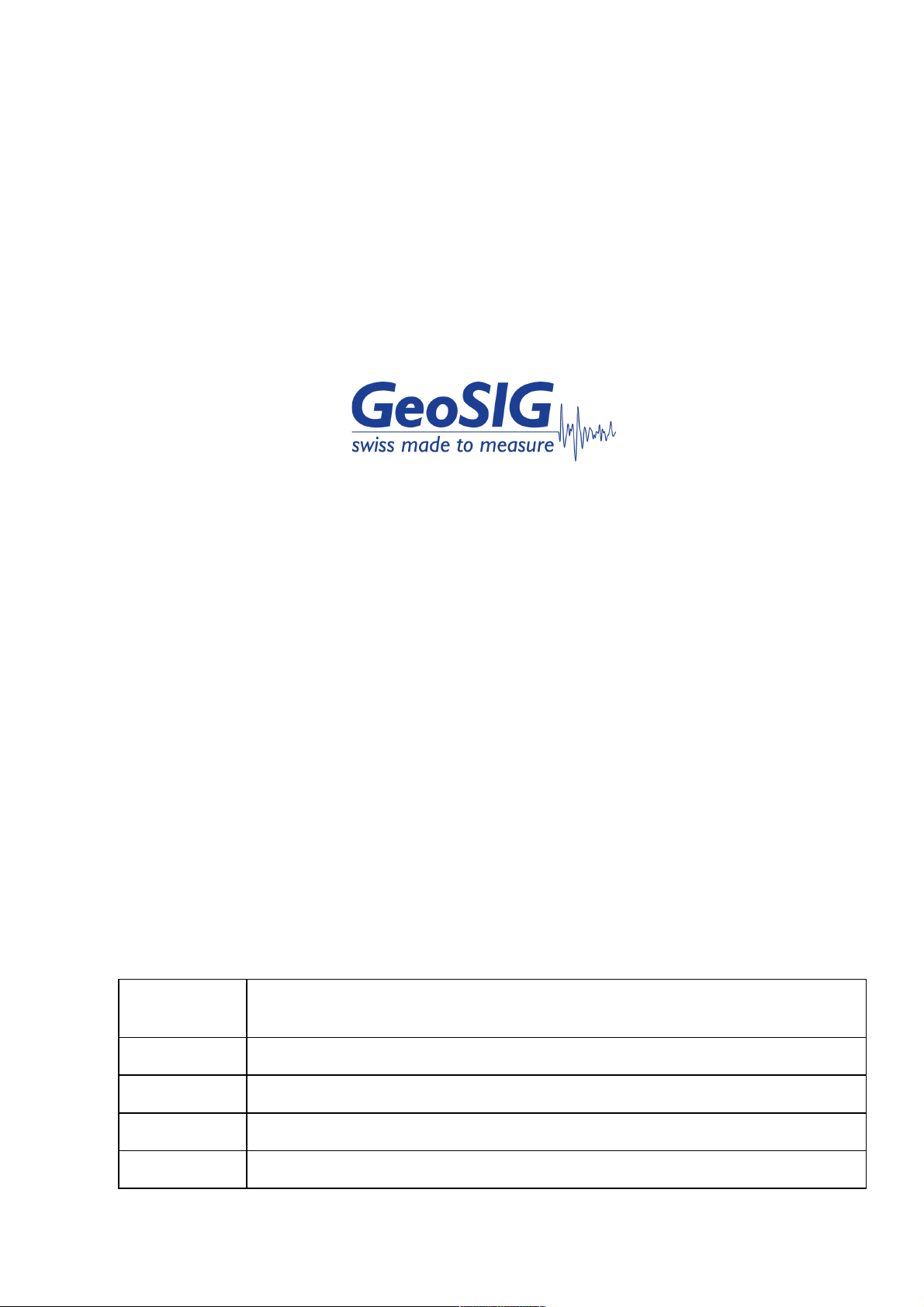
The VE velocity sensor must be firmly mounted to the foundation and levelled using the single centre pivot bolt
and the three-point levelling screws as shown in Figure 1. The "T" slot on the bottom of the sensor housing is
made to accept an M8 x 35 mm stainless steel bolt head. This centre pivot bolt is first fastened to the foundation
leaving approximately 18 – 20 mm of height above the installation surface. The sensor, at its “T” slot, is then
slipped onto the bolt head and oriented in the proper direction. The three-point levelling screws are then
adjusted and tightened to both level the sensor and securely fasten it to the surface.
In order to prevent any damage to the sensor housing or the fixation screw and/or anchor, do not
tighten the levelling screws using excessive force.
Use a bubble level and place it on the top of sensor surface, level first along one axis, then the other as final
levelling adjustments are made.

GS_VE-1x_2x_Operation_Manual_V09.docx/14.09.2020
VE-1x/2x Series Velocity Sensor Page 5 / 10
Figure 1. Mounting the VE Velocity Sensor
2.1.1. Verifying Installation
Check to be sure that the sensor is aligned to produce the desired output signals as follows:
• For any axis or any combination of axes, a movement in the axis (or combination) direction indicated on
the label of the sensor housing should produce a positive output signal, which can be observed on the
output of the sensor (via the associated recorder).
Note that the standard orientations of the axes are in accordance with the right-hand rule:
• positive x-axis is in the direction of the thumb,
• positive y-axis is in the direction of the pointer finger
• positive z-axis in the direction of the middle finger of the right hand.
Make sure that your sensor is oriented properly for your requirements.
Please contact GeoSIG if you wish to change any axis direction / orientation.
You might as well utilize your sensor by not fixing it to the foundation (in the case of horizontal
foundations) but rather by placing it on the foundation, taking measurements and relocating for temporary
or mobile measurements. However, the velocity sensors must be fixed to the ground as soon as the
vibrations measured are higher than 1/3 of gravitational acceleration (> 3.27 g).
2.2. Electrical Connection
2.2.1. Connector Pin Assignment
The VE velocity sensors may be equipped with different connection versions:
• with 2 m cable and no connector
• with 2 m cable and a 12 pin male connector
• with a 12 pin male housing plug
• (open frame) with direct PCB connection
The connections and pin assignment are shown in Table 1 through Table 3. All connectors use the same 12
pin connector. Following connectors are used in the VE velocity sensors:
• Sensor housing plug, 12-pin male
• Sensor cable connector (to connect VE to GSR), 12-pin male
• Extension cable connector (to connect to VE cable connector), 12-pin female
Fixing
Screw
Levelling
Screw
Anchor
Levelling
Screw

GS_VE-1x_2x_Operation_Manual_V09.docx/14.09.2020
VE-1x/2x Series Velocity Sensor Page 6 / 10
Table 1. VE Internal PCB Pin Assignment
12 Pin
Name
12 Lead Cable Colour
Description
1
Sens_X_HI
white
X-Signal high
2
Sens_X_LO
brown
X-Signal low
3
Sens_Y_HI
green
Y-Signal high
4
Sens_Y_LO
yellow
Y-Signal low
5
Sens_Z_HI
grey
Z-Signal high
6
Sens_Z_LO
pink
Z-Signal low
7
S_Test
blue
Sensor Test Signal
8
AGND
red
Analog Ground
9
V_EXT
black
External Voltage (12VDC)
10
AGND
violet
Analog Ground
11
S_MODE
grey-pink
Sensor Mode Signal
12
AGND
red-blue
Analog Ground
Table 2. VE Sensor Housing Pin Assignment
12 Pin
Name
12 Lead Cable Colour
Description
1
Sens_X_HI
white
X-Signal high
2
Sens_X_LO
brown
X-Signal low
3
Sens_Y_HI
green
Y-Signal high
4
Sens_Y_LO
yellow
Y-Signal low
5
Sens_Z_HI
grey
Z-Signal high
6
Sens_Z_LO
pink
Z-Signal low
7
S_Test
blue
Sensor Test Signal
8
AGND
red
Analog Ground
9
V_EXT
black
External Voltage (12VDC)
10
AGND
violet
Analog Ground
11
S_MODE
grey-pink
Sensor Mode Signal
12
AGND
red-blue
Analog Ground
Table 3. VE Sensor Cable Pin Assignment
12 Pin
Name
12 Lead Cable Colour
Description
1
Sens_X_HI
white
X-Signal high
2
Sens_X_LO
brown
X-Signal low
3
Sens_Y_HI
green
Y-Signal high
4
Sens_Y_LO
yellow
Y-Signal low
5
Sens_Z_HI
grey
Z-Signal high
6
Sens_Z_LO
pink
Z-Signal low
7
S_Test
blue
Sensor Test Signal
8
AGND
red
Analog Ground
9
V_EXT
black
External Voltage (12VDC)
10
AGND
violet
Analog Ground
11
S_MODE
grey-pink
Sensor Mode Signal
12
AGND
red-blue
Analog Ground
The VE velocity sensor operates from a single unregulated supply voltage of 12 VDC (10 to 15 VDC). The
analog output voltages are referenced to 2.5 VDC. Analog Reference Voltage available internally on the PCB
represents the analog common.
Never connect the 2.5 VDC to power common (GND)

GS_VE-1x_2x_Operation_Manual_V09.docx/14.09.2020
VE-1x/2x Series Velocity Sensor Page 7 / 10
2.2.2. Connecting to a Recorder
The following points must be considered when connecting the VE sensor to a recording system:
• In case of a voltage output the output range is 2.5 VDC to ± 2.5 V (i.e. 0 to 5 V range for peak to peak)
• In case of a current output the output range is 10 mA to ± 10 mA (i.e. 0 to 20 mA range for peak to
peak).
2.2.3. Cable Configuration, Specification and Length
The cable configuration, specification, length and quality of installation affect the quality of analog signal
received, the cost of materials and the long-term reliability of the system. When cabling is ordered as part of
the system, GeoSIG engineers review the installation plan and the cable specifications as well as
environmental conditions to assist you in achieving a reliable and cost effective installation. Following the
guidelines outlined below will help further ensure your success.
A cable must not only be able to transmit power and signals, but must also survive the environment in which
it is placed. This includes chemical exposure, UV exposure, impact and cut protection, temperature extremes
and any regulatory safety requirements. Because the permutations are so numerous, it is not practical to
specify particular manufacturer's cable part numbers here. However, GeoSIG engineers will work with you to
help you specify an appropriate cable. The electrical parameters required for transmission of signals and power
is discussed below.
The cable construction must be an overall shielded twisted pair type for optimal protection from
electromagnetic interference (EMI) sources along the path of transmission. Normally the shield can be a foil
wrapper with a drain wire. However, if the cable is to be installed in close proximity to high voltage power
cables an overall braided shield is additionally recommended.
For optimum noise shield performance and maximum cable run lengths, the VE velocity sensor signals should
be paired as shown on Table 4.
Table 4. Cable Wire Pair Assignments
Pair
Wire Pair Function
1
X-Signal high and low
2
Y-Signal high and low
3
Z-Signal high and low
4
S_Test and AGND
5
V_EXT and AGND
6
S_MODE and AGND
Connect the cable shield to the local ground at the recorder
Cables do not generate noise. However, longer cables increase the amount of the contributed noise from
external sources. Cables should always be routed as far from power distribution and control wiring as possible.
Again, if the cable needs to be installed close to power cables, an overall braided shield is additionally
recommended.
Cable resistance primarily determines the maximum cable length. This is not an issue related to analog signal
degradation since both the signal currents and the transmission bandwidth are comparatively quite low. The
main limitation is an outcome of voltage drop in the power supply due to cable resistance. The following table
lists typical conductor resistance values for twisted pair shielded cables.

GS_VE-1x_2x_Operation_Manual_V09.docx/14.09.2020
VE-1x/2x Series Velocity Sensor Page 8 / 10
Table 5. Typical Twisted Pair Shielded Cable Specifications
Diameter mm
Square mm2
Resistance
W
/km
AWG
0.25
0.051
371
30
0.42
0.14
135
-
0.45
0.159
114
25
0.51
0.204
93
24
0.53
0.22
86
-
0.64
0.321
52
22
0.80
0.5
39
-
0.81
0.515
34
20
0.98
0.75
26
-
1.02
0.817
21
18
1.13
1.0
19
-
While selecting a cable, a maximum total resistance of 100 W should be taken into account and the values out
of the table above must be doubled (forward and back path) to have the correct resistance value.
Cable length may be extended or a thinner cable might be used via utilizing several conductors for the VA+
and GND signal. Geophones using current loop output will draw 75 mA, maximum.
Verify that voltage drop does not lower the voltage at the geophone to less than 10 VDC.
3. Operation and Configuration
3.1. Axis Orientation Configuration
The axis orientation configuration is printed on each sensor’s label that takes place on the housing. Geophones
are sensitive to the gravity; therefore the VE velocity sensor has to be placed in accordance with the intended
(and as purchased, i.e. horizontal or vertical) orientation.
Do not exchange the geophone axis orientation(s) without contacting GeoSIG. Doing so will
void the warranty of the instrument and might as well damage it completely.
The polarity of the signal can be changed basically by exchanging the connections to the geophone.
Also this action has to be coordinated with GeoSIG and must be executed by a skilled electrician.
3.2. Scale Factor / Gain
The standard scale factor is 100 mm/s. Other ranges are available. A gain ranging option allows the user to
select one of three scale factors by connecting S_TEST and S_MODE to VA+ or GND. See the following table.
Table 6. Scale Factor / Gain / Test; 0 = Ground, 1 = VA+
S-Mode
S-Test
Gain
0
0
Mid Gain
1
0
High Gain
0
1
Mid Gain with sensor test
1
1
Low Gain
3.3. Self Test
When S_MODE is grounded and S_TEST is connected to VA+, the VE velocity sensor responds with a pulse.
The pulse is positive and decays to zero after releasing the test input condition. This test is an excellent
indication about the proper working of the sensor. Geophones might get damaged due to large shocks (e.g.
by falling down to the ground). Such a damaged geophone would have developed internal contact between

GS_VE-1x_2x_Operation_Manual_V09.docx/14.09.2020
VE-1x/2x Series Velocity Sensor Page 9 / 10
the moving part and have the coil fixed. The self-test wave perfectly shows such a defect because the response
on the self-test input would be completely different than the standard.
3.4. Operation Confirmation
Confirmation of the operation is easily accomplished with a few simple measurements, which involve checking
of:
• the output voltage in normal operation,
• the power consumption,
• the wave-form of the test pulse.
4. Specifications
Please refer to the technical leaflet of your sensor.
5. Maintenance
The VE velocity sensors are sealed from the environment. As such, there is no routine or additional
maintenance required. For critical and long-term applications we recommend the periodic use of the self-test
functionality (see section 3.3. Self Test) to verify the integrity of the system and installation. In precision
applications we recommend a calibration audit interval of 1 year. GeoSIG can execute a calibration check,
which is executed by using an accelerometer with a hardware integrator as reference velocity sensor on a
shaker.
6. Theory of Operation
The VE-1x/2x contains the following electronic blocks:
è
è
è
è
1
2
3
4
5
1 Geophone
- Standard Geophone 4.5 Hz
2 Signal Conditioner
- Damping Resistor
- Amplifier
3 Gain Selection (Optional)
- 3 Gains selectable 1:10:100 (standard)
- other ranges optional
4 Geophone Integrator
- Makes the 1 Hz response (only VE-1x)
f
4.5 Hz
v
Geophone
V
I

GS_VE-1x_2x_Operation_Manual_V09.docx/14.09.2020
VE-1x/2x Series Velocity Sensor Page 10 / 10
5 Voltage to current converter (Optional-GS-320CL)
- 0 – 20 mA
Original
Characteristic
of Geophone
Additional Gain
Improves the low frequency
response between 1 - 4.5 Hz
Final Signal:
1 Hz response
to 315 Hz
+
=
v
f
f
4.5 Hz
1 Hz 4.5 Hz
v
f
v
1 Hz
This manual suits for next models
7
Table of contents
Other GeoSIG Accessories manuals