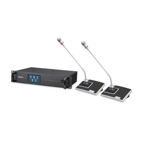
Gestton EG-7240 User manual

POWER
6V IN
USB
DIGI TAL WIR ELESS C ONFE RENCE S YSTEM
POWE R
Digital Wireless onference
EG-7240M EG-7240C EG-7240D
【INSTRUCTION MANUAL】
X
Y
Digital Wireless Conference System
EG-7240
USER MANUAL

Safety instrucons
When using this electronic device, basic precauons should always be taken,
including the following:
1 Read all instrucons before using the product.
2 Do not use this product near water (e.g., near a bathtub, washbowl, kitchen
sink, in a wet basement or near a swimming pool etc).
3 Use this device when you are sure that the controller has a stable base and it is
fixed securely.
4 This product, in combinaon with loudspeakers and amplifier may be capable
of producing sound levels that could cause permanent hearing loss. Do not
operate for a long period of me at a high volume level or at a level that is
uncomfortable. If you experience any hearing loss or ringing in the ears, you
should consult with otorhinolaryngologists.
5 The product should be located away from heat sources such as radiators, heat
vents, or other devices that produce heat.
6 The product should be connected to a power supply that is described in the
operang instrucons or are marked on the product.
7 Before the wiring always unplug equipment’s from main power supply.
8 The power supply should be undamaged and never share an outlet or extension
cord with other devices. Never leave device plugged in the outlet when it is not
being used for a long period of me.
9 Care should be taken that objects do not fall into liquids and liquids would not
be spilled on the device.
10 Do not block any venlaon openings. Install in accordance with the
manufacturer’s instrucon.
USER MANUAL | EG-7240 Digital Wireless Conference System
Safety instrucons
11 Do not defeat the safety purpose of the polarized or grounding-type plug. A
polarized plug has two blades with one wider than the other. A grounding-type
plug has two blades and a third grounding prong. The wide blade or the third
prong are provided for your safety. If the provide plug does not fit into your
outlet, consult an electrician for replacement of the obsolete outlet.
12 Protect the power cord from being walked on or pinched parcularly at plugs,
convenience receptacles, and point where they exit from the apparatus.
13 Only use aachments/accessories specified by the manufacturer.
14 Unplug this apparatus during lightning storms or when unused for long periods
of me.
15 The apparatus shall be connected to a main socket output with a protecve
earthing connecon.
16 The product should be serviced by qualified service personnel if :
- The power supply or the plug has been damaged.
- Objects have fallen into or liquid has been spilled on the product.
- The product has been exposed to rain.
- The product has been dropped or the enclosure damaged.
- The display or main board damaged
17 There are some areas with high voltage inside, to reduce the risk of electric
shock , do not remove cover of the controller or power supply. The cover
should be removed by qualified personnel only.
USER MANUAL | EG-7240 Digital Wireless Conference System
CAUTION
RISK OF ELECTRIC SHOCK
DO NOT OPEN
To reduce the risk of electric shock,do not remove screws,
No user-serviceable parts inside.Refer servicing to qualified
service personnel.To reduce the risk of fire,electric shock
or product damage,do not expose this apparatus to rain,
moisture,dripping or splashing and that no objects filled
with liquids,such as vases,shall be placed on the apparatus.

WEEE Direcve
USER MANUAL | EG-7240 Digital Wireless Conference System
If the me arises to throw away your product, please recycle all possible component.
This symbol indicates that when the end-user wishes to discard this
product, it must be sent to separate collecon facilies for recovery
and recycling. By separang this product from other household-type
waste, the volume of waste sent to incinerators or land-fills will be
reduced and natural resources will thus be conserved.
The Waste Electrical and Electronic Equipment Direcve (WEEE Direcve) aims to
minimise the impact of electrical and electronic goods on the environment.
Geson comply with the Direcve 2012/19/EU of the European Parliament on
waste electrical finance the cost of treatment and recovery of electronic
equipment (WEEE) in order to reduce the amount of WEEE that is being disposed
of in land-fill site.
All of our products are marked with the WEEE symbol; this indicates that this
product must NOT be disposed of with other waste. Instead it is the user’s
responsibility to dispose of their waste electrical and electronic equipment by
handing it over to an approved reprocessor.
Table of contents
Product overview
1.General Function ............................................................................................................. 1
.2 Installation .......................................................................................................................1
.3 Front Pannel.....................................................................................................................1
.4 Rear Panel.........................................................................................................................2
.5 Chairman Unit ..................................................................................................................3
.6 Delegate Unit ...................................................................................................................3
.Charger Unit .....................................................................................................................47
Operation
8. Menu of Main Controller ...............................................................................................4
9.Unit Menu ........................................................................................................................10
Software guide
10.Software .............................................................................................................13Guide
System specifications
11.System Connection .......................................................................................................20
12.Specification ..................................................................................................................21
1 FAQ3...................................................................................................................................22

1.This equipment shall be used within working temperature(-10℃
~45℃).
2.The minimum installation gap for the main controller shall be
20CM & there should not be any covering on the ventilated hole
to get better ventilation.
3.Please install the antenna in a certain way. Try to keep the
receiving antenna as close as possible to the launch antenna.
Caution:
USER MANUAL | EG-7240 Digital Wireless Conference System
Product overview
Controller front panel.…………………..1
Controller rear panel..…………………..1
System connecon diagram............2
General specificaon.....................3
USER MANUAL | EG-7240 Digital Wireless Conference System 02
Product overview
1.General Function
①Camera tracking can be set without any other anxiliary equipment.
② Main controller adopts 4.3 inch touch screen with friendly interface. Speaking uint adopts
1.7 inch TFT colorful screen.
③System can be connected with multiple cameras via PELCO P/D, YAAN, BRC-Z330 camera
agreement.
④Maximum 1 chairman unit & 126 delegate units can be connected to one system. More
than 2 systems can work in the same venue when using different frequency channel.
Maximum 1 chairman unit & 3 delegate units can speak at the same time.
⑤Address can be edited manually.
⑥Meet mode: FIFO, LIFO, Limited
⑦Chairman unit adopts priority function to cut off delegate unit.
⑧ With built-in Li-battery in microphone unit, can work for 7 hours constantly.
⑨Main controller can shut all units down with “One Key Shutdown” function.
2.Installation
①System must be edited address before using. Two way of “Edit address”: “Auto Setup” &
“Manual Setup”
②Connect two receiving antenna to the rear panel, then pull the antenna to about 45°angle.
③Power supply: AC110~220V.
④To get the best communication, the minimum installation height to the ground shall be
1m, the minimum distance between launch antenna & receiving antenna shall be 2m,
& the minimum distance to wall shall be 1m.
⑤Keep antennas away from interference such as computer, digital equipment, TV & also big
metal item.
⑥Try to avoid putting barrier in between launch antenna & receiving antenna.
3.Front Pannel
USB
DIG ITAL WI RELES S CONFE RENCE S YSTEM
POW ER
3
21
①USB recorder, supports max.64G thumb drive in FAT32, MP3 recording format.
②Touch screen window: To indicate & set main controller parameter.
③Power switch & indication light.
4.Rear Pannel
①Fuse holder, for 2.5A fuse;
②AC220V power socket;
③BNC port for control signal receiving antenna.;
④USB port, to connect with PC;
⑤Camera port, for both RS485 & RS232 communication. When connecting RS485 camera,
connect RX to TXD of camera, connect TX to RXD of camera, G to be grounded;
⑥RS-232 port, for video switcher;
⑦RS-232 port, programmable data port, to connect to central controller;
⑧Camera port, for RS232 camera;
⑨Audio channel UHF-C/D receiving antenna connector(BNC type);
⑩Balance audio output;
⑪6.3 audio output;
⑫Audio channel UHF-A/B receiving antenna connector(BNC type);
21 3 4 5 6 9 10 11 12
8
7
Product overview
01

03
USER MANUAL | EG-7240 Digital Wireless Conference System USER MANUAL | EG-7240 Digital Wireless Conference System 04
Product overview
5.Chairman Unit
①Mic Capsule: to pickup vocal & transfer to amplify.
②Mic Light Loop
③TFT colorful window: to indicate status & set parameter.
④ESC
⑤Enter
⑥Up
⑦Down
⑧Turn down
⑨Turn up
⑩Priority Button: to cut off all the delegate units.
⑪On/Off Button: to turn on/off the unit.
⑫Power switch: Press it for about 3 seconds to turn on/off the
power.
⑬ Charging Jack: to connect with charger.
6.Delegate Unit
①Mic Capsule: to pickup vocal & transfer to amplify.
②Mic Light Loop
③TFT colorful window: to indicate status & set parameter.
④ESC
⑤Enter
⑥Up
⑦Down
⑧Turn down
⑨Turn up
⑩On/Off Button: to turn on/off the unit.
⑪Power switch: Press it for about 3 seconds to turn on/off the
power.
⑫Charging Jack: to connect with charger.
POWER
6V IN
1
2
3
4
5
6
7
8
10 12
13
11
9
POWER
6V IN
1
2
3
4
5
6
7
8
10 11
12
9
Product overview
7. Charger unit
POWER SWITCH
AC POWER SOCKET CHARGING OUTPUT
POWER
6V IN
Charger unit supports charging 40 microphone units at a time. User should switch OFF the
microphone units and connect the charging port of microphone units to the DC ports with
supplied charging cable.
Charging time is approx. 4-5 hours.
8.Menu of Main Controller
Main controller adopts capacitive touch screen.
Setting Notice:
①Select one textbox while text inside turns red, then modify value by the numeric
keyboard or “↓↑”. Press “< >” to move cursor.
②If the manually set value is lower than the minimum value of the parameter, system
will automatically choose the minimum value. In a similar way, system will choose
the maximum value if manually set value is higher than the maximum value.
③Those textbox with grey background color can not be modified.
④There will be a countdown for 5 second asking for confirmation for some of the
menus.
⑤When enter “Camera Tracking”, “Edit address”, “Shift Channel”, and “Detect Channel”
menus, system will pause meeting. In this stage, all the speaking units can't be turned
on.

Question
Reason
Solution
How to edit
address
2) Main controller
& u n i t a r e i n
different channel.
1) Revise channel on the main controller according
to “7.8.2”
2) Revise channel on unit according to “8.5”.
3)Re-edit address for the whole system.
3) Unit address is
b e y o n d s y s t e m
capacity.
1) Modify the capacity of system according to 7.4
2)Set “Manual Setup” in the unit according to 8.5
3)Re-edit address for the whole system.
Enter unit's “Edit Address” interface manually.
1) Enter unit's “Manual Setup” & set the address to
“001”.
2)Re-edit address for the whole system & set the
chairman unit for “001”
î11.FQA
“Abnormal”on units
Chairman unit can't
c a r r y o u t p r i o r i t y
function.
1
2
3
4
5
Operation Procedure:
1) Turn on main controller & all the units.
2) Main controller enter “Edit Address” interface &
control all the units to enter “Edit Address”
interface.
3) Set “address” & “channel” on the main controller.
4) Press “Mic” on units to get address.
1) Main controller is
off.
Turn on Main controller.
M a i n c o n t r o l l e r
can't control unit to
enter “Edit Address”
interface
Ma in controller &
unit are in different
channel.
Chairman address
is not “001”
How to add new units
for system.
1)Firstly check “System Info” in the main controller.
Check the value for channel & current capacity.
Then manually set the unit as the same channel &
address to be current capacity+1.
For example: system channel—01, current capacity-
--30, then unit shall be set as channel---01, address-
--31.
Details refer to 8.5.
2)Re-edit address for the whole system.
Operaon
05
USER MANUAL | EG-7240 Digital Wireless Conference System
Operaon
USER MANUAL | EG-7240 Digital Wireless Conference System 06
8.1 Status Indication
Indicate: total number of online units, current
channel, audio UHF status & signal level, battery
level(only indicate when low battery), indicate & set
volume.
8.2 Meet Control
Functions:
( )1 Check the current UHF audio channel status.
( )2 Cut off the unit on the channel.
( )3 Turn on a certain unit.
( )4 One Key Shutdown, to shut all the units down.
8.3 Setup
Main Menu Interface of Setup
8.4Conference Setup
①Meet Mode:
Ÿ FIFO: Once the total number of speaking units exceed the set limited number, the first
turned on unit will be cut off automatically.
ŸLIFO: When the total number of speaking units achieve the set limited number, system
will cut off the last turned on unit once there are one more unit turned on.
ŸLimited Mode: No more unit can be turned on when the total number or speaking unit
achieve the set limited number.
②Speaking QTY:
ŸTo set the limit of total number of speaking unit. Maximum 4 units can speak in the
same time(1 chairman, 3 delegates).
③Time Off:
ŸTo turn off the unit compulsively by the set certain time (001~999 second). “000”
mean this function is disable.
④Volume:
Ÿ To set the volume of main controller output.
⑤Capacity:
Ÿ To limit the total amount of online units.
Ÿ When the unit address is beyond system capacity, it can't connect to the system.
Ÿ For example, when set system capacity is 3, system can only connect with those
units with address of 1,2,3.
8.5 Camera Tracking
There are 3 tabs for this menu.
A Description.
Type:to select camera type
Address: to select a camera.
Preset Point: It is the reference number in the camera for saving the camera
tracking position. (Sony-D70 & BRC-Z330 can't set preset point)
Rotate Rate: to set the camera rotating rate.
Zoom Rate: to set the zoom in/out rate.
Unit: the current tracking unit. “000” is for full view.
Baud Rate: communication speed for RS-232/RS-485. Some of the cameras to be
with optional baud rate.
Rotate Rate:
Zoom In
023 Zoon Rate:007
000
Unit:
Zoom Out Test
Save
Default Baud rate of this camera:9600
Current Baud Rate:9600
Restore
Default
Camera Tracking Advanced
Camera Tracking
Type:EVI-070
IP:
Preset:
001
000
Camera Tracking
Camera Tracking Advanced
Camera Tracking
Camera Tracking Advanced

Operaon Operaon
07
USER MANUAL | EG-7240 Digital Wireless Conference System USER MANUAL | EG-7240 Digital Wireless Conference System 08
B.Operation Procedure
(1)Set the camera type & address, then connect camera with main controller.
(2)Enter above interface.
(3)Set “type”, “address” & “preset” in the camera tab. Normally, no need to set “baud
rate”.
(4)After above setting, enter “tracking” tab.
(5)Rotate & zoom the camera to a certain position. In the meantime, the mic loop light
of tracked unit is flashing.
(6)After setting, click “Save” to save the tracking position. Then unit/preset will plus 1
automatically for another tracking point setting.
(7)Click “Test” to check preset point.
8.6 Parameter setting.
Parameter setting can be saved as group in this menu. Groups can be loaded to the
current system.
There are 8 groups can be saved in one main controller. Each group included below
parameters: “Meet Mode”, “Tracking mode” “Speaking QTY”, “Time Off ”, “Volume”,
“Capacity”.
Use “Restore to Preset”, to go back to default setting as below:
Meet Mode: FIFO
Tracking Mode: auto
Speaking QTY: 3
Time Off: 000
Volume: 24
Capacity: 020
Group Setup
Current Parameter:
Meet Mode: FIFO
Tracking Mode:Auto
Speaking QTY:3
Time Off:003
Volume:21
Capacity:010
Save
Load
Restore to Preset Exit
Notice:
a.There is no “Channel” in group.
b.Only those saved groups can be loaded, otherwise, system will prompt “group invalid”
c.Be careful about the system capacity when loading group or restore factory setting.
Modify system capacity according to the actual amount of units.
8.7 System Info
To c hec k te ch nical spe cification of ma in
controller.
8.8 Advanced setting
Interface of advanced setting.
8.8.1 Edit Address
System must be edited address before first used.
Description:
a Unit: address for the current applying unit..
b Channel: The channel for current applying unit. After finishing “edit address”, system .
will enter this channel
Current Capacity: current system's capacity. System will keep the last capacity. If the total
number of edited address units is beyond last system capacity, system will modify the
current capacity accordingly.
①All the units of the same channel will be controlled to enter “Edit Address” interface.
②Set “unit” and “channel”, then wait for unit's address applying.
③Press the on/off button on the units in order to obtain address.
Notice:
①If there are units not in interface of “Edit Address” (could be because of different
channels), these units can be manually set to enter “Edit Address” according to
below unit menu instruction.
②Chairman unit must be edited “001”, so that it's priority function can be carried out.
③Try not to manually modify “unit” and “channel” after editing address started.
Otherwise, it may cause error.
Advanced Setup
Edit Address
Detect
Channel
Shift
Channel
Central
Controller
Code
Exit
Edit Address
Press Mic to Apply. . .
Exit
Unit:001
Channel: 0 4
Current Capacity:0 1 0
Max. Capacity:1 2 7
System Info
Exit
Hardware: 00
Software:02
Current Channel:03
Current Capacity:001
Max.Capacity:127

Operaon
09
USER MANUAL | EG-7240 Digital Wireless Conference System USER MANUAL | EG-7240 Digital Wireless Conference System 10
Operaon
8.8.2 Shift Channel
This is to shift current channel to another channel, so that multiple systems can be
used in the same venue.
Operating Introduction:
①Move slide to select the target channel.
②Click “confirm” to activate shifting.
③Main controller shift units' channel to target channel,
in the meantime, it calculate the shifted units
amount.
After finished shifting, main controller will shift to
target channel.
④After finished shifting, check if “current capacity” & “Sum” are the same or not. If not,
please shift those unshifted units to target channel manually.
8.8.3Detect Channel
ŸThis can check all the units of this current channel & it's range is “1~127”. It can also
check a single unit. The mic loop light will flash once when it's unit receive testing order.
Ÿ“check channel” can check the information of “largest unit address” & “online units
sum”.
Ÿ Normally, “current capacity”, “largest unit address” & “online unit sum” should be the
same. If they are not the same, please check for below: 1) failed communication; 2)
repetitive address; 3) not enough capacity.
8.8.4 Central Controller Code
Shift Channel
Confirm Exit
Current Channel: 0 1
Target Channel: 0 4
Current Capacity: 0 2 0
Sum: 0 0 0
… Wait…
Detect Channel
Detect
Channel Exit
Current Channel: 0 4
Current Capacity: 0 1 0
Largest Address: 0 0 0
Sum: 0 0 0
Unit:0 0 1
Detected
Unit
(9600, N, 8, 1) Serial Port Format
Mic On/Off Status Code:
FA5A XX 00 00 00 F5
"Xx" for Unit, "00" for Full View
More code Refer to Protocol Table
Other
Please select “Operate”
EVI-D70
YAAN
PELCO-D
PELCO-P
Camera:
BRC-Z330
Rotate
Zoom
Save
Load
Operate:Directio n:Speed:
Unit:
000
Address:Preset:
Central Controller Code
Conference Setup Camera Tracking Other
Selection
Meet Mode
Tracking Mode
Speaking QTY
Time Off
Volume
Capacity
Parameter:
Conference Setup Camera Tracking Other
Conference Setup Camera Tracking
Central Controller Code Central Controller Code
9.Unit Menu
Operation:
①Click ENTER to enter menu
②Click ESC to go back
③Click “↑↓” to move cursor, “←→” to modify value
④Select “edit address” or “manual set”, then click ENTER. There will be a dialog asking
for confirmation. Click ENTER again.
9.1 Status Indication
“C h a nnel ”, “A d d re s s ”, “M i c stat us”, “B atte r y stat u s(su r p lus, c h arg ing) ”,
“communication status”, “communication abnormal warning”, “Mic off reason” can
be indicated in this interface.
①It shows the constantly communication between unit & main controller. When the
unit is disconnected with main controller,
②Mic off
Mic is on the procedure of turning on/off.
Mic on & vocal electric level.
③It shows the battery surplus by three cells. There will be a low battery warning
when the surplus is one cell or less. When it is charging, cells will be increasing.
ŸMain controller can communicate with central controller in both-way via RS-232 port.
Central controller can send order to set system parameter. Main controller sends
system status to central controller.
ŸIn this interface, central controller code will be automatically generated after
selecting. It is very easy for user to set central controller by this code generator.
ŸTerms in “Meet Setup” refer to 7.4
CH.:01Addr.:002
12 3
4
5
6

Operaon
11
USER MANUAL | EG-7240 Digital Wireless Conference System USER MANUAL | EG-7240 Digital Wireless Conference System 12
④System Info.
Config Abnormal: unit can not communicate with main controller due to failed
channel/address.
No Signal: It means the unit lost connection for more than 8 seconds. It will be
automatically turned off.
Under Setting: It means main controller is now being set (tracking, shift channel, check
channel). In this case, units can't be turned on.
⑤ Mic On/Off
⑥ Mic off reason: One of below reason for cutting off unit: chairman priority, time off,
Limited QTY, No response, System Off. It will last for 1.5seconds.
9.2 Main Menu
Below is the main menu of unit. Press “ to move cursor, then ↑↓”
press ENTER.
9.3 Backlight setup
To set backlight time & brightness
Backlight time “0” means no time limitation.
9.4 Edit Address
Notice:
①Last set channel & address info will be deleted when entering this menu. When go back
without successfully address editing, address will be “000” & channel will be “00”,
then status interface will show “abnormal”.
②Main controller need to enter “edit address” menu first, so that units can carry out
“edit address” function.
③Chairman unit can't carry out priority function until it's address is set “001”.
Apply for address by pressing Mic button as picture①.
Backlight Setup
Duration:0
Brightness:9
Menu
Backlight Setup
Edit Address
Manual Setup
System Info
Edit Address
C u r r e n t S e t t i n g :
:00 :000CH. Addr.
Press “Mic” to Apply
1234
Edit Address
Cur ren t Se tti ng:
:00 :000CH. Addr.
Fail
Edit Address
Current Setting:
CH. Addr.:00 :000
Complete
CONFIG ABNORMAL
CH. :00 Addr.:000
Operaon
Once unit is successfully edited address, it will shows as picture③.
System will go back to status interface when exiting “edit address” menu. If failed to edit
address, unit will show “abnormal” as picture④.
9.5 Manual Setup
Manual setting on the unit is auxiliary setting for “edit address”.
Normally using “edit address” on the main controller to edit
address for the whole system is recommended.Operation
Instruction:
Click “ to move cursor, “ to modify value↑↓” ←→”
9.6 System Info.
“Channel”, “Address”, “Hardware”, “Software” can be checked.
9.7 Shutdown
ŸInterface for manual
shutdown
ŸInterface for low battery shutdown
ŸInterface for shutdown by main controller
ŸUnit will either be shut down after above three interfaces, or will be turned to
charging interface by the external power supply.
9.8 Charge
ŸIn above charging interface, unit can't be carried out any function. Press power
button to go back to menu interface.
Ÿ①Unit will show as picture for a unfinished charging unit. The battery cells keep
increasing.
Ÿ②Unit will show as picture for a finished charging unit. The three battery cells stay
still
System Info
Channel:01
Address:001
Hardware:01
Software:02
Charging... Full
①②
Manual Setup
Current Setting:
CH. Addr.:00 :000
Address:
Channel:
002
01
Shutdown
Low Battery One Key Shutdown
①② ③
Shutdown Shutdown

Soware guide
13
USER MANUAL | EG-7240 Digital Wireless Conference System USER MANUAL | EG-7240 Digital Wireless Conference System 14
Soware guide
10. Software Guide
10.1 Launching the software
Noted: User should connect the USB port at the rear panel of the controller with PC, and link
TV or projector to PC as the display for voting content output.
Click below icon to open operation software.
Enter the User Name and Password in the login box.
User Name (Default): admin
Password (Default): admin
10.2 Meet Control
ŸVirtual Saloon : Allow user to draw the layout of the meeting table pattern, the ID relates to
the ID assigned to each microphone unit.
ŸMeet Setup : User can configure the setup of the system via this panel including Meet mode,
Delegate QTY, Tracking mode, Time off, Capacity, Volume.
ŸChannel Manage : Switch ON/OFF the microphone operated on each channel.
9.3 Second Screen
This window allows user to pre-adjust the content format which will be displayed on the
TV/projection during the voting process.
10.4 Camera Track
The menu provides an intuitive interface to setup the camera tracking of the system via
computer.
Please refer to section 8.5 for more details.

15
USER MANUAL | EG-7240 Digital Wireless Conference System
Soware guide Soware guide
USER MANUAL | EG-7240 Digital Wireless Conference System 16
10.5 Control Code
Relevant commands will be generated after different parameters selected in this section,
user can use those commends to communicate the system via third-parties central
controlling system.
10.6 Sign In
Sign-in process is the necessary step that needs to be taken before launching the voting
process, this process allows system to count the actual number of attendees in which will
be included in the voting process.
1) Operator can batch add or manually adding the microphone units in the UNIT SETUP
menu before the kicking-off of sign-in process, this allows operator to monitor the sign-in
state of each unit after the process is done. If no unit is added in this menu, operator can
still run the Sign-in process normally, but no individual unit state will be shown on the Sign-
in window.
2) Parameters can be selected from SIGN-IN SETUP and SECONDARY SCREEN menu
accordingly.
3) Press “Start Sign-in”to kick off the process, operator can see the process message from
the PROCEDURE OF SIGN-IN window, and attendees will see the system message prompted
on the display of each microphone unit connected. Attendee should press the ENTER
button on the microphone to finish the sign-in.
4) Operator can end the process manually by pressing Stop Sign-in button or the process
will end when setup time is over.
10.7 Vote Proposal
Voting process will be carried based on each proposal created, operator should create the
proposal before entering the voting process.
1) Press “Add”to create a new proposal, user can input the proposal content in this section,
and to define parameters such as voting type, passing criteria.
2) Press “Save”to store the proposal setup, then you can see the proposal presents at the
list on the left. The RESULT window at the bottom can indicate the status of each proposal,
“The proposal has not been voted “is shown if the proposal has not been commended in a
voting process, otherwise the voting result will be displayed in this window.

Soware guide Soware guide
3) Click “Enter Voting”to enter the voting process.
Operator will see the content will be displayed to TV/Projector in the PREVIEW
window, the Secondary Screen NO/OFF switch allows operator to display those
content as needed.
17
USER MANUAL | EG-7240 Digital Wireless Conference System USER MANUAL | EG-7240 Digital Wireless Conference System 18
4) Click “Start”at progress window can commence the voting immediately.
Voting options will be shown on the display of each microphone unit connected
in this process. Attendees can press YES/NO/ABST/1/2/3/4/5 button on their
microphone units, and pressing “Enter” to confirm their selection.
Voting data will collected to the system in real-time basis, operator can see the
number of voted units and remaining unvoted units in the PROGRESS window.
Operator can click the “Finish”button manually to end the process or
automatically ending it when setup time frame is over.

Soware guide
19
USER MANUAL | EG-7240 Digital Wireless Conference System USER MANUAL | EG-7240 Digital Wireless Conference System 20
5) Click “Finish”to end the voting process, operator can see the result at PROGRESS
window and the result can be shown on secondary screen for attendees as well.
Note : During the voting process, if operator press FINISH to end the voting, then the
proposal will be considered as a finished voting, operator will not be able to re-enter
the voting process under this proposal but can only view the result of it. But if
operator press TERMINATE in the middle of this process, then the process will be
aborted and the proposal can be re-selected to enter the voting process.
System specificaons
11.System connection
Main Controller
camera
TV
Loudspeaker
Chairman Unit
Delegate Unit
POWER
6V IN
POWER
6V IN
POWER
6V IN
POWER
6V IN
POWER
6V IN
POWER
6V IN
POWER
6V IN
POWER
6V IN
POWER
6V IN
POWER
6V IN

21
USER MANUAL | EG-7240 Digital Wireless Conference System USER MANUAL | EG-7240 Digital Wireless Conference System 22
System specificaons System specificaons
How to edit
address
2) Main controller
& unit are in
different channel.
1)Revise channel on the main controller according
to “7.8.2”
2) Revise channel on unit according to “8.5”.
3)Re-edit address for the whole system.
3) Unit address is
beyond system
capacity.
Enter unit's “Edit Address” interface manually.
1) Enter unit's “Manual Setup” & set the address to
“001”.
2)Re-edit address for the whole system & set the
chairman unit for “001”
13.FQA
“Abnormal”on units
Chairman unit can't
carry out priority
function.
1
2
3
4
5
Operation Procedure:
1) Turn on main controller & all the units.
2) Main controller enter “Edit Address” interface &
control all the units to enter “Edit Address”
interface.
3) Set “address” & “channel” on the main controller.
1) Main controller is
off.
Turn on Main controller.
Main controller
can't control unit to
enter “Edit Address”
interface
Main controller &
unit are in different
channel.
Chairman address is
not “001”
How to add new units
for system.
1)Firstly check “System Info” in the main controller.
Check the value for channel & current capacity.
Then manually set the unit as the same channel &
address to be current capacity+1.
For example: system channel—01, current capacity---
30, then unit shall be set as channel---01, address---
31.
Details refer to 8.5.
2)Re-edit address for the whole system.
1) Mod ify the capacity of system accord ing to
7.4
2)Set “Manual Setu p” in th e unit according to
8.5
3)Re-edit address for the whole system.
12.Specification
Main Controller
Charger Unit
Power supply
Power
No.of charging port
Max current
Charging time
Working temperature
4-5hours
40
Carrier frequency UHF603—630MHz
Modulation FM
Opreation distance 60M
Oscillation PLL
Sensitivity SNR>60dB@25KHz,6dBv
Bandwidth 30MHz
Max Deviation range +-45KHz
SNR >105dB
T.H.D <0.7% @1KHz
Frequency response 45HZ—18KHZ+-1dB
Power supply AC110V~240V
Output XLR*1,RCA*1
Carrier frequency
Oscillation
Harmonic radiation
Bandwidth
Max Deviation range
Capsule
RF Power
Power supply
Current consumption
Battery life
Dimension
Weight
UHF603—630MHz
PLL
<-65dBm
30MHz
+-45KHz
Condenser, Hyper-cardioid
15mW
DC 3.7
<200mA
7-8 hours
Microphone Units
150*120*440mm
1kg
Weight
Dimension 483*323*90mm
5.1kg
Gooseneck length 420mm
100V-240V
100W
700mA
0℃-40℃
Question Reason Solution
Table of contents
Other Gestton Conference System manuals