Gestton EG-6620 User manual

X
Y
Digital Conference System
EG-6620
USER MANUAL

Safety instrucons
When using this electronic device, basic precauons should always be taken,
including the following:
1 Read all instrucons before using the product.
2 Do not use this product near water (e.g., near a bathtub, washbowl, kitchen
sink, in a wet basement or near a swimming pool etc).
3 Use this device when you are sure that the controller has a stable base and it is
fixed securely.
4 This product, in combinaon with loudspeakers and amplifier may be capable
of producing sound levels that could cause permanent hearing loss. Do not
operate for a long period of me at a high volume level or at a level that is
uncomfortable. If you experience any hearing loss or ringing in the ears, you
should consult with otorhinolaryngologists.
5 The product should be located away from heat sources such as radiators, heat
vents, or other devices that produce heat.
6 The product should be connected to a power supply that is described in the
operang instrucons or are marked on the product.
7 Before the wiring always unplug equipment’s from main power supply.
8 The power supply should be undamaged and never share an outlet or extension
cord with other devices. Never leave device plugged in the outlet when it is not
being used for a long period of me.
9 Care should be taken that objects do not fall into liquids and liquids would not
be spilled on the device.
10 Do not block any venlaon openings. Install in accordance with the
manufacturer’s instrucon.
USER MANUAL | EG-6620 Digital Conference System
Safety instrucons
11 Do not defeat the safety purpose of the polarized or grounding-type plug. A
polarized plug has two blades with one wider than the other. A grounding-type
plug has two blades and a third grounding prong. The wide blade or the third
prong are provided for your safety. If the provide plug does not fit into your
outlet, consult an electrician for replacement of the obsolete outlet.
12 Protect the power cord from being walked on or pinched parcularly at plugs,
convenience receptacles, and point where they exit from the apparatus.
13 Only use aachments/accessories specified by the manufacturer.
14 Unplug this apparatus during lightning storms or when unused for long periods
of me.
15 The apparatus shall be connected to a main socket output with a protecve
earthing connecon.
16 The product should be serviced by qualified service personnel if :
- The power supply or the plug has been damaged.
- Objects have fallen into or liquid has been spilled on the product.
- The product has been exposed to rain.
- The product has been dropped or the enclosure damaged.
- The display or main board damaged
17 There are some areas with high voltage inside, to reduce the risk of electric
shock , do not remove cover of the controller or power supply. The cover
should be removed by qualified personnel only.
USER MANUAL | EG-6620 Digital Conference System
CAUTION
RISK OF ELECTRIC SHOCK
DO NOT OPEN
To reduce the risk of electric shock,do not remove screws,
No user-serviceable parts inside.Refer servicing to qualified
service personnel.To reduce the risk of fire,electric shock
or product damage,do not expose this apparatus to rain,
moisture,dripping or splashing and that no objects filled
with liquids,such as vases,shall be placed on the apparatus.

WEEE Direcve
USER MANUAL | EG-6620 Digital Conference System
If the me arises to throw away your product, please recycle all possible component.
This symbol indicates that when the end-user wishes to discard this
product, it must be sent to separate collecon facilies for recovery
and recycling. By separang this product from other household-type
waste, the volume of waste sent to incinerators or land-fills will be
reduced and natural resources will thus be conserved.
The Waste Electrical and Electronic Equipment Direcve (WEEE Direcve) aims to
minimise the impact of electrical and electronic goods on the environment.
Geson comply with the Direcve 2012/19/EU of the European Parliament on
waste electrical finance the cost of treatment and recovery of electronic
equipment (WEEE) in order to reduce the amount of WEEE that is being disposed
of in land-fill site.
All of our products are marked with the WEEE symbol; this indicates that this
product must NOT be disposed of with other waste. Instead it is the user ’s
responsibility to dispose of their waste electrical and electronic equipment by
handing it over to an approved reprocessor.
EC Declaraon Of Conformity
USER MANUAL | EG-6620 Digital Conference System
We, the company E-C-TONG ELECTRONICS CO., LTD declare under our
responsibility, that electrical product:
Digital Conference System
Model/type: EG-6620M
EG-6620C
EG-6620D
EG-6621C
EG-6621D
EG-6622C
EG-6622D
Are in conformity with the provisions of the following EC Direcves:
-Electromagnec compability direcve(EMC) – 2014/30/EU
-Low voltage direcve(LVD) – 2014/35/EU
The following harmonized standards are applied:
- EN 55013:2013
- EN 55020:2007+A11:2011+A11:2001
- EN 61000-3-2:2006+A1;2009+A2:2009
- EN 61000-3-3:2013
- EN 60065:2002+A1:2006+A11:2008+A2:2010+A12:2011
Manufacturer:
E-C-TONG ELECTRONICS CO., LTD
NO.8-1,DONGFENG ROAD,
NORTHERN SUBURB INDUSTRIAL DISTRICT,
ENPING, GUANGDONG, P.R. CHINA
WU FENGJIANG
Managing Director of company “E-C-TONG ELECTRONICS CO., LTD”
Guangdong, July, 2021

Table of contents Before you start
USER MANUAL | EG-6620 Digital Conference System
EG-6620 is a compact, easy-to-setup, and easy-to-use wired conference system,
yet it provides advanced features and exceponal versality. Embedded with
advanced network operaon system, configuraon and control can be done via
built-in web browser, it’s an ideal opon for innovated design conference venue.
FEATURES
• Digital signal processing
• Embedded management system
• An-interference system design
• Built-in USB audio recording
• Voice acvaon support
• RS-232 controller interface
• Up to 100 discussion microphones
• Intuive touch operaon
• Camera tracking support
• VISCA & PELCOL-D/P camera control
• RS-232 and RS-485 camera control
• Various meeng modes support
• Mulple microphone design opon
• Up to 1000 discussion microphones
via extension
01
Before you start
Introducon………………………………... 1
Features………………………………………. 1
Product overview
Controller front panel.…………………..2
Controller rear panel..…………………..2
Chairman unit……………………………....3
Delegate unit………………………………..3
System connecon diagram............4
Operaon
Controller system interface………….5
CONFERENCE CONTROL
Queue mode………………………………..6
Meet mode……………………………..…..7
Meet setup……………………………..…..7
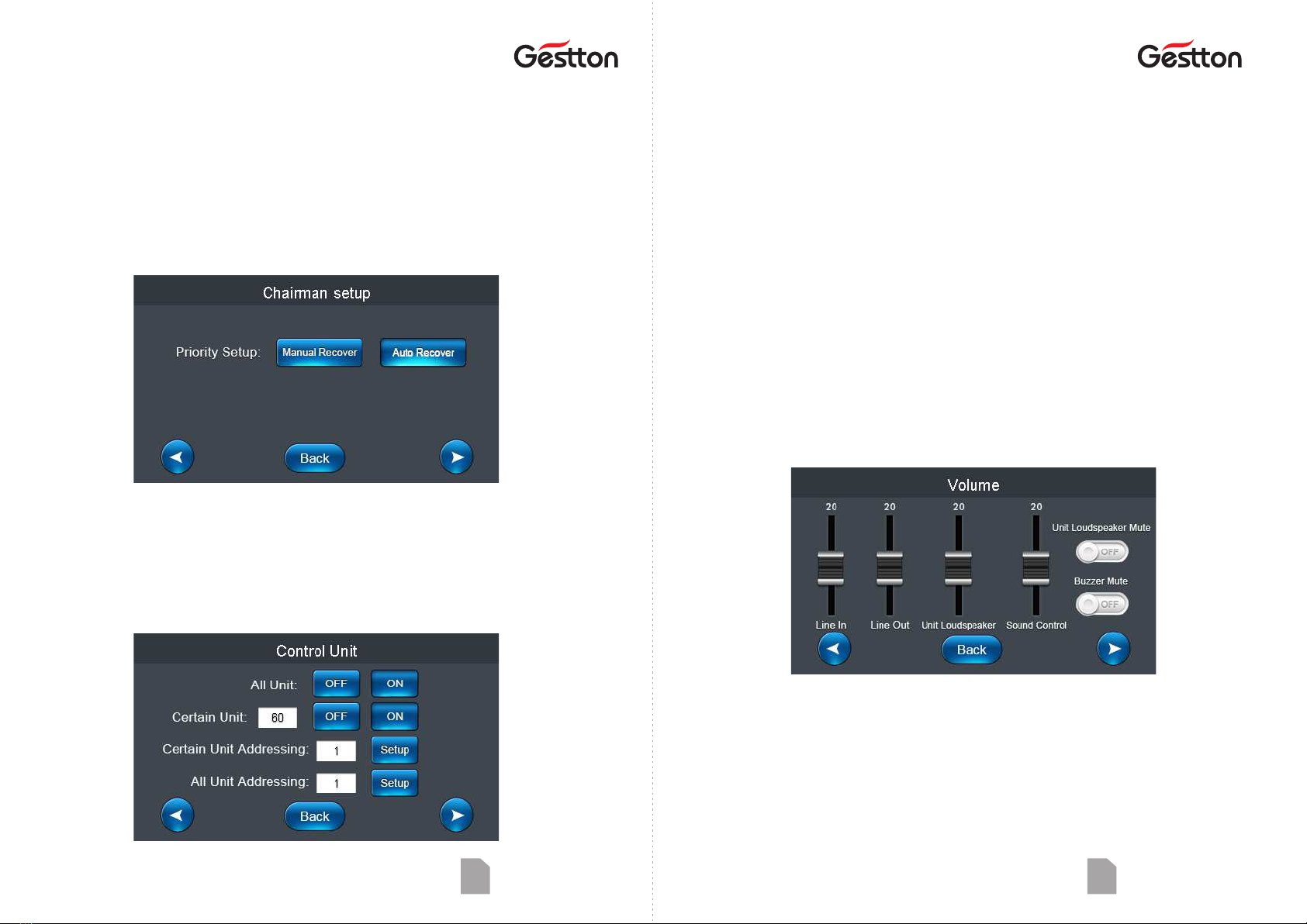
Chairman setup…………………………...8
Control unit.……………….…………..…..8
Volume......……………………………..…..9
CAMERA TRACKING
Camera tracking………………………… 10
Camera control.…………………………10
Setup preset.....…………………………11
RECORDING.................................12
SYSTEM SETUP.............................12
QUICKMARK ................................13
RESTART ......................................13
Web management system
Login page..................…………………..14
SETUP ADDRESS
Setup all unit..............…………………..14
Certain unit address…………………......15
MEETING SETUP
Queue mode..............…………………...15
Speaking qty....…….........…………….....15
Sound control.………………………………..15
Meeng mode................................15
Priority setup .................................15
Mute auto off... ..............................16
Unit ming off................................16
Sign-in select..................................16
Buzzer mute...................................16
Unit mute.......................................16
Line in/out vol................................16
CAMERA TRACKING
Camera type...............…………………..16
Camera ID........…….........……………....16
Host ID.............………………………………16
Unit ID ...........................................16
Test preset .....................................17
View preset....................................17
Delete preset .................................17
Unit light........................................17
UNIT CONTROL...............................17
UNIT NAME....................................17
SETUP SYSTEM ...............................18
SYSTEM PASSWORD........................18
SPECIFICATIONS ........................19-21
USER MANUAL | EG-6620 Digital Conference System

Product overview Product overview
USER MANUAL | EG-6620 Digital Conference System 03
Chairman unit
1. Condenser microphone capsule
Detachable design, to pickup audio
signal from speaker.
2. Mic indicator
To indicate the working status of microphone.
3. Built-in speaker
Speech signals from other microphone unit
and from controller are output from this speaker.
4. Priority key
When this key is pressed, delegate units in use
will be switched off.
5. Mic On/Off key
6. Volume control
The volume control of built-in speaker & headset.
7. Display
6
7
Delegate unit
1. Condenser microphone capsule
Detachable design, to pickup audio
signal from speaker.
2. Mic indicator
To indicate the working status of microphone.
3. Built-in speaker
Speech signals from other microphone unit
and from controller are output from this speaker.
4. Mic On/Off key
5. Volume control
The volume control of built-in speaker & headset.
6. Display
6
USER MANUAL | EG-6620 Digital Conference System
Controller Front Panel
1. USB recording port
2. TFT touch screen
3. Power switch & indicator
Controller Rear Panel
1. AC Power socket & fuse
2. Camera RS-232
3. Camera RS-485/RS-422
4. Controller RS-232 RXD
5. Video switch RS-232
6. Controller RS-232 TXD
7. Ethernet interface
8. PC USB
9. Balanced audio output
10. Line in/out, Tel in/out
11. Microphone interface
12. Extension interface
02
1 2 3 4 5 6 7 8 9 10 11 12
1 2 3

Product overview Operaon
USER MANUAL | EG-6620 Digital Conference System 05
Controller system interface
CONFERENCE CONTROL
The menu includes various parameters setup related to pre-meeng program.
CAMERA TRACKING
Configuraon window which allows operator to configure the camera posion for
each microphone.
RECORDING
The window for audio recording operaon.
SYSTEM SETUP
To configure the basic info the system such as : IP add, me, host ID etc.
QUICKMARK
QR code which allows operator to access the web management system easier.
RESTART
To reboot the system.
System connecon diagram
Note:
- Microphone units’ ID are set in factory, but users can reset the ID for each microphone
aer the installaon.
- Please ensure the system is running by required power supply.
- Avoid using the system in high humidity environment.
- It is recommended to use the system cable from manufacturer.
USER MANUAL | EG-6620 Digital Conference System 04

Operaon Operaon
Conference control – Meet mode
DISCUSSION MODE
Camera related setup, camera tracks to the
last switched on microphone unit.
CHAIRMAN MODE
Only chairman unit can be switched on.
AUTO MODE
Camera related setup, camera tracks to
microphone unit which received voice
signal.
ALL ON MODE
All microphone units can be switched on, no
limit on OPEN MIC qty.
Conference control – Meet setup
CHAIRMAN QTY
To define the qty of chairman unit.
SPEAKING QTY
Applied to delegate unit only, to define the
qty of delegate unit can open.
Conference control – Queue mode
FIFO
First in first out, under certain OPEN MIC qty, this paern applied to delegate
units. For instance, OPEN MIC qty is 2, the 1st acve unit will be switched off when
3rd unit switched on.
LIFO
Last in first out, under certain OPEN MIC qty, this paern applied to delegate
units. For instance, OPEN MIC qty is 2, the 2nd acve unit will be switched off
when 3rd unit switched on.
SOUND CONTROL ON/OFF
To allow delegate to open the microphone unit with voice.
Note: Please adjust SOUND CONTROL (at volume seng menu) at a lower level
prior to the acvaon of SOUND CONTROL funcon, and to adjust it as
needed. High sensivity level setup could lead to system overload failure
someme, please reboot the controller when system failure happened.
USER MANUAL | EG-6620 Digital Conference System 06 USER MANUAL | EG-6620 Digital Conference System 07

Operaon Operaon
USER MANUAL | EG-6620 Digital Conference System 09
ALL UNIT OFF/ON
All microphone units connected will be
switched on/off.
Note: All units can be acve when the system
set to “ALL ON MODE”.
CERTAIN UNIT ADDRESS
To allow user to allocate a specific ID to a microphone unit.
For example: A system consisted 30 mics, when an extra microphone to be included into
the system, then user can define this mic’s ID as 31 separately.
Note: Should only 1 microphone unit connected to the controller on this operaon.
Other microphone units should be disconnected during this operaon.
ALL UNIT ADDRESS
To configure the ID of all microphone units connected to the system. User can input the
inial ID, and ID will be set in ascending order to each microphone unit ll all units assigned,
then reboot the controller aer the operaon.
Conference control – Volume
LINE IN / OUT
To adjust the audio level of input / output.
SOUND CONTROL
To adjust sensivity of voice acvaon
funcon.
BUZZER MUTE
To enable or disable the buzzer of the
controller.
UNIT LOUDSPEAKER
To adjust volume of speaker of all microphone
units.
UNIT LOUDSPEAKER MUTE
Speakers on the units will be muted when this
is on.
CERTAIN UNIT OFF/ON
To switch on/off specific microphone unit by
input its ID.
USER MANUAL | EG-6620 Digital Conference System 08
AUTO OFF
To switch off the microphone when no voice
signal pickup in set me frame. 0 S means
this setup is disable.
TIME OFF
To set the me frame for the microphone unit
in acve, the unit will be switched off when
the me set is up.
Conference control – Chairman setup
MANUAL RECOVER
Delegate units will be switched off when
priority key is pressed, delegate unit can
open by pressing the ON key again.
AUTO RECOVER
Delegate units will be muted if priority key
keeps being pressed, the delegate unit will
unmuted when priority key released.
Conference control – Control unit

Operaon Operaon
USER MANUAL | EG-6620 Digital Conference System 11
Camera tracking – Setup preset
PRESET POINT
Preset point is the unit ID that assigned for the tracking posion configuraon in the pre-
setup stage.
Operaon : Operator wanted to put camera configured to track the posion of microphone
unit no. 1, user should enter number 1 at PRESET POINT then go back to
CAMERA TRACKING & CAMERA CONTROL interface to configure the tracking
posion for unit no.1 and press SAVE PRESET, then the posion info of related
camera with unit no.1 will be stored. Operator can go back to previous
operaon interfaces to configure the tracking posion for each microphone by
the same procedure.
Note: System default preset point is set to 0 as the overview of the meeng room. When no
microphone unit is in acve, camera will track to the overview posion.
TEST PRESET
To allow user to check if the tracking
preset configured correctly.
DELETE PRESET
To delete all the presets saved.
FREEZE
This funcon enables image freeze
during the camera movement.
VIEW PRESET
To allow user to check the presets saved.
UNIT LIGHT ON/OFF
To lit the indicator on the microphone to
assist operator to idenfy the unit on
operaon.
USER MANUAL | EG-6620 Digital Conference System 10
Camera tracking
CAMERA SETUP
Camera protocol: VISCA(SONY-D70)/Pelco-
D/Pelco-P (baud rate:9600)/Yaan(baud
rate:4800)
FOCUSING
Camera will adjust it automacally, but user
can adjust it manually as needed.
CAMERA NO.
Select needed camera for the tracking
posion setup.
ROTATE RATE
Rotaon speed of the camera.
Camera tracking – Camera control
The camera control window allows user to control the movement of selected camera.
Note: The system can support max.6 cameras with video switch, controller will distribute
ID to each camera automacally, user should do the manual ID setup for camera if
distribuon might fail in some cases. And user should follow the boosng order to
power on cameras first, then switch on the controller.

Operaon Operaon
USER MANUAL | EG-6620 Digital Conference System 13
QuickMark
This window allows user to access web management system by scanning the QR code.
Restart
To reboot the system.
USER MANUAL | EG-6620 Digital Conference System 12
Recording
System embedded audio recording funcon, user can record & replay through this window.
Support thumb drive capacity in FAT 32G, file format MP2@128Kbps.
System setup
SETUP IP ADDRESS
To define the IP for accessing web
management system.
HOST CONNECTION MODE
To enable or disable the extension
connecon.
RESTORE TO PRESET
The system will be restored to
factory seng.
TIME
To configure the system me.
SETUP ID
The ID assigned to controller. Each
controller should has its unique ID in
extension connecon.

Web management system Web management system
USER MANUAL | EG-6620 Digital Conference System 15
CERTAIN UNIT ADDRESS
To allow user to allocate a specific ID to a microphone unit.
For example: A system consisted 30 mics, when an extra microphone to be included into
the system, then user can define this mic’s ID as 31 separately.
Note: Should only 1 microphone unit connected to the controller on this operaon.
Other microphone units should be disconnected during this operaon.
Meeng setup
QUEUE MODE
Provide FIFO & FILO opons.
SOUND CONTROL ON/OFF
To allow delegate to open the
microphone unit with voice.
PRIORITY SETUP
Auto recover - Delegate units will be
muted if priority key keeps being pressed,
the delegate unit will unmuted when
priority key released.
Manual recover - Delegate units will be
switched off when priority key is pressed,
delegate unit can open by pressing the
ON key again.
SPEAKING QTY
Applied to delegate unit only, to define the qty
of delegate unit can open.
MEETING MODE
Discussion - camera tracks to the last switched
on microphone unit.
Auto - camera tracks to microphone unit which
received voice signal.
Chairman - Only chairman unit can be
switched on.
All On - All microphone units can be switched
on, no limit on OPEN MIC qty.
USER MANUAL | EG-6620 Digital Conference System 14
Login page
Web management system is the portal to allow operator to configure the system on
computer .
The system is embedded in the controller, no soware installaon required. User should just
enter the IP address in the browser to access the system.
IP address of the controller should be set in the same network segment as the computer
device in advance, user can check and configure the IP address from SYSTEM SETUP menu
on the controller.
Setup address
SETUP ALL UNIT
To configure the ID of all microphone units connected to the system. User can input the
inial ID, and ID will be set in ascending order to each microphone unit ll all units assigned,
then reboot the controller aer the operaon. Click SETUP to start the process , and
COMPLETE to end the process.

Web management system Web management system
USER MANUAL | EG-6620 Digital Conference System 17
TEST PRESET
To allow user to check if the tracking
preset configured correctly.
DELETE PRESET
To delete all the presets saved.
VIEW PRESET
To allow user to check the presets saved.
UNIT LIGHT ON/OFF
To lit the indicator on the microphone to assist
operator to idenfy the unit on operaon.
Unit control
UNIT CONTROL interface allows operator to check the real me status of each microphone
unit connected to the system. Unit ID will indicate in green color when it is in use, clicking
the unit ID can control the ON & OFF of corresponding unit.
Unit name
UNIT NAME interface allows operator to enter the name of aendee by clicking the unit
ID, then click“Save to device” to save as default name list. When user leaved this secon
and come back to this page, name list will not display unl clicking “Load name” to retrieve
the default list.
USER MANUAL | EG-6620 Digital Conference System 16
MUTE AUTO OFF
To switch off the microphone when no voice
signal pickup in set me frame. 0 S means
this setup is disable.
SIGN-IN SELECT (oponal)
This opon available with system with
vong funcon, user can choose either
cardless sign-in or card sign-in, to enable
the system to calculate the no. of aendee
before the kick-off of vong.
LINE IN/OUT VOL
The main volume control of system.
UNIT TIMING OFF
To set the me frame for the microphone unit
in acve, the unit will be switched off when
the me set is up.
BUZZER MUTE
To enable or disable the buzzer of the
controller.
UNIT MUTE
Speakers on the units will be muted when this
is on.
Camera tracking
CAMERA_PC & CAMERA_TOUCH are offering the same camera seng funcon, but
Camera _Touch version is opmized for mobile devices user, it has touch release me
(BUTTON TIME) adjustment opon, user may choose it to operate as needed .
CAMERA TYPE
Camera protocol: VISCA(SONY-
D70)/Pelco-D/
Pelco-P (baud rate:9600)/Yaan(baud
rate:4800)
HOST ID
The controller ID in the camera setup
CAMERA ID
Select needed camera for the tracking
posion setup.
UNIT ID
The microphone unit that needed to
configure camera tracking setup.

Web management system General Specificaons
USER MANUAL | EG-6620 Digital Conference System 19
Controller EG-6620M
Power supply
Power consumpon
Units capacity
Frequency response
SNR
Dynamic range
Harmonic distoron
Output impedance
Audio input
Audio output
Connector
Dimension
Weight
Color
AC 110 - 220V/ 50 - 60Hz
200W
100 units
30Hz - 20KHz
90dB
110dB
<0.05%
XLR:2.2K , Line out:1K
Tel in : -3dBV
Line in : 6.5dBV
MIC - RJ45 X 8
Tel. coupler - RCA X 2
Controller - RS-232 X 2
Video switch - RS-232 X 1
Camera - RS-232 X1,
12P Terminal block
Audio input - RCA X 1
Audio output - XLR X 1, RCA X 1
PC - USB X 1
Audio recording - USB X 1
Ethernet - RJ45 X 1
483 x 323 x 90mm
5.5kg
Black
Tel out : 15dBV
Line out : 0dBV
BAL out: -4dBV
USER MANUAL | EG-6620 Digital Conference System 18
Setup system
SETUP SYSTEM interface allows operator to setup the me and IP address of the system,
user should reboot the system aer the new IP address applied.
System password
The name of administrator is fixed as admin, default password is 123456. Administrator can
change password and add new user to the system, only administrator is authorized to make
changes in this secon.

General Specificaons
USER MANUAL | EG-6620 Digital Conference System 21
Microphone unit EG-6621C / EG-6621D
Power supply
Working current
Cartridge
Paern
Sensivity
Frequency response
SNR
Dynamic range
Harmonic distoron
Input impedance
Speaker
MIC length
DC 24V
45mA
Condenser
Cardioid
-50dB/Pa
100Hz - 12KHz
80dB
95dB
<0.1%
2.2K
NIL
420mm
Connector
Dimension
Weight
Color
268 x 48 x 65mm
0.95kg
Black / Silver
MIC - RJ45 X 1
Earphone - 3.5mm x 1
The specificaons are correct at the me of prinng this manual.
For improvement purposes, all specificaons for this unit, including
design and appearance, are subject to change without prior noce.
USER MANUAL | EG-6620 Digital Conference System 20
Microphone unit EG-6620C / EG-6620D
Power supply
Working current
Cartridge
Paern
Sensivity
Frequency response
SNR
Dynamic range
Harmonic distoron
Input impedance
Speaker
MIC length
DC 24V
60mA
Condenser
Cardioid
-50dB/Pa
100Hz - 12KHz
80dB
95dB
<0.1%
2.2K
3W / 4Ω
420mm
Connector
Dimension
Weight
Color
193 x 145 x 65mm
0.95kg
Black / Silver
MIC - RJ45 X 1
Earphone - 3.5mm x 1
General Specificaons
Table of contents
Other Gestton Conference System manuals