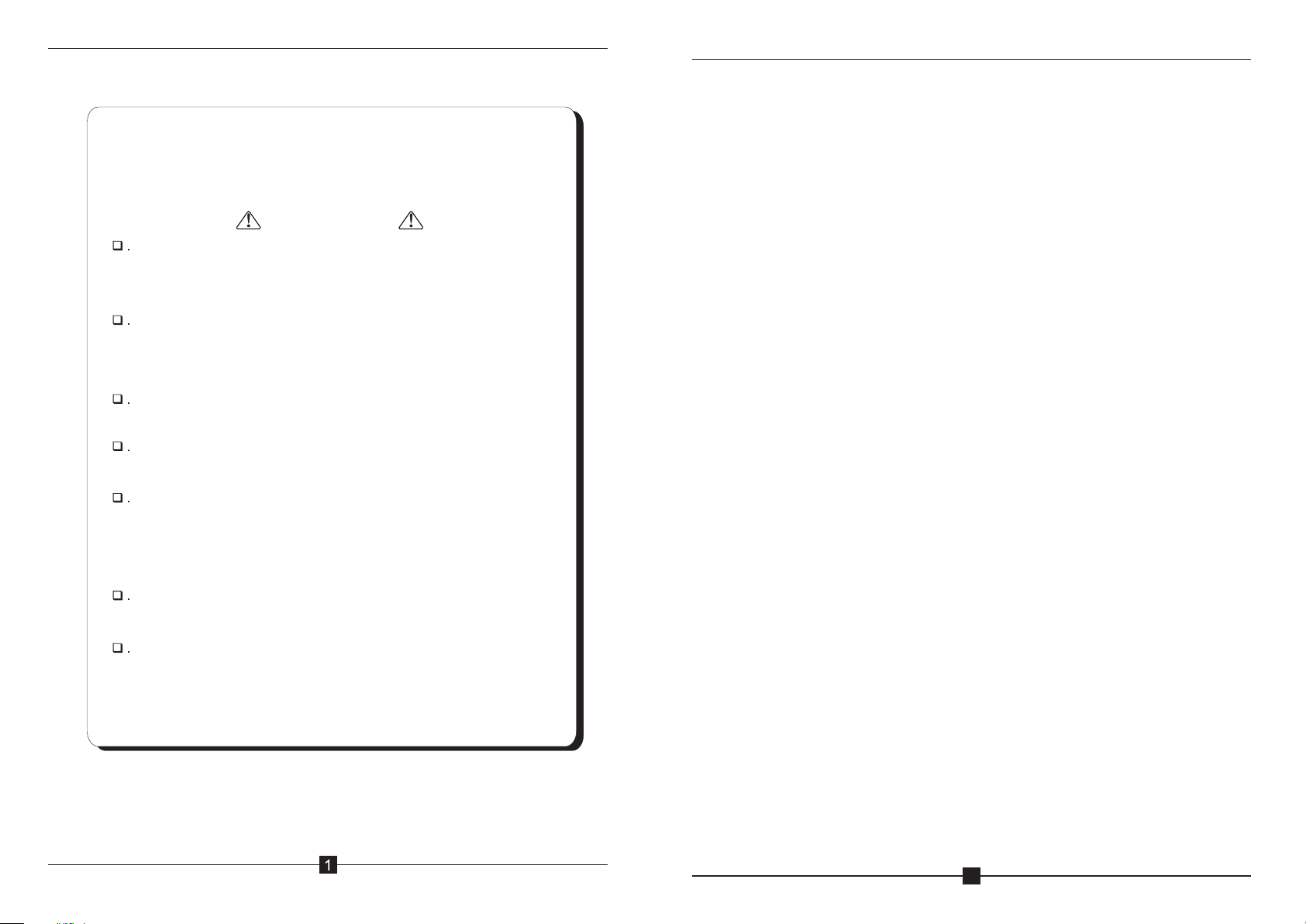
Gestton EG-6630M User manual

CAMERA TRACKING CONFERENCE SYSTEM
EG-6630M
【 】USER MANUAL

Than
Caution
Please do not scratch/band/twist/pull/heat the power cable,
otherwise, it may cause damage to the power cable & even
cause fire or electric shock.
Please do not open the casing, otherwise it may cause electric
shock. If this equipment needs checking/maintenance or
repair, please contact our representative.
Please do not retrofit this unit, otherwise, it may cause fire or
electric shock.
Please do not touch the power plug with your hands wet,
otherwise, it may cause electric shock.
If the power cable is worn out (broken or core wire exposed),
please contact our representative to get the spare part for
replacement. It may cause fire or electric shock using the worn
out power cable.
Please disconnect the power cable first & then disconnect all
the connecting cable before you move this equipment.
If this unit is not using for a long time, please remove the power
plug from the AC socket to avoid unexpected fire.
k you for using EG series conference system. Please read
below instruction carefully before using this system.
CAMERA TRACKING CONFERENCE SYSTEM
2
Contents
1.Functions.............................................. 3
2.Front Pannel............................................4
3.Rear Pannel.............................................4
4.Chairman Unit. . . . . . . . . . . . . . . . . . . . . . . . . . . . . . . . . . . . . . . . . . .5
5.Delegate Unit. . . . . . . . . . . . . . . . . . . . . . . . . . . . . . . . . . . . . . . . . . . 5
6.System Connection. . . . . . . . . . . . . . . . . . . . . . . . . . . . . . . . . . . . . .6
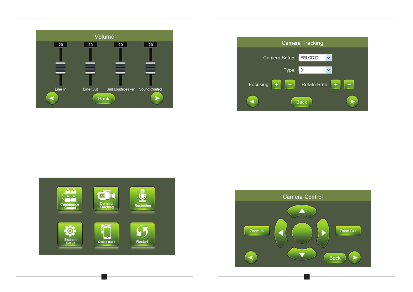
7.Touch-screen Operation Instruction........................ .7
A.Conference Control...................................7
B.Camera Tracking. . . . . . . . . . . . . . . . . . . . . . . . . . . . . . . . . . . . 11
C.Audio Recording. . . . . . . . . . . . . . . . . . . . . . . . . . . . . . . . . . . . 14
D.System Setup. . . . . . . . . . . . . . . . . . . . . . . . . . . . . . . . . . . . . . 16
E. ...........................................16
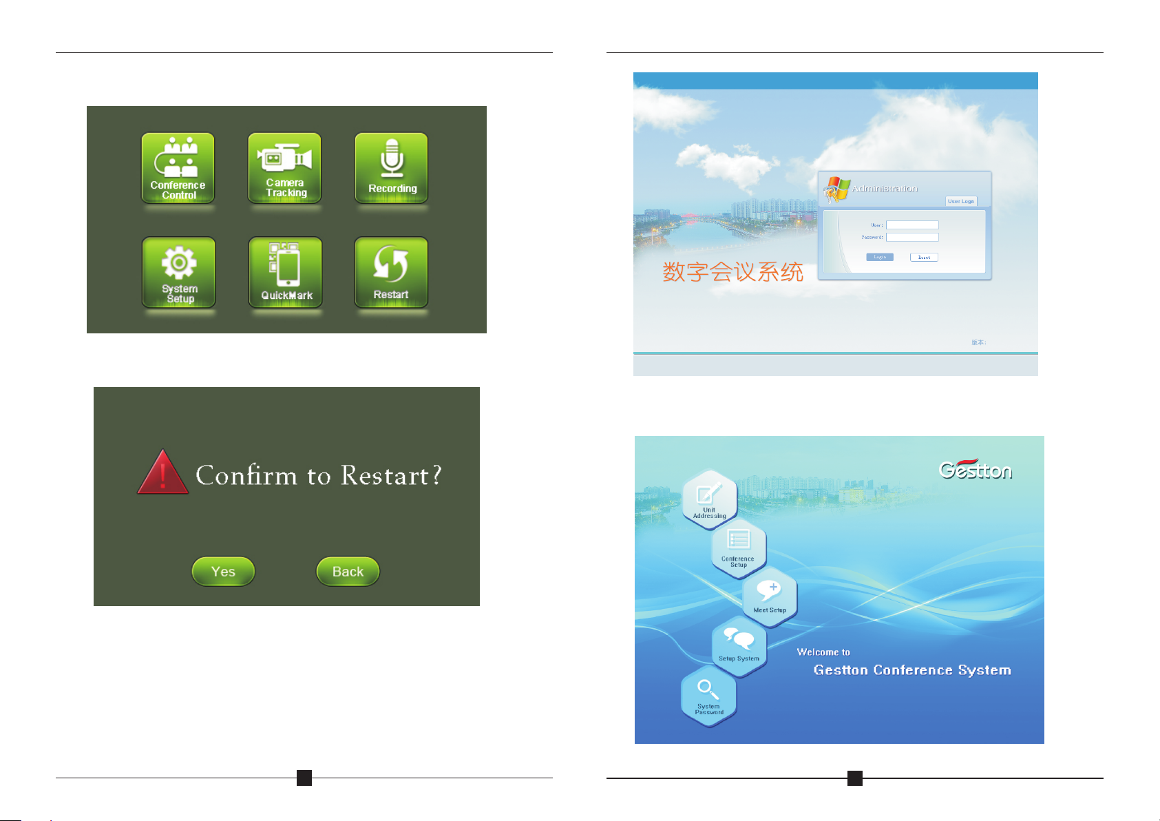
F.Restart........................................... .17
8.Webpage Operation Instruction............................17
A.Unit Addressing. . . . . . . . . . . . . . . . . . . . . . . . . . . . . . . . . . . . ..19
B.Conference Setup. . . . . . . . . . . . . . . . . . . . . . . . . . . . . . . . . . .. 20
C.Camera Tracking. . . . . . . . . . . . . . . . . . . . . . . . . . . . . . . . . . . .21
D.Conference Control..................................23
E.Setup System. . . . . . . . . . . . . . . . . . . . . . . . . . . . . . . . . . . . . . .26
F.System Password. . . . . . . . . . . . . . . . . . . . . . . . . . . . . . . . . . . .26
G.Safe Logout........................................27
9.Connecting with the Amplifier......................... .... 27
10.
QR Code
PC software instruction.................................28

CAMERA TRACKING CONFERENCE SYSTEM
3
1.Main Feature
① Fully digital circuit design;
②Main controller adopts TFT capacitive touch-screen which makes
friendly interface & easy operation.
③ With inserted control webpage, system can be controlled by portable
devices like mobilephone/Ipad/PC. This can be done without
software.
④With TCP/IP internet port to realize long-range control. It can also
be connected to central controller.
⑤ With RS232 port & USB port for setting system parameter.
⑥ Audio recording to directly. The audio file in the
can be played.
⑦ Maximum 110 microphone units can be connected to one controller.
Maximum 15 main controllers can be cascaded.
⑧ Support pelco P/D, YAAN, SONY EVI-D70 camera protocol.
⑨ Support 6-in-1-out video switcher. Maximum 6 cameras.
⑩ Maximum 5 groups of preset point for EVI-D70 can be saved to the
system.
⑪ Camera protocol can be via software by the user.
⑫ Meet mode: voice control, FIFO, chairman mode, all on mode.
⑬ Mic unit can be set time off or auto off.
⑭ With canon audio output & RCA jacks for line-in/out,Tel-in/out.
⑮ Mic unit is free from mobile interference & with hot-plug function.
thumb dirve
edited
thumb dirve
CAMERA TRACKING CONFERENCE SYSTEM
4
2.Front Panel of the Main Controller
3.Rear Panel of the Main Controller
1.TFT Touch-screen Display
Display the system configuration & working condition.
2.Power Switch
Turn on/off power for main controller
1. AC power input socket & fuse holder. Power 220V.
2. Fuse holder: 2.5A fuse.
3. Camera connection port, via RS232.
4. Camera connection port, via RS485/RS422.
5. RS-232 port for PC.
6. RS232 port, for HDMI video switcher.
7. RS-232 port for central controller.
8. TCP/IP network port: connect system with network to realize remote
control via mobilephone/Ipad/PC.
9. USB port for audio recording.
10. USB port for PC.
11. Balance Out.
12. Line-in/out & Tel-in/out
13. 4 ports for maximum 110 mic units totally.
14. Cascade port: for maximum 15 main controllers.

CAMERA TRACKING CONFERENCE SYSTEM
5
4.Chairman Unit
5.Delegate Unit
1. Mic capsule: to pick up the voice of speaker & send it to amplifier
2. Mic light loop: to indicate the working condition of the microphone
3. B
4. Priority button: to turn off all the delegate units
5.
6.
7. Display
uilt-in loudspeaker
Mic button: to turn on or turn off the microphone
Headset & built-in speaker volume control
1. Mic capsule: to pick up the voice of speaker & send it to amplifier
2.Mic light loop: to indicate the working condition of the microphone
3. Built-in loudspeaker
4. Mic button: to turn on or turn off the
microphone
5. Headset & built-in speaker volume control
6.Display
6
7
6
CAMERA TRACKING CONFERENCE SYSTEM
6
6.System Connection
Note:
The new installed system can not be used until every unit has been edited
address. Please refer to menu “Edit Address”.
Please make sure to use the required power supply.
Avoid using this system in dirty or dusty environment.
Avoid using this system in high humidity environment.

CAMERA TRACKING CONFERENCE SYSTEM
7
7.Operation for Touch-screen
A.Conference Control
Click Conference Control to enter below interface:
Queue Mode:
FIFO & LIFO: Select first in first out or for the queue.
Sound Control(ON) & Sound Control(OFF): to turn ON/OFF sound control
function. If click sound control(ON), mic unit will be turned on when
speaking to the mic.
last in first out
CAMERA TRACKING CONFERENCE SYSTEM
8
Click “back” to go back, click to go to next page.
Meet Mode:
Discussion Mode: Camera tracks the last turned on unit.
Auto Mode: Camera tracks the speaking unit.
Chairman Mode: Only chairman unit can be turned on.
All On Mode: All the units can be turned on. No limitation for speaking QTY.
Click “back” to go back, click to go to next page as below:

CAMERA TRACKING CONFERENCE SYSTEM
9
Chairman QTY: To set the limitation QTY for chairman unit.
Speaking QTY: To set the limitation for speaking units QTY.
Auto Off: To turn off the microphone automatically if the chairman or
delegate in certain time. 0S means this function is
unavailable.
Time Off: to turn off the microphone compulsively by the set certain time.
is not operated
Click “back” to go back, click to go to next page as below:
Priority Tone: To play a tone when pressing the chairman priority button.
Priority Setup: Manual Recover, Auto Recover
Manual Recover: Delegate units will be off when pressing the chairman
priority once. Delegate units need to be turned on manually by pressing the
ON/OFF button.
Auto Recover: Delegate units will be off when long pressing the chairman
priority button. Delegate units will be on again when releasing the priority
button.
Card Meeting/Cardless Meeting: When the mic units adopt IC card port, this
is to set the requirement of meeting with IC card or not.
CAMERA TRACKING CONFERENCE SYSTEM
10
Click “back” to go back, click to go to next page as below:
Control Unit
All Unit: This is to control all the unit in the main controller.
Off: Turn off all the units.
On: Turn on all the units(Note: this can only be carried out under “All On
Mode”.
Certain Unit: Turn on/off a certain unit by the related unit number.
Certain Unit Addressing: Addressing for additional unit. For example, when
there are 100 units for the system, input “101” & connect a new unit to the
system then click "Setup". The new unit address will be “101” accordingly.
Note: All the units' cables must be disconnected when setting.
All Unit Addressing: Addressing all unit by entering a starting number. For
instance starting from number 1,click “setup”, by pressing the turn on button
on each unit, the units will be set in default subsequent number. The first one
is unit number 1, followed by unit number 2, unit number will increase in an
ascending order till all units are set, and reboot main controller. (Normally
the process of unit addressing will be done prior to meeting)

CAMERA TRACKING CONFERENCE SYSTEM
11
Volume Control: To adjust volume of audio input and output, including Line
in/Line out/Unit speaker or headset/Voice control. (When voice control
function or limited speaking time mode is activated, the volume of unit voice
control is not allowed setting to the minimum level)
B.Camera
CAMERA TRACKING CONFERENCE SYSTEM
12
Click “Camera” to setup camera tracking parameter:
C a m e r a ty p e: Pe l co - D / P e l c o- P / S o n y ( ba u d r a t e : 9 6 00 )/ Ya a n (b au d
rate:4800);
Address: Select needed camera to operate.
Focusing: Focus range, the camera will adjust automatically, manual
operation can be applied when needed.
Rotate Rate: Rotation speed of the camera.
Clicking “back” to return last page, click left cursor to move backward or right
cursor to move forward to next page as below:

CAMERA TRACKING CONFERENCE SYSTEM
13
By clicking different direction button to control the movement of camera,
zoom in or zoom out button is used in specific object focusing.
Setup Preset Point:
For example, the camera is set to focus on the position of unit number 1,
enter desired preset number (here is 1) at the blank, click button “save
preset” to save setup. Click left cursor to go back previous page to setup
the rest of unit camera tracking position by following the same operation.
System default preset point number is zero (0). when all units are off,
camera will set to track this specific position, normally it is the full view of
the meeting room.
The light loop of relative units will flash during preset point setup, to allow
operator to focus on specific unit easily. After saving the setup, clicking
button “Test preset” to check if the preset point of specific unit is set
correctly.
Preview preset: To check all set preset point of units
Delete all preset point: To delete all tracking point of set units
CAMERA TRACKING CONFERENCE SYSTEM
14
When all units are set, it can be stored at this step as a proposal, multiple
proposals can store and retrieve when needed.
C. Recording
Press “Strat” to record during the meeting, thumb drive should be inserted
to the recording port at rear side of main controller to store voice data.
Clicking “back” to return last page, click left cursor to move
backward or right cursor to move forward to next page as below:

CAMERA TRACKING CONFERENCE SYSTEM
15
Audio recording pause:
The page of record playing:
The page of recording:
CAMERA TRACKING CONFERENCE SYSTEM
D. System setup
Clicking “System Setup” to setup language, IP address, time and main
controller ID.
Different ID should be allocated when more than one main controller are
cascaded. When only one main controller is in use, main controller ID
should set as 1. Default settings, set to restore the factory settings, all the
parameters of the host will be restored to factory parameters.
Quick response code
By using the scanning software of portable devices to scan the generated
QR code to instantly access the webpage operation system.
E.
16

CAMERA TRACKING CONFERENCE SYSTEM
18
User name: admin, default password:123456. ( User will log off the system
automatically after 10 minutes idle)
CAMERA TRACKING CONFERENCE SYSTEM
17
F. System Restart
Clicking “Restart” to restart the host.
Set host's IP address in the same network segment with computer
devices. For instance, when host's IP set as 192.168.1.236, user
should key in the IP address as above in explorer to login website
operation system.
8.Webpage Operation Instruction

CAMERA TRACKING CONFERENCE SYSTEM
20
B.Conference Setup
Various parameters can be set in conference setup manual as below:
FIFO & LIFO: Select first in first out or last in last out for the queue.
Speaking QTY: To set the limitation for speaking units QTY.
Sound Control(ON) & Sound Control(OFF): to turn ON/OFF sound control
function. If click sound control(ON), mic unit will be turned on automatically
when speaking toward the mic.
Meet Mode:
Discussion Mode: Camera tracks the last turned on unit.
Auto Mode: Camera tracks the speaking unit.
Chairman Mode: Only Chairman unit can be turned on.
All On Mode: All units can be turned on. No limitation for speaking QTY.
CAMERA TRACKING CONFERENCE SYSTEM
19
A.Unit Addressing
All Unit Addressing: Addressing all unit by entering a starting number. For
instance starting from number 1,click “setup”, by pressing the turn on
button on each unit, the units will be set in default subsequent number. The
first one is unit number 1, followed by unit number 2, unit number will
increase in an ascending order till all units are set, and reboot main
controller.
Certain Unit Addressing: Addressing for additional unit. For example, when
there are 100 units for the system, input “101” & connect a new unit to the
system then click Setup. The new unit address will be “101” accordingly.
Note: All the units' cables must be disconnected when setting.
(Normally the process of unit addressing will be done prior to meeting)

CAMERA TRACKING CONFERENCE SYSTEM
22
Cam e r a Ty p e : Pe l c o - D /Pe l c o - P / S o ny( b a u d rat e : 9 6 0 0 ) /Ya a n(b a u d
rate:4800);
Camera address: Select needed camera to operate.
Different ID should be allocated when more than one main controller are
cascaded. When only one main controller is in use, main controller ID should
set as 1.
Setup Preset Point:
For example, the camera is set to focus on the position of unit number 1,
enter desired preset number (here is 1) at the unit column, click button
“Save Preset” to save setup. Following the routine to complete the rest
preset point setup. System default preset point number is zero (0), when all
units off, camera will set to track this specific position, normally it is the full
view of the meeting room. When clicking “Unit Light On”, the light loop of
currently operated units will flash during preset point setup, to allow
operator to focus on the unit easily. After saving the setup, clicking button
“Test Preset” to check if the preset point of specific unit is set correctly.
CAMERA TRACKING CONFERENCE SYSTEM
21
Priority Setup: Manual Recover, Auto Recover
Manual Recover: Delegate units will be off when pressing the chairman
priority once. Delegate units need to be turned on manually by pressing the
ON/OFF button.
Auto Recover: Delegate units will be off when long pressing the chairman
priority button. Delegate units will be on again when releasing the priority
button.
Auto Off: to turn off the microphone automatically if the chairman or
delegate do not speak in certain time. 0S means this function is not
activated.
Time Off: to turn off the microphone compulsively by the set certain time.
Line In: adjust line in volume
Line Out: adjust line out volume
C.Camera Tracking
In this section, manual offered in computer version and touch screen
version for different platforms use purpose. Touch screen sensitivity
adjustment was provided in touch screen version.

CAMERA TRACKING CONFERENCE SYSTEM
24
In this section, operator can key in the name of relevant attendees by clicking
corresponding unit number, then click “Save to device”to save as default
name list. When exit this page and go back this section, name list will not
show automatically until clicking “Load name list”to retrieve default name
list. Firstly, creating a specific text file in computer, select it from file path
column, to allow preset name list store to or load from connected computer by
clicking button“Save to local”or“Load from local”To enable this
function, operator should follow below steps to configure computer:
Step A: Configure internet explorer setup:1)Tools 2)Internet Options
3)Security 4)Enter host IP into trusted sites; Uncheck “Require server
verification (https: )for all sites in this zone”
Note: If user is promptedwith error, step B should be followed after step A:
CAMERA TRACKING CONFERENCE SYSTEM
23
D.Conference Control
Conference Unit Control
Units can be controlled individually in this section. Unit status is indicated
in green when it is in use, click corresponding online unit number to turn
unit on or off.
Unit Name List Management
Step B: Configure internet explorer setup:1)Tools 2)Internet Options
3)Security 4)Custom level.Enable “ Initialize and script ActiveX
controls not marked as safe for scripting”and “Include local directory
path when uploading files to a server”

CAMERA TRACKING CONFERENCE SYSTEM
26
E.Setup System
Setup system time and IP address, system needs to restart after new IP
address is applied.
F.System Password
CAMERA TRACKING CONFERENCE SYSTEM
25

CAMERA TRACKING CONFERENCE SYSTEM
27
In this manual, administrator can add user to system and change
password. The name of administrator is fixed as admin, default password is
123456. Only administrator is authorized to make changing in this section.
As the host can be login by multiple devices at a time, thus default
administrator password should change before use, relative users should
add on the system group and distribute to corresponding personnel.
G.Logout system
Click “admin” located at upper right corner to logout system:
Adjust the volume of amplifier to the minimum level and line out at 20.
Testing personnel need to speak toward the units while adjust the volume to
an appropriate level. The position of speaker installation is important, avoid
to place microphone units toward speaker in case of howling effect occur.
9.Connect Amplifier
CAMERA TRACKING CONFERENCE SYSTEM
28
10.PC software instruction
Connect system with PC via USB port, then software will be installed
to PC automatically. Open file " Video conference system.exe", to find
below interface:
Login (defaulted password is blank) to below interface:
Two options: Connect system or connect card reader
Card reader instruction:
1)Connect card reader with PC via USB cable, then click “connect card
reader”;
2)Click “card reading” to check card information;
3)Click “card writing” to input unit number & card holder information.
4)Label seat number & card holder name to each card after card writing.

CAMERA TRACKING CONFERENCE SYSTEM
29
CAMERA TRACKING CONFERENCE SYSTEM
30
Voting system instruction:
Connect EG-6630M main controller with PC via USB cable, then click
“connect host”:
User Management
To set up user name, user password & user department.
Conference System
Main controller setup
Click “host setting”-“all host parameter setup”to find below interface:
1)Select the number of host(main controller) first, then select “activated” of
status for the chosen host;
2)Input the amount number of delegate units under “batch new”, then click
“batch new” to generate delegate list;
3)Input/modify delegate name then save it; Delegate name can be
displayed in the “Realtime meeting”only.
4)Input registration number to the blank below “registration number” to set
attendees QTY of the meeting.
5)When cascade multi controller, select the corresponding number of host
& set all the parameter. Each time activating/deactivating host, the
software need to be restarted after finishing setup.
6)Input maximum 5 candidates name for election if necessary. Each
number of name in the software correspond with number on the delegate
unit.

CAMERA TRACKING CONFERENCE SYSTEM
31
CAMERA TRACKING CONFERENCE SYSTEM
32
Wireless voting system setup: This system can work with wireless voting
system.
Firstly set the host number in the software corresponding to host ID of
wireless voting system main controller(from1-15) and activate host.
Setup for wireless voting system in the software is the same as setup for
conference system. Delegate amount & attendees QTY must be set.
Please note that host ID for wireless voting system should be different with
host ID for conference system.
Line Checking
This is to check online unit of conference system & wireless voting system.
Unit Management
This is to edit & view delegate's information.

CAMERA TRACKING CONFERENCE SYSTEM
33
CAMERA TRACKING CONFERENCE SYSTEM
34
Venue Design
Venue Layout: Setup a simulative conference hall for the meeting.
Realtime Meeting: Check unit status & control meeting.
Venue Layout
1) Parameter Setting: setup size for icon & setup spacing for quick layout
setup;
2) Quick set up one: input attendee QTY & QTY of each line to get layout;
3) Quick set up two: input QTY of each line & column to get layout;
4) Save current layout setup, then enter Realtime Meeting to check unit
status.
Click certain icon to turn on/off unit in interface of Realtime Meeting.
Meeting Mode

CAMERA TRACKING CONFERENCE SYSTEM
35
CAMERA TRACKING CONFERENCE SYSTEM
36
Meeting Mode:
Meeting:
Card: to hold the meeting with IC card.
Cardless: to hold the meeting without IC card
Unit Speaker: To turn on/off speaker
Buzzer: To turn on/off buzzer in the main controller.
Priority Tone: To turn on/off the tone when using chairman priority.
Speaking QTY: to setup the maximum of speaking units.
Speaking QTY: to setup the maximum QTY of speaking units(including
Chairman).
Chairman QTY: to setup the maximum QTY of speaking chairman unit.
Note: Chairman QTY can be more than speaking QTY.
Advanced Setup
Defaulted password is blank.
Discussion Mode: Camera tracks the last turned on unit.
Auto Mode: Camera tracks the speaking unit.
Chairman Mode: Only Chairman unit can be turned on.
All On Mode: All the units can be turned on. No limitation for speaking QTY.
Queue: Select first in first out or last in last out for the queue.
Voice Control: to turn ON/OFF sound control function. If click sound
control(ON), mic unit will be turned on when speaking to the mic.
Priority Setup: Manual Recover, Auto Recover
Manual Recover: Delegate units will be off when pressing the chairman
priority once. Delegate units need to be turned on manually by pressing
the ON/OFF button.
Auto Recover: Delegate units will be off when long pressing the chairman
priority button. Delegate units will be on again when releasing the priority
button.
Auto Off: to turn off the microphone automatically if the chairman or
delegate do not speak in certain time. 0S means this function is not
activated
Time Off: to turn off the microphone compulsively by the set certain time.
All unit addressing: addressing all unit by entering a starting number. For
instance starting from number 1,click “setup”, by pressing the turn on
button on each unit, the units will be set in default subsequent number.
The first one is unit number 1, followed by unit number 2, unit number will
increase in an ascending order till all units are set, and reboot main
controller. (Normally the process of unit addressing will be done
during installation, no need to setup during operation)
Certain Unit Addressing: Addressing for additional unit. For example, when
there are 100 units for the system, input “101” & connect a new unit to the
system then click Setup. The new unit address will be “101” accordingly.
Note: All the units' cables must be disconnected when setting.
Camera Tracking
Host ID setup: Firstly connect only one controller to PC, then revise host ID
and restart controller.
C a m e r a ty p e : P e l c o- D / P e lc o - P / So n y ( b a u d ra t e : 9 60 0 ) / Ya a n ( b a u d
rate:4800);
Camera address: Select needed camera to operate.
Different ID should be allocated when more than one main controller are
cascaded. When only one main controller is in use, main controller ID should
set as 1.
Setup preset point:
For example, the camera is set to focus on the position of unit number 1,
enter desired preset number (here is 1) at the unit column, click button “Save
Preset” to save setup. Following the routine to complete the rest preset point
setup. System default preset point number is zero (0), when all units off,
camera will set to track this specific position, normally it is the full view of the
meeting room. When clicking “Unit Light On”, the light loop of currently
operated units will flash during preset point setup, to allow operator to focus
on the unit easily. After saving the setup, clicking button “Test Preset” to
check if the preset point of specific unit is set correctly.

CAMERA TRACKING CONFERENCE SYSTEM
37
CAMERA TRACKING CONFERENCE SYSTEM
38
Voting System
Voting Management
To setup attendee data for sign in. Attendees must sign in first, so that they
can vote.
Proposal & Voting
Setup new voting proposal in below interface. Input subject, content, & other
voting data to the proposal. Voting setting can limit certain attendee to vote.
After setup new proposal, click “Save” to generate proposal.
Multiple proposals can be set in the software. Each proposal can be selected
to vote after sign in.
Table of contents
Other Gestton Conference System manuals
Popular Conference System manuals by other brands

Biamp
Biamp TesiraFORTÉ AVB VT4 System design guide

COBHAM
COBHAM EXPLORER 540 Setup guide

Cisco
Cisco Aironet 1000 Series Hardware Options & Upgrade Guide

PTN
PTN D-3002 user manual

BEANAIR
BEANAIR BeanDevice AN Series quick start

Cisco
Cisco Unified MeetingPlace Web Conferencing Installation and upgrade guide