GEV GSL 30 Guide

EDIZIONE 01/11
LIBRETTO DI MANUTENZIONE
E
PARTI DI RICAMBIO
OPERATING MANUAL
AND
SPARE PARTS LIST
SOFFIANTI CANALI LATERALI GSL
SIDE CHANNEL BLOWERS GSL
GENERAL EUROPE VACUUM Srl
VIA DEL COMMERCIO, 9
20090 BUCCINASCO (MI) ITALY
TEL. ++39 02 48841120
FAX ++39 02 4453957
http://www.gevac.com

2 di 19
DESCRIZIONE ………………………………….PAG.
CONTENT PAGE
1. SICUREZZE 3
SAFETY REQUIREMENT
2. INSTALLAZIONE 6
INSTALLATION
3. OPERATIVITA’ 11
OPERATION
4. MANUTENZIONE 11
MAINTENANCE
5. SOLUZIONE PROBLEMI 12
TROUBLE-SHOOTING
6. RICAMBI 14
PART LIST

3 di 19
WARNING
ATTENZIONE
1. Le soffianti GSL sono costruite per operare all’interno in ambienti privi di acqua e
polveri.
This unit is designed to operate indoors, and is an environment that is a water-free and dust-free.
2. Per evitare il danneggiamento della soffiante evitare cadute durante il trasporto.
To avoid damaging this device, it must be absolutely prevented from dropping during transportation.
3. Evitare l’installazione della soffiante senza aver preventivamente letto attentamente
le istruzioni contenute in questo manuale.
It’s not allowed to install and operate this device before reading the instruction thoroughly.
4. Per ragioni di sicurezza, non modificare o riparare le parti rotanti della soffiante.
For safety reason, please don’t modify or repair the rotating part of this device.
5. Il produttore ha facoltà di modificare la soffiante senza preavviso.
The manufacturer has the right to modify the product without notice.
6. Questa soffiante è unicamente un componente, deve essere installata in una
macchina o parte di essa che sia conforme alle direttive 98/37/CE.
Non si ravvisano infrazioni se il prodotto o il macchinario è conforme con la
EN60204-1.
This unit is only a component, it must be installed in a machine or part of a machine which meets
the terms of the machine directive 98/392/CE.Commission will not occur until the end product or
machinery conforms with the EN60204-1.

4 di 19
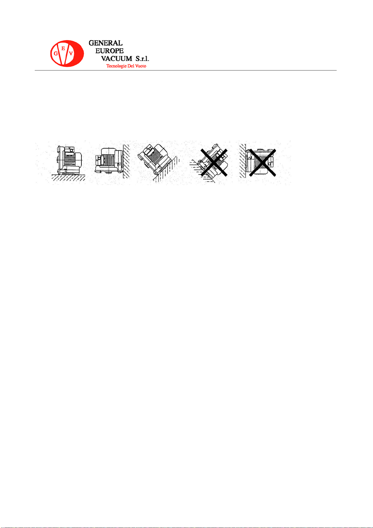
1. SICUREZZE: WARNING
SAFETY REQUIREMENTS : ATTENZIONE
1.1 La temperatura massima ammissibile dell’ambiente e dell’aria in aspirazione
+ 40° C.
The maximum permissible ambient and air temperature at the intake is +40°C.
1.2 La massima pressione ammissibile nella soffiante : 2 bar abs. A questa pressione
l’operatività della stessà ne risulta considerevolmente indebolita.
Max. permissible pressure in the device : 2 bar abs. At this pressure, the operation of the device
may be considerably impaired.
1.3 Tutte le operazioni, quali : trasporto, installazione, manutenzione e risoluzione dei
problemi devono essere curati da un responsabile qualificato.
All the works of transportation, installation, maintenance and troubleshooting must be executed by a
responsible, qualified personnel.
1.4 La soffiante deve funzionare seguendo le istruzioni del presente manuale.
This device must be set up according to this instruction manual.
1.5 La messa a terra deve essere collegata adeguatamente.
The grounding wire must be connected well accordingly.
1.6 I cavi condotti al connettore per la fornitura elettrica devono essere
appropriatamente dimensionati ed avere protezione sui cavi stessi nei collegamenti
terminali. Se questa manca è possibile il verificarsi di scosse o incendi.
The lead wires as a conductor to the power supply should be properly sized and have strain relief to
the wires at the connection terminals. If this is failed , electric shock and fire will be possible.
1.7 Mentre la soffiante è in funzione, fare attenzione ai particolari rotanti, come la
ventola di raffreddamento, e non collegarsi alla soffiante tramite aspirazione e
scarico.
While rotating, human body must keep away from the rotating portion such as the Cooling Fan and
do not reach into the device through the intake or outlet.
1.8 Una volta che la potenza elettrica è stata interrotta. L’interruttore di potenza deve
essere spento immediatamente.
Once the power electricity was interrupted, the power switch must be turned off immediately.
1.9 Se la soffiante non entrasse in funzione nel giro di 15 secondi da quando si è
azionato l’interruttore, spegnere immediatamente l’apparecchio e ricontrollarlo.
If the device couldn’t accelerate up to its rated speed in 15 seconds from the power switch turned
on, please turn off the power immediately and check it carefully.
1.10 La soffiante deve essere spenta prima di spostarla, farne manutenzione o
riparazione. Noterete che, a causa d’inerzia di rotazione, dopo lo spegnimento, la
soffiante deve essere lasciata funzionare per alcuni minuti.
The power supply must be turned of before moving, maintaining, or repairing this device. Please
note tha, due to rotating inertia, the device may continue running several minutes after power turned
off.
1.11 Le soffianti sono utilizzate esclusivamente per trattare o convogliare aria
priva di polvere, non-combustibile, non-corrosiva e gas non incendiabili e vapori.
These devices are only used to handle or conveying dust-free air, non- combustible, non-corrosive
and non-explosive gases, vapors.
1.12 L’aspirazione deve essere appropriatamente alloggiata e protetta in modo
che particelle sporche o solide non possano essere aspirate.
The intake must be properly sited and covered so that no dirt or solid particles can be sucked in.

5 di 19
1.13 Quando la soffiante opera ad una condizione di pressione ammissibile
alta,per prevenirne il surriscaldamento del motore si consiglia di installare una
valvola di rilascio pressione.
When the device is operated at impermissible high pressure condition, a suitable pressure-relief
valve must be used to prevent overheating of motor.
1.14 Il coperchio terminale è utilizzato per prevenire il contatto e direzionare il
flusso di ventilazione aria, non deve essere rimosso altrimenti il motore si
surriscalderà.
The End Cover is used to prevent contact and direct the cooling air flow, can not be removed;
otherwise the motor will get overheating.
1.15 Un protettore termico di tipo pilota, sarà disponibile su richiesta cliente.
Questo protettore dovrà essere collegato esternamente con un magnetostato che è
utilizzato per controllare la potenza in acceso / spento.
A Pilot type of Thermal Protector will be available according to custumer’s request.
This protector should be externally connected with a Magnetic Switch which is used to control the
power input ON/OFF.
1.16 Questa soffiante è disegnata per operare in continuata. Nel caso di
operatività non in continuata ad alta temperatura ambientale,controllare la fattibilità
( pressione massima ammessa ) contattando il responsabile tecnico del fornitore.
This device is designed for continuos operation, in case of on-continuous running or high ambient
temperature, checking suitability ( maximum permissible temperature ) with the representatives of
manufacturer.

6 di 19
2. INSTALLAZIONE
INSTALLATION
CASING COVER COPERTURA COPERCHIO
COVER COPERCHIO
STATOR ASSEMBLY ASSEMBLAGGIO STATORE
SILENCER SILENZIATORE
FOOT BASE
TERMINAL BOX SCATOLA MORSETTIERA
FAN COVER COPERCHIO VENTOLA
BLOWER PORT SCARICO
SUCTION PORT ASPIRAZIONE
2.1 UTILIZZO
APPLICATION
2.1.1 La soffiante è utilizzata per il trattamento di gas e aria non infiammabili, non
corrosivi e non combustibili. La temperatura gas e ambiente deve essere inferiore a 40
° C.
This device is used to handle non-combustible, non-corrosive and non-explosive gases and air. The
ambient or gas temperature should be less than +40°C.
2.1.2Particelle solide o sporcizia devono essere appropriatamente filtrate prima che
entrino in aspirazione.
Dirt and solid particles must be filtered before entering intake of device.
2.1.3La soffiante non deve funzionare con aspirazione o scarico chiusi.
These devices must not be operated with closet intake or outlet.
2.1.4 La pressione ammissibile per operare in continuata è indicata nella tabella 1 .
The permissibile pressure for continuos operation is shown in the table 1.

7 di 19
Tabella 1 / Table 1
MODEL
kW
50/60Hz
Max.Vacuum
Mbar
50/60Hz
Max.Blower
Mbar
50/60Hz
Max.Vacuum
Air Flow
m³/h
50/60Hz
Max.Blower
Air Flow
m³/h
50/60Hz
Single Phase
GSL 30
0.22/0.28
60/70
65/85
58/66
52/66
GSL 70
0.38/0.42
92/125
100/140
74/90
75/96
GSL 100
0.80/0.90
150/160 160/160 144/170
144/180
Three Phase
GSL 250
1.50/1.75
210/200
220/200
210/230
210/250
GSL 250
2.20/2.55
220/240
270/270
210/230
210/250
GSL 300
3.00/3.45
250/270
280/270
306/370
306/370
GSL 400
5.5/6.3
270/310
300/280
510/600
510/600

8 di 19
2. 2 INSTALLAZIONE:
INSTALLATION
2.2.1 La soffiante a canale laterale può essere installata in qualsiasi direzione ma se
montata in verticale il lato motore deve essere verso l’alto.
The Ring Compressor can be installed in any direction, but when mounted vertically, the motor
side should be upward.
2.2.2.Per evitare le vibrazioni, la soffiante deve essere installata su di un basamento
rigido.
To avoid vibration the unit must be mounted on a rigid base.
2.2.3Per assicurarne un perfetto funzionamento di raffreddamento, le tolleranze
minime dal muro tra la parte anteriore copertura coperchio e coperchio ventola devono
essere le seguenti :
To ensure perfect cooling, the minimum clearances between the Front ( Casing ) Cover & Fan
Cover and the walls should be for:
Casing Cover / Fan Cover
GSL 30 / GSL 70 / GSL 100 / GSL 250 : 20mm / 35mm
GSL 300 : 30mm / 55mm
GSL 400 : 40mm / 55mm
assicuratevi che non ci siano ostacoli nel sistema di ventilazione.
Make sure too, no obstructions in the cooling air flow system.
2.2.4.Qualsiasi materiale infiammabile deve essere tenuto lontano dall’unità
Any flammable materials must be kept away from the unit.
2.2.5 Aria e gas devono essere filtrati prima di entrare nella aspirazione con un filtro in
Linea.
Air and gases should be filtered before entering the intake by an intake or inline filter.
2.2.6 Per ridurre la rumorosità, silenziatori aggiuntivi sono opzionali.
To reduce noise, additional silencers are optional.

9 di 19
2.3 COLLEGAMENTI ELETTRICI :
ELECTRIC CONNECTION :
ATTENZIONE :Nessun lavoro di collegamento è concesso prima di aver
disconnesso la potenza elettrica.
WARNING : No connecting work is allowed before the electric power
disconnected.
2.3.1. il voltaggio deve essere identico a quello indicato in targa.
The supplied power voltage must be the same as the rating stated on the name-plate.
2.3.2 Selezionare il circuito appropriato per associarlo alla corrente di targa motore
Select the correct circuit breaker to match the motor’s rated current.
2.3.3 Si consiglia con l’utilizzo del magnetostato ,di programmare il valore corrente motore
a 0.91 volte.
We recommended when using the magnetic switch, the settino value of electric current is the motor’s
rated current of 0.91 times.
2.3.4 Collegamento relè termici:
Thermal protectors connection :

10 di 19
2.3.5 Il conduttore di protezione terra deve essere connesso ai terminali terra
The protective earth conductor must be connected to the grounding terminal.
2.3.6 I cavi principali devono essere collegati secondo lo schema sottostante alla scatola
morsettiera.
The lead wires must be connected according to the diagram attached on the terminal box.
Monofase per
Single Phase for GSL 30 / GSL 70
Monofase per
Single Phase for GSL 100
Trifase per
Three Phase for GSL 250 / GSL 300 / GSL 400

11 di 19
3. FUNZIONAMENTO
OPERATION
3.1 Queste apparecchiature devono ruotare con senso di rotazione come da freccia
stampigliata sul coperchio.
These devices must be rotated in the “Arrow” direction marked on the casing.
3.2 Per il trifase, cambiare la direzione può essere fatta modificando le 2 linee
alimentazione elettrica
For three phase, changing direction may be done by exchanging any two of the lines of power
Input.
3.3 Queste apparecchiature dovrebbero funzionare con flusso aria e pressione entro i
limiti elencati nella tabella 1.
These devices should be operated with the air flow and pressure within the permitted range listed
in the table 1.
3.4 Per evitare il funzionamento fuori dai parametri consentiti, è consigliabile applicare
una valvola di sovrapressione o ritegno.
To avoid operatine over the permitted range, the pressure or vacuum relief is
recommended.
4. MANUTENZIONE
MAINTENANCE
ATTENZIONE : Nessun lavoro di manutenzione è concesso
prima che sia scollegata l’elettricità.
WARNING : No maintaining work is allowed before the electric
power off.
4.1 Per mantenere una prestazione di raffreddamento ottimale, è necessario pulire
l’interno e l’esterno dei coperchi ventola e togliere lo sporco e la polvere
periodicamente, altrimenti il motore potrebbe bruciarsi.
To maintain a good cooling performance, it’s necessary to clean the inside and outside of the Fan
Cover to remove dirt and dust in a period of time; otherwise the motor might be burnt.
4.2 I cuscinetti, la guarnizioni e i silenziatori sono soggette a usura, queste parti
dovrebbero essere sostituite con delle nuove dove necessario.
The bearing, oil seal nd silencers are subject to wear, these parts should be replaced with new
ones as necessary.

12 di 19
5. SOLUZIONE PROBLEMI :
Problemi/Fault
Cause/Cause
Rimedi/Remedy
Il motore non funziona
. non c è tensione
. i 2 cavi tensione sono aperti
. interruttore tensione o statore
motore difettosi
. avvolgimento motore aperto
. protezione o circuito protettivo
aperto
. dare tensione
. controllare la tensione cavi
. cambiare interruttore o statore
motore
. cambiare avvolgimento motore
. cambiare protezione o fissare il
circuito
Motor does not run and
without humming noise
-No power
-Two power cords opened
-Power switch or stator defected
-Motor winding opened
-Protector or protecting circuit
opened
-Supply power
-Check the power cord
-Change the power switch or stator
-Change the motor winding
-Change the protector or fix the
protecting circuit
Il motore funziona ed è
rumoroso
. un cavo potenza aperto
. interuttore tensione o statore
motore difettosi
. avvolgimento motore aperto
. cuscinetti difettosi
. girante intasata
. girante incastrata contro
coperchio o copertura
. condensatore ( monofase )
difettoso
. controllare il cavo tensione
. cambiare interruttore tensione
e statore motore.
. rifare avvolgimento
. cambiare i cuscinetti
. pulire la girante
. controllare la girante
.Cambiare il condensatore
Motor does not run with humming
noise
-One power cord opened
-Power switch or stator defected
-Motor winding opened
-Bearing defected
-Impeller jammed by foreign
material
-Impeller jammed against casing or
cover
-Capacitor (single phase) defected
-Check the power cord
-Change the power switch or stator
-Change a new motor winding
-Change bearing
-Clean the impeller
-Adjust the impeller
-Change a new capacitor

13 di 19
Normale funzionamento,
surriscaldamento, protezione e
circuito protezione entra in
funzione ripetutamente
. motore in sovraccarico
.Circuito breve nell’avvolgimento
. ventola intasata
. ridurre la pressione di
esercizio, installare la pressione
o dispositivo rilascio vuoto,
pulire il filtro, coperchio ventola,
silenziatore e tubazioni
. cambiare avvolgimento motore
. pulire o sistemare la ventola.
Normal running, over heating,
protector or protection circuit trips
repeatedly.
-Motor overloaded
-Short-circuit in the winding
-Impeller jammed
-Reduce operating pressure, Install
the pressure or vacuum relief,
clean filter fan cover silencer or
pipes
-Change a new motor winding
-Clean or adjust the impeller
Scarso vuoto
. soffiante troppo piccola
. frequenza di tensione errata
. direzione di rotazione errata
. tenute difettose
. perdita d’aria nel sistema
. piazzare soffiante più grande
. sistemare la tensione
. cambiare la rotazione
. cambiare le tenute
. controllare il sistema e renderlo
stagno
Weak vacuum
-Compressor too small
-Wrong power frequency
-Wrong directin of rotation
-Oil seal defected
-Air leakage in the system
-Change larger compressor
-Adjust power frequency
-Change direction
-Change a new oil seal
-Check the system and make
air-tight
Rumorosità insolita
. silenziatore sporco
. cuscinetti difettosi . pulire il silenziatore
. ingrassare i cuscinetti o
sostituirli con nuovi
Abnormal noise
-Silencer dirty
-Bearing defected
-Clean silencer
-Regrease bearing or change a
new bearing

14 di 19
7. LISTA COMPONENTI :
Fig.
No.
Name of part
GSL 30
GSL 70
1-1 Bullone / Bolt 6 6
1-2 Copertura coperchio / Casing cover 1 1
2-1 Bullone / Bolt 1 1
2-2 Rondella / Washer 1 1
2-3 Piastra di trattenimento / Plate retaining 1 1
2-4 Girante / Impeller 1 1
2-5 Spessore / Shim assembly 1 1
2-6 O-ring / Collar 1 1
3-1 Vite / Screw 2 2
3-2 Coperchio cuscinetto / Bearing cover 1 1
3-3 Anello di tenuta / Shaft seal 1 1
3-4 Corpo soffiante / Casing 1 1
4-1 Statore motore / Stator assembly 1 1
4-2 Bullone / Bolt 4 4
4-3 Coperchio motore / End housing 1 1
4-4 Ventola / Fun 1 1
4-5 Coperchio ventola / Fan cover 1 1
4-6 Vite / Screw 3 3
4-7 Dado / Nut 4 4
4-8 Rondella / Spring Washer 4 4
4-9 Vite / Screw 5 5
4-10 Dado / Nut 5 5
5-1 Cuscinetto / Bearing 1 1
5-2 Chiavetta / Key 1 1
5-3 Rotore del motore / Motor rotor 1 1
5-4 Cuscinetto / Bearing 1 1
5-5 Rondella elastica / Wave washer 1 1
6-1 Coperchio condensatore / Capacitor cover 1 1
6-2 Vite / Screw 2 2
6-3 Vite / Screw 2 2
6-4 Supporto condensatore / Clip 1 1
6-5 Vite / Sleeve 1 1
6-6 Condensatore / Capacitor 1 1
6-7 Tappo passante isolante / Bushing 1 1
7-1 Coperchio morsettiera/Cover for terminal box 1 1
7-2 Guarnizione / Gasket 1 1
7-3 Guarnizione / Gasket 1 1
7-4 Scatola morsettiera/Under part of terminal box 1 1
7-5 Rondella / Spring Washer 1 1
7-6 Vite messa a terra / Earthing screw 1 1

15 di 19
7-7 Tappo passante isolante / Bushing 1 1
7-8 Vite / Screw 1 1
7-9 Morsettiera / Terminal board 1 1
7-10 Vite / Screw 2 2
7-11 Dado / Nut 12 12
7-12 Piastrine per cablaggio / Terminal board 2 2
7-13 Morsetto / Terminal clip 4 4
7-14 Vite / Screw 1 1
8-1 Corpo silenziatore / Silencer assembly 2 2
8-2 Filtro silenziatore / Silencer retaining 2 2
8-3 Coperchio silenziatore / End cover 1 1
8-4 Vite / Screw 6 6
8-5 Guarnizione / Gasket 2 2
8-6 Flangia filettata / Threaded flange 2 2
8-7 Bullone / Bolt 4 4
8-8 Tubo flangiato / Hose flange 2 2
GSL 30 / GSL 70

16 di 19
Fig.
No.
Name of part
GSL
100
GSL
250
GSL
300
GSL
400
1-1 Bullone / Bolt 6 7 8 8
1-2 Copertura coperchio / Casing cover 1 1 1 1
1-3 Vite / Screw 3 3 4 4
1-4 Rondella / Washer 3 3 4 4
1-5 O-ring 3 3 4 N/A
1-6 O-ring N/A 1 1 N/A
2-1 Bullone / Bolt 1 1 1 1
2-2 Rondella / Spring Washer 1 1 1 1
2-3 Piastra di trattenimento / Plate retaining 1 1 1 1
2-4 Cuscinetto / Bearing 1 1 1 1
2-5 Coperchio cuscinetto / Bearing cover 1 1 1 1
2-6 Girante / Impeller 1 1 1 1
2-7 O-ring / Collar N/A 1 1 N/A
3-1 Corpo soffiante / Casing 1 1 1 1
3-2 Golfare / Eyebolt N/A 1 1 1
3-3 Anello tenuta cuscinetto / Felt ring 1 1 1 N/A
3-4 Anello di tenuta / Shaft seal 1 1 1 1
3-5 Dado quadro / Square nut 1 N/A N/A N/A
3-6 Vite / Sleeve N/A 1 1 1
3-7 Base / Foot 1 1 1 1
3-8 Dado quadro / Square nut 2 2 2 N/A
3-9 Bullone / Bolt 2 2 2 2
3-10 Rondella / Spring Washer 1 1 1 1
3-11 Bullone / Bolt 1 1 1 1
4-1 Statore motore / Stator assembly 1 1 1 1
4-2 Coperchio motore / End housing 1 1 1 1
4-3 Bullone / Bolt 3 4 4 4
4-4 Bullone / Bolt 3 4 4 4
4-5 Ventola / Fun 1 1 1 1
4-6 Coperchio ventola / Fan cover 1 1 1 1
4-7 Vite / Screw 3 3 3 4
4-8 Dado / Nut N/A N/A 4 4
4-9 Dado / Nut N/A N/A 4 4
5-1 Chiavetta / Key 1 1 1 1
5-2 Rotore del motore / Motor rotor 1 1 1 1
5-3 Cuscinetto / Bearing 1 1 1 1
5-4 Rondella elastica / Wave washer 1 1 1 1
6-1 Cavo elettrico / Cable gland 1 N/A N/A N/A
6-2 Vite / Screw 2 N/A N/A N/A
6-4 Supporto condensatore / Clip 2 N/A N/A N/A
6-6 Corpo condensatore / Capacitor assembly 1 N/A N/A N/A

17 di 19
7-1 Coperchio morsettiera/Cover for terminal box 1 1 1 1
7-2 Vite / Screw 2 2 4 4
7-3 Guarnizione / Gasket 1 1 1 1
7-4 Morsettiera / Terminal board 1 1 1 1
7-5 Dado / Nut 12 12 12 12
7-6 Piastrine per cablaggio / Terminal plate 3 3 3 3
7-7 Vite messa a terra / Earthing screw 1 1 1 1
7-8 Rondella / Spring Washer 1 1 1 1
7-9 Vite / Screw 4 4 4 4
7-10 Scatola morsettiera/Under part of terminal box 1 1 1 1
7-11 Guarnizione / Gasket 1 1 1 1
7-12 Vite / Screw 5 6 6 6
7-13 Dado / Nut 5 6 6 6
7-14 Morsetto / Terminal clip 6 6 6 6
7-15 Vite / Screw 2 2 2 2
7-16 Pressacavo / Plug 0 1 1 1
8-1 Guarnizione / Gasket 2 2 2 2
8-2 Filtro silenziatore / Silencer retaining 2 2 2 2
8-3 Corpo silenziatore / Silencer assembly 2 2 2 2
8-4 Carcassa silenziatore / Silencer casing 2 2 2 2
8-5 Bullone / Bolt 4 4 4 4
8-6 Bullone / Bolt 4 4 4 6
8-7 Flangia filettata / Threaded flange N/A 2 2 2
8-8 Tubo flangiato / Hose flange 2 2 2 N/A
8-9 Guarnizione / Gasket 2 2 2 2

18 di 19
GSL 100

19 di 19
GSL 250 / GSL 300 / GSL 400
This manual suits for next models
5
Table of contents