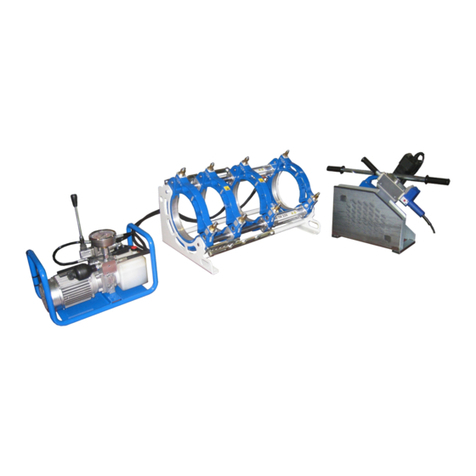
GF Piping Systems TOP 2.0 400 User manual

Instruction manual
GF Piping Systems
TOP 2.0 400/500/630
Butt Fusion Machine

All rights reserved, in particular the rights of duplication and distribution as well as
translation. Duplication and reproduction in any form (print, photocopy, microfilm or
electronic) require the written permission of Georg Fischer Omicron S.r.l..

Operating instructions TOP 2.0 400/500/630 Table of contents
I
Table of contents
Page
Table of contents I
1About this manual 1
1.1Warning notice 1
1.2Other symbols and notices 2
1.3Abbreviations 2
2Safety instructions 3
2.1Proper use 3
2.2General safety measures 3
2.3Working with safety in mind 4
2.4Disposal 5
3General 6
3.1Introduction 6
3.2Range of application 6
3.3Copyright 6
4oduct identification and description 8
4.1Product identification 8
4.2Product description 8
5Technical specifications 10
6Transport and assembly 12
6.1Packaging 12
6.2Sensitivity 12
6.3Intermediate storage 12
6.4Scope of delivery 12
7Fusion preparation 13
7.1General information 13
7.2Preparations 13
7.2.1Connection to the power supply 15
7.2.2Push buttons, LED of the operator interface 16
7.2.3Error Messages 17
7.2.4TOP 2.0 WeldinAir 18
7.2.5Heating element temperature adjustment 18
7.2.6Temperature offset adjustment 19
7.2.7Unit of measurement setting 19
7.2.8Timer adjustment 20
7.2.9Start Timer 20
8Fusion 21
8.1The basics of Butt Fusion 21
8.2The fusion process 22
8.2.1Calculating the drag pressure 22
8.2.2Preparing the fusion surfaces 22
8.2.3Calculating the fusion pressure 24
8.2.4 Adjusting the fusion pressure 24

Table of contents Operating instructions TOP 2.0 400/500/630
II
8.2.5Fusion process
25
8.2.6Automatic cooling pressure 28
8.3Visual check of welding bead 29
8.4Example TOP 500 29
9Failure analysis 31
10Maintenance 33
10.1Replacement of worn parts 33
10.2Hydraulic system 33
10.3Hydraulic unit 33
11Customer Service 36

Operating instructions TOP 2.0 400/500/630 1 About this manual
1
1 About this manual
This manual is valid for TOP 2.0 400, TOP 2.0 500 and TOP 2.0 630 butt-
fusion machines (hereinafter referred to as TOP 2.0 400/500/630).
The warning notices, symbols and their meanings as used in this
manual are explained below to help you quickly understand the
format of this instruction manual and how to use the machine safely.
1.1 Warning notice
Warning notices are used in this manual to inform you of possible
injuries or damage to property. Please read them and always abide
by these warnings!
Symbol Meaning
Danger
Imminent accute danger!
Failure to comply could result in death or extremely
serious injury.
Warning
Possible accute danger!
Failure to comply could result in serious injury.
Caution
Dangerous situation!
Failure to comply could lead to injury or damage to
property.

1 About this manual Operating instructions TOP 2.0 400/500/630
2
1.2 Other symbols and notices
Symbol Meaning
Attention Mandatory: you must observe this regulation
Advice
1.
►
Suggestion: this notice contains especially important
information
Action request in a sequence of actions
Stand-alone request for action
1.3 Abbreviations
Abbr. Meaning
TOP 2.0 400
TOP 2.0 500
TOP 2.0 630
Butt fusion machine d 125–400 mm
Butt fusion machine d 200–500 mm
Butt fusion machine d 315–630 mm
DVS Deutscher Verband für Schweisstechnik
(German Association of Fusion Technology)
PE Polyethylene
PP Polypropylene
PTFE Polytetrafluorethylene
d Pipe outer diameter

Operating instructions TOP 2.0 400/500/630 2 Safety instructions
3
2 Safety instructions
The TOP 2.0 400/500/630 Butt Fusion Machines are designed
according to the latest standards of technology. Using it for purposes
other than those described in this manual may cause injury to the
operator or to others. It may also cause damage to the machine or
other equipment.
Any person in the company, who is involved in the assembly,
disassembly, reassembly, installation, operation or maintenance
(inspection, maintenance work, repair work) of the TOP 2.0
400/500/630, must have read and understood the complete
instruction manual, and in particular Section 1 on “Safety instructions”.
It is recommended that the user has this confirmed in writing.
Thus:
The machine should only be used when in perfect working order.
Always follow the safety instructions.
Complete documentation should be kept in the vicinity of the
machine.
2.1 Proper use
The TOP 2.0 400/500/630 are to be used exclusively for the fusion of
pipes and fittings made of PE, PP. Any other use is not permitted.
2.2 General safety measures
Use only the materials and dimensions specified in this manual.
Other materials may only be used after consulting Georg Fischer
Omicron after-sales service.
Use only original Georg Fischer Omicron spare parts and
equipment.
Inspect the TOP 2.0 400/500/630 daily for visible signs of damage or
defects. Have damage or defects repaired immediately.
Any work on the electrical equipment may only be done by a
specialist.
Observe all the regulations, standards and guidelines applicable in
your country.

2 Safety instructions Operating instructions TOP 2.0 400/500/630
4
2.3 Working with safety in mind
“Make your contribution to safety in the workplace."
Report any deviations from normal operation immediately to the
person in charge.
Always keep safety in mind while working.
For your own personal safety as well as for the safe and optimal
handling of the machine, the TOP 2.0 400/500/630 must be installed
correctly.
Connect hydraulic hoses to and from the machine only when the
hydraulic unit is shut off and not under pressure (observe manometer).
Danger of electric shock!
Inspect the electrical cords and devices!
Do not connect damaged cords or devices to the power supply.
Danger of burning!
The heater is hot (220 °C)!
Danger of burning hands on the hot heater.
Do not touch the heater when on.
Danger of burning!
Use the handles on the heater.
To move the heater, use the gloves! (EN 407 321XXX)
Danger of crushing hands!
The machine slide moves!
Danger of injury to hands in the moving machine slide!
Do not reach inside the machine when moving to the end positions.
Danger
Warning
EN 407 321XXX
Warning

Operating instructions TOP 2.0 400/500/630 2 Safety instructions
5
Danger of cutting hands!
The planer blades are sharp!
Danger of cutting hands on the planer disk.
Do not touch the rotating planer disk.
Danger of injury due to high pressure oil leakages!
Inspect the outside wall of hydraulic hoses under pressure: make sure you
wear safety glasses before doing it!
Do not touch leaking oil with hands! Escaping high pressure oil can cause
skin penetration injuries!
Release the oil pressure to zero before replacing defective hoses.
Danger of bruising!
Machine components are heavy!
To move the components, use the gloves! (EN 388 2241)
2.4 Disposal
Shavings and used hydraulic oil should be disposed of properly.
Observe all the regulations, standards and guidelines applicable in
your country.
Separate collection of electronic and electrical waste (from the
equipment) has to be ensured through appropriate systems.
note:
The symbol below indicates separate collection for electrical and
electronic equipment according to 2002/96/CE WEEE directive
(Waste Electrical and Electronic Equipment).
Warning
Warning
EN 388 2241

3 General Operating instructions TOP 2.0 400/500/630
6
3 General
3.1 Introduction
This instruction manual was written for those persons responsible for
the operation and care of the TOP 2.0 400/500/630. It is expected and
assumed that such persons have read, understood and will abide by
the manual in its entirety.
Only with the knowledge contained in this manual can faults on the
TOP 2.0 400/500/630 be prevented and trouble-free operation be
ensured. It is therefore imperative that the responsible persons are
familiar with this manual.
We recommend that this manual be read carefully prior to putting the
machine into operation, as we are not liable for any damage or
interruptions in operation resulting from failure to comply with this
manual.
Should problems nevertheless arise, please contact Georg Fischer
Omicron s.r.l. directly or the nearest service representative.
This manual applies only to the TOP 2.0 400/500/630 butt-fusion
machines.
We reserve the right to make technical changes necessary to
improve the TOP 2.0 400/500/630 which may result in deviations from
the illustrations and information contained in this manual.
3.2 Range of application
The TOP 2.0 400/500/630 is designed exclusively for the fusion of
thermoplastic pipes, fittings and valves according to the specified
dimension range. Any other use is not authorized. The manufacturer
cannot be held liable for damages resulting from unauthorized use;
the user bears sole responsibility.
3.3 Copyright
The copyright for this instruction manual is held by Georg Fischer
Omicron S.r.l..
This instruction manual is intended for assembly, operation and
maintenance personnel. No part of the technical regulations or
illustrations contained herein may be reproduced or distributed in any
form, used illicitly for competitive purposes or passed on to others.

Operating instructions TOP 2.0 400/500/630 3 General
7
Georg Fischer Omicron S.r.l
Via E. Fermi, 12
I 35030 Caselle di Selvazzano
Padova (Italy)
Telephone +39 049 8971411
Fax +39 049 8971410

4 oduct identification and description Operating instructions TOP 2.0 400/500/630
8
4 oduct identification and
description
4.1 Product identification
In accordance with the directives for machines, an identification
label is attached to the base machine, showing the following
information:
1. Manufacture
r
2. Type of machine
3. Serial number
4. Piston area
5. Pipe range
6. Year of manufacture
7. Weight
8. Barcode
4.2 Product description
Base Machine
Hardened and hard chrome-
plated guide shafts (1)
Adjustable third clamp (2)
Pull-Off mechanism for heating
element (3)
Hydraulic unit (Control Panel)
Oil dipstick (1)
Pressure regulation valve,
equalization and fusion pressure
can be pre-set (2)
Operator interface (3)
1
3
2
3
1
2
6
4
8
5
3
7
21
7

Operating instructions TOP 2.0 400/500/630 4 oduct identification and description
9
2
1
3
Connectors for output signals to WR
200 / WR 200 S welding recorder
(optional):
o Pressure (4)
o Heating element temp. (5)
Socket for planer (6)
Socket for heating element (7)
Main switch (8)
Quick action couplings (9)
Mains plug (10)
Heating element
PTFE-coating
Power multi-cord (4 m) with
integrated temperature sensor probe
Thermometer integrated
Electric planer
Self-locking device against
accidental unhooking (1)
Planer blades sharpened on both
sides (2)
Safety micro switch against
accidental starting (3)
Storage Case
Zinc-coated steel case for transport
and storage of both heating element
and pipe planer
8
5 6 7
9
10
4

5 Technical specifications Operating instructions TOP 2.0 400/500/630
10
5 Technical specifications
TOP 2.0 400
TOP 2.0 500
TOP 2.0 630
Base
machine Total piston
area: 904 mm21413 mm21413 mm2
Facer Power: 1100 W
760 W (*) 1500 W
Voltage: 230 V
1 Phase (2 wires) 400 V
3 Phase (4 wires) 400 V
3 Phase (4 wires)
Heater Power: 3500 W
4000 W
8000 W
Voltage: 230 V
1 Phase (2 wires) 400 V
3 Phase (4 wires) 400 V
3 Phase (4 wires)
Hydraulic
unit
Power: 1500 W
1500 W
1500 W
Voltage: 400 V
3 Phase (4 wires) 400 V
3 Phase (4 wires)
Max pressure: 160 ba
r
200 ba
r
200 ba
r
Oil type Viscosity 46
2 liters of hydraulic oil in canister
Machine
complete
Power: 5,7 kW 6,3 kW
10,5 kW
Voltage: 400 V
±
10%
3 Phase (4 wires) 400 V
±
10%
3 Phase (4 wires) 400 V ± 10%
3 Phase (4 wires)
Noise level:
70 dBA
(*) : 1500 W with PP version
Attention:power generator output must satisfy the following connections
TOP 2.0 400
L1 - L2 = 400 Vac
L2 - L3 = 400 Vac
L1 - L3 = 400 Vac

Operating instructions TOP 2.0 400/500/630 5 Technical specifications
11
TOP 2.0 500-630
L1 - L2 = 400 Vac
L2 - L3 = 400 Vac
L1 - L3 = 400 Vac

6 Transport and assembly Operating instructions TOP 2.0 400/500/630
12
6 Transport and assembly
6.1 Packaging
A decisive factor in the choice of packaging is the means of
transport. Usually the machine and all the accessories are delivered in
a wooden case.
6.2 Sensitivity
Special care must be taken when transporting the machine in order
to prevent damage from impact or improper loading and unloading.
All movable parts must be fixed in place.
Transport insurance should be provided for according to the type and
duration of transport. Condensation due to large temperature
fluctuations and sharp jolts during shipment should be avoided.
Please handle the machine with care.
6.3 Intermediate storage
If the machine is not used immediately upon delivery, the machine
must be stored in a safe place and properly covered.
6.4 Scope of delivery
The contents (number of transport crates, pallets, packages) and their
condition should be checked immediately upon receipt. Any
damage and/or missing parts should be noted right away on the bill
of lading and reported to Georg Fischer Omicron S.r.l. without delay.

Operating instructions TOP 2.0 400/500/630 7 Fusion preparation
13
7 Fusion preparation
7.1 General information
The Fusion Process described in the following chapters is based on the
instruction sheets and guidelines issued by the DVS 2207.
The fusion area should be protected against the influences of
weather (humidity, ambient temperature <+ 5 °C, extreme direct
exposure to sun) with such measures as pre-warming the fusion
materials, tents or heating.
For optimal use of the TOP 2.0 400/500/630 the operating personnel
should be specially trained by Georg Fischer. In-depth knowledge of
the machine and it´s components and competence rule out handling
errors thereby also preventing faulty fusion joints.
7.2 Preparations
The standard configuration of the base machine is set to joint pipe to
pipe by using 2 clamps to fix each pipe in the base machine. The
planer and the heating element are inserted between the two central
clamps.
In order to clamp particular constructions or T-pieces or to use a
flange adapter, shift the clamping unit B to the required position. To
do this, rotate the two spacers C (upper and lower) from the original
position, position the clamping unit B and fix it with the two spacers C.
The pipe preparation and welding position is now changed, insert the
heating element into the pull-off mechanism between A and B.
Clean the couplings on the base machine and the hoses.
Connect the hydraulic hoses to the base machine and to the
hydraulic unit.
If the hydraulic hoses are not used, seal the couplings with the
protective caps. Clean the protective caps first.
Attention

7 Fusion preparation Operating instructions TOP 2.0 400/500/630
14
Replace the heater if the PTFE -coating is damaged. Failure to comply
could impair the quality of the fusion weld.
In order to weld pipes and/or fittings with an outer diameter smaller
than the clamp of the base machine, insert matching clamping half
shells and fasten them with the screws.
Clamp the components to be jointed in such a way that the
pipe/fitting ends reach out at least 30 mm from the clamps in
order to perform a proper weld. Make sure they are exactly
aligned in the axial direction.
If necessary, the components can be turned or the clamping force
changed to achieve a better clamping position.
Here below some recommendations in order to avoid damages to the
heating element when it is working in combination with the pulling off
mechanism:
Must be a gap here during the complete carriage stroke when moved
pipe is in contact with the heating plate.
Must be a gap here during the complete carriage stroke when the
steady pipe is in contact with the heating plate.
Gap must be 20 mm on both sides at final working position!
Warning

Operating instructions TOP 2.0 400/500/630 7 Fusion preparation
15
7.2.1 Connection to the power supply
1. Connect the planer and heating element to the hydraulic unit.
2. Connect the hydraulic unit to the power outlet or power
generator.
Check the voltage!
The generator has to be started before connecting the consumers and
must supply a constant output voltage!
Danger of electric shock!
Check the electrical cords and devices!
Do not connect damaged cords or devices to the power supply.
Connect all devices when the hydraulic unit is switched off to avoid
any damage!
3. After switching ON the hydraulic unit, the hydraulic unit shows the
actual temperature of the heater plate. The LED (1) is ON and
indicates the correct connection of the heating element. If the
temperature probe is damaged or the signal is interrupted or the
heating element is not connected properly, the display will show
the error “E40/E41”. In that case you have to disconnect the
power supply from the regulator and connect the heating
element.
4. To check the adjusted set temperature of the heating element,
press the button (3) or (4). The LED (2) will be lit when the set
temperature is being displayed.
5. By pressing buttons (3) and (5) simultaneously, the adjusted offset
of the heating element is displayed.
6. Check the temperature of the heater plate surface with a quick-
indication temperature measuring device according to the set
temperature.
Before beginning the first fusion, we recommend waiting approx. 10
minutes after the set fusion temperature has been reached to allow for
even heat distribution.
Caution
Danger
Attention
Advise

7 Fusion preparation Operating instructions TOP 2.0 400/500/630
16
7.2.2 Push buttons, LED of the operator interface
A The LED is permanently ON when the hydraulic unit is switched ON
and the display indicates the current heater plate temperature.
When flashing, the temperature is regulated at the set point.
B The LED is ON, when the set temperature is indicated on the
display.
C The LED is ON when the timer of the equalisation phase is
activated.
D The LED is ON when the timer of the cooling phase is activated.
E Push this button to adjust the two timer and to start the timer
1 Indication of system pressure
2 Indication of heater plate temperature and set point
3 Timer 2 and 5 / Set point timer
4 Push button to close the machine
5 Push button to release the system pressure
6 Push button to open the machine
7 Switch ON / OFF planer
8 Button to decrease values
9 Button to increase values
This manual suits for next models
2
Table of contents
Languages:
Other GF Piping Systems Welding System manuals
Popular Welding System manuals by other brands

EWM
EWM TIGSPEED OSCILLATION DRIVE 45 COLDWIRE operating instructions

EINHELL
EINHELL RT-EW 270 D operating instructions

SUNSTONE
SUNSTONE Orion 50p user manual

Lincoln Electric
Lincoln Electric INVERTEC 400TPX Operator's manual

ESAB
ESAB Caddy Arc 251i instruction manual

Lincoln Electric
Lincoln Electric Power Mig 215 XT Technical specifications