GFA KE 40.24-40,00 Ex User manual

f
Installation Instructions
ELEKTROMAT
KE 40.24-40,00 Ex
Model: 10002551 00001
-en-
Status: 26.03.2021

2
GfA ELEKTROMATEN GmbH & Co. KG
Wiesenstraße 81
D-40549 Düsseldorf
www.gfa-elektromaten.de

3
Table of contents
1General safety information .............................................................................................. 4
Safe operation ......................................................................................................................... 4
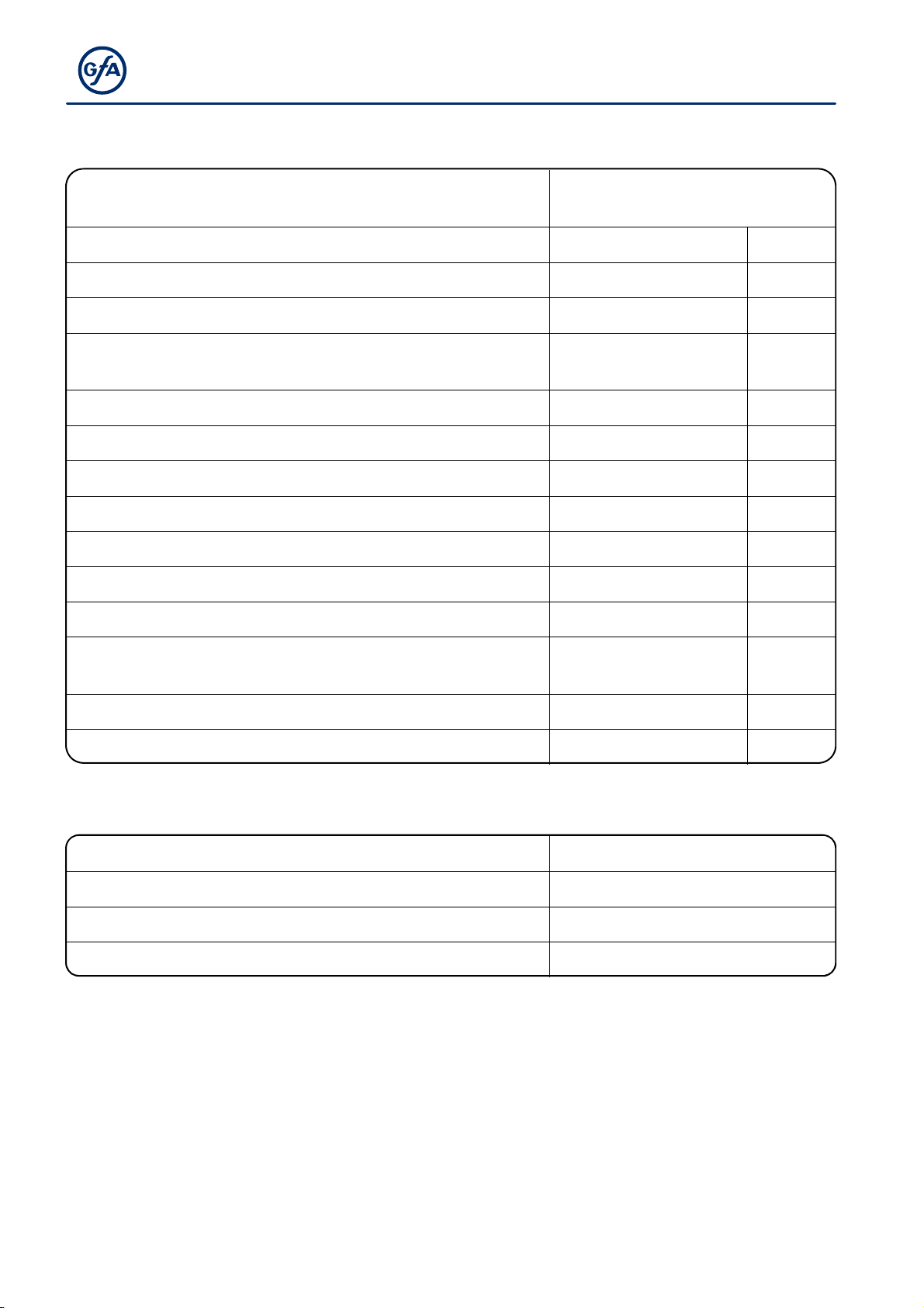
2Technical data of the drive unit ....................................................................................... 6
3Technical data of the gearbox ......................................................................................... 7
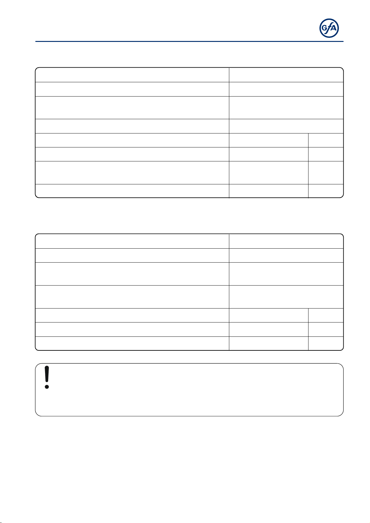
4Technical data of the motor ............................................................................................. 8
5Technical data of the terminal box ................................................................................... 9
6Technical data of limit switch / emergency manual operation switch ............................... 9
7Mechanical installation .................................................................................................. 10
8Electrical installation ..................................................................................................... 15
9Limit switch setting ........................................................................................................ 18
10Motor connection .......................................................................................................... 20
11Limit switch connection ................................................................................................. 20
12Emergency manual operation (emergency hand crank) ................................................ 21
13Completion of initial operation / inspection / operation ................................................... 23
14Declaration of conformity, Motor .................................................................................... 28
15Declaration of conformity, Accessories .......................................................................... 29
16Declaration of incorporation / Declaration of conformity ................................................. 31
Symbols
Warning - Potential injury or danger to life!
Warning - Danger to life from electric current!
Note - Important information!
▶ Requirement - Required action!
Schematic representations are based on product examples. Deviations from delivered
products are possible.

4
1General safety information
Specified use
The drive unit is intended for vertically moving doors. The force is transmitted using a
chain. Doors that must be secured against dropping require a separate safety brake. The
drive unit can be used in hazardous areas thanks to its explosion protection according to
ATEX 2014/34/EU.
The drive unit must be protected against moisture and aggressive environmental
conditions (such as corrosive substances). The drive units are only suitable for indoor use.
Appropriate protective measures must be taken for outdoor installation. The values
specified in the technical data of the drive unit must not be exceeded. The safe operation
can only be ensured if used as specified.
Target audience of these installation instructions
These installation instructions are geared towards qualified persons trained in the handling
of door systems. Expert knowledge, relevant skills and practical experience are what set
apart qualified persons. They are capable of safely carrying out the tasks involving
installation, maintenance and modernisation according to the instructions.
Safe operation
The safe operation of the product can only be ensured if it is used as specified. Follow the
installation instructions. Observe all specifications, especially warnings, when installing the
product in the overall system. GfA is not liable for damage resulting from non-observance
of the installation instructions. The resulting overall system must be reassessed for its
safety in accordance with applicable standards and directives (e.g. CE marking). These
installation instructions refer only to a part of the overall system and are not sufficient as
the sole instructions for the overall system. The installer of the system must prepare the
instructions for the overall system.
We recommend entering the danger area of the system only when the drive unit is at a
standstill.

5
Warning - Failure to follow these installation instructions may result in severe injury or death.
Please read these instructions before using the product.
Keep these instructions handy.
Include these instructions when passing on the product to third parties.
Warning - Danger from improper use of the product!
Do not let children operate the product unsupervised or use as a toy.
Warning - Danger to life from incorrect installation!
Work carried out improperly may result in death or severe injury from electrical
current or falling parts.
Allow only competent people to carry out the work.
Disconnect all cables from the power supply.
Observe valid regulations and standards.
Use suitable tools.

6
2Technical data of the drive unit
Explosion protection II 2G Ex db eb h IIC T4 Gb
II 2D Ex tb h IIIC 130°C Db
Output torque 400 Nm
Output speed 24 rpm
Output / hollow shaft 40,00 mm
Maximum output speed Open / Close
for frequency inverter operation 24 rpm
Supply voltage 3~ 400 V
Operating current 2,70 A
Operating frequency 50 Hz
Power factor cos φ 0,76
Maximum movements per hour 12 h-1
Manual force, emergency manual operation 246 N
Protection class IP 65
Limit switch range
(maximum revolutions of the output / hollow shaft) 20
Temperature range -20 / +40 °C
Installation height < 1000 m
Components used
Gearbox SG 85 60.T4
Motor F80-2GD CTVF /4
Terminal box 8146/1041
Limit switch / emergency manual operation switch 07-2511

7
3Technical data of the gearbox
Series SG 85-60.T4
Manufacturer GfA
Explosion protection II 2G Ex h IIC T4 Gb
II 2D Ex h IIIC 130°C Db
Max. output torque 400 Nm
Max. output speed 30 rpm
Shaft centre distance 85 mm
Transmission ratio 1:60
Temperature range -20 / +40 °C
Protection class IP 65

8
4Technical data of the motor
Type F80-2GD CTVF C4
Manufacturer ATAV (CEMP France)
Explosion protection II 2G Ex d IIC T4
II 2D IP65 T 125°C
Certificate of verification TUV IT 14ATEX021X
Supply voltage 230 / 400 +/- 10% V
Operating current 4.68 / 2.70 A
Operating frequency 50 Hz
Power 1.1 kW
Power factor cos φ 0.76
Motor speed 1430 rpm
Motor torque 7.3 Nm
Operating mode S1
Protection class IP 65
Temperature class T4
PTC resistors 20°/140° 100-250 / 1600-4000 Ω
IA / IN ratio 4.9
Braking torque of spring-loaded brake 8 Nm
Braking voltage 205 V DC
Operating current of spring-loaded brake 0.12 A
Rectifier type B2-DC 230/205
Temperature range -20 / + 40 °C

9
5Technical data of the terminal box
Type Ex e 8146/1041
Manufacturer Stahl
Explosion protection II 2G Ex e II T6
II 2D Ex tD A21 IP 66 T80°C
Certificate of verification PTB 01 ATEX 1016
Supply voltage 250 max. 1100 V
Terminal cross-section 2.5 mm2
Temperature range T6: -20 / +40
T5: -20 / +55 °C
Protection class IP 66
6Technical data of limit switch / emergency manual operation switch
Type 07-2511-113061G
Manufacturer Bartec
Explosion protection II 2G Ex d IIC T6
II 2D Ex tD A21 IP 66 T80°C
Certificate of verification EPS 14 ATEX 1766 X
Supply voltage 400 V
Temperature range -20 / +40 °C
Protection class IP 66
Attention – Damage to components!
The maximum allowable current applied to the limit switches is
2A 400V for AC-15 and 0.15 250V for DC-13.

10
7Mechanical installation
Warning – Explosion hazard!
Check the atmosphere for explosion hazards before commencing installation tasks.
Requirements
The permissible loads on walls, mountings, connection and transmission elements must not
be exceeded even for maximum holding or locking torque (▶ observe technical data).
Connection elements
▶ Use self-locking
connection elements with
a minimum strength of
800 N/mm2 (8.8).
▶ Use a screw that
precisely fits the hole.
▶ Use adequately
dimensioned washers for
elongated holes.
BAGAB00002_Z002 BAGAB00003_Z002
3 : 1

11
Permissible mounting positions
BAGAC03203_Z002
Transmission elements
▶ Correctly fit the sprocket. ▶ Correctly position the
sprockets.
▶ Correctly tension the
chain.
BAGAB00021_Z001
BAGAB00022_Z001

12
Mounting
4 boreholes are provided for mounting.
BAGAD03201_Z005

13
Installation
The following descriptions refer to a door which is not further defined. The door
manufacturer's specifications must also be observed.
Warning – Injury or danger to life possible!
Use a lifting device with sufficient load-carrying capacity for installation tasks.
▶ Completely grease the output shaft.
BAGAE01201_Z001
▶ Mount (①) and fixate (②) the sprocket. Do
not yet tighten. Mount the output shaft at
the right- or left-hand side (③) and fixate it
(④).
BAGAE03212_Z001

14
▶ Mount the drive unit. Do not yet tighten.
BAGAE03213_Z001
▶ Correctly position the sprocket (①). Mount
the chain (②). Fixate the sprocket (③).
BAGAE04214_Z001
▶ Correctly tension the chain (①/②). Tighten
all connection elements (M12) with 75 Nm
(③). Install all further connection elements
according to the specifications of the door
manufacturer.
BAGAE04215_Z001
175 Nm

15
8Electrical installation
Warning – Danger to life from electrical shock!
Disconnect the cables (mains OFF) and check that the supply is off
Observe the applicable regulations and standards
Ensure proper electrical connection
Use suitable tools
Carrying out the electrical installation
Remove the cover. Remove the cover.
Connect motor/limit switch connection cable

16
Protection against overload
Motor protection switch / motor protection relay mains operation
The "Ex" motor must be protected against overload by means of a motor protection switch or
a motor protection relay. Only use motor protection relays with manual reset. Short-circuit
protection is also required. Excess current must be set on the basis of the IA / IN ratio.
PTC resistor signal mains operation
The motor is equipped with installed temperature sensors (PTC) which can be used as
overload protection. This protection class is approved as the sole protection against overload
for flameproof motors "d"; it must be equipped with a separate evaluation unit. The evaluation
unit measures the temperature of the motor coil and deactivates the motor as soon as the
preset temperature is exceeded. This safety device can only be reset by hand. Short-circuit
protection is also required.
PTC resistor signal frequency inverter operation
Evaluation is similar to that in mains operation. The motors have an additional rating plate.
The features on the additional rating plate must be checked before initial operation of the
motor. The connecting cable of the temperature sensors (PTC) must be routed separately to
the motor cable.
Frequency inverter operation!
Shielded motor cables must be used.
Shielded cables require separate cable glands.
The brake requires a separate supply line.

17
Completing the electrical installation
Install cable entries and/or cable glands.
Flameproof enclosure!
The motor cable gland must ensure that the flameproof enclosure is closed.
In order to achieve the required tightness, the cable glands are equipped with different
sealing inserts. They are available for the following cable diameters:
5.5 – 8.0; 8.0 - 10.5 and 10. – 13 mm.
Sealing insert and cable diameter must be aligned. Cable glands are only suited for lines with
a smooth surface.

18
9Limit switch setting
The limit switch setting defines the final limit positions OPEN and CLOSE.
Requirement
The door should open by pressing the OPEN
push-button of the control. If the door closes,
L1 and L2 must be swapped in a de-
energised state.
Setting of OPEN final limit position
Open to the desired OPEN final limit position
using the OPEN push-button.
Turn the cam of the S3 OPEN limit switch to
the centre of the switch plunger ①.
Tighten the screw of the cam ②.

19
Check the door position:
Close the door ① until the cam is released
and open it again ② until the OPEN final limit
position is reached.
The OPEN final limit position can be
corrected by following the fine adjustment
procedure. Check the door position after each
correction.
The S1 EMERGENCY OPEN limit switch is preset by the setting of the OPEN final limit
position. The door must stop without posing any risks should the rotating direction be
incorrect or should there be a fault with the S3 OPEN limit switch. Follow the fine adjustment
procedure to correct the switching point of the limit switch as needed.
Setting of CLOSE final limit position and auxiliary limit switch
The same setting procedure applies as for setting the OPEN final limit position.

20
10 Motor connection
G1 Bridge rectifier
DC-side switching
M1 Motor
R1 PTC thermistor
R2 PTC thermistor
R3 PTC thermistor
Y1 Spring applied brake
11 Limit switch connection
S10 Emergency manual operation
X12 Terminal strip
S1 Emergency OPEN limit switch
S2 Emergency CLOSE limit switch
S3 OPEN limit switch
S4 CLOSE limit switch
S5
A
dditional limit switch
S6
A
dditional limit switch
This manual suits for next models
1
Table of contents
Other GFA Garage Door Opener manuals