Ghost Acoustic/MIDI system User manual

Acoustic MIDI System
Be the band.
User Guide

INTRODUCTION
Modular components
Saddle Pickups
Pagoda Shim
Hexpander
Traction Switch
Program Up/Down Switch *optional*
Tone Control
1/4” Jack and 9v Battery Connector
INSTALLATION
Locating ghost® Components
Tools Required
Do not file saddles!
Saddle Pickups & Pagoda Shim
Putting plugs onto pickup wires
Installing Hexpander & 13-pin jack
Mounting the Tone Control
Variable Control Layouts
Control Knobs
Wiring Connections Diagram
TECHNICAL DETAILS
Component Dimensions
Mounting hole diameters
Part Numbers

The ghost Acoustic/MIDI system lets you add MIDI
capability to almost any acoustic guitar, as well
as amplify the instrument’s natural sound with-
out the feedback problems of microphones or the
string choice restrictions of magnetic pickups.
The ghost saddle pickups turn the vibrations of the
strings into electrical signals that drive both of the ghost
Acoustic/MIDI modules: the Hexpander MIDI inter-
face, and the Tone Control adjustable acoustic preamp.
The ghost Acoustic/MIDI system was developed
for Carvin’s highly popular NS-1 chambered solid
body acoustic guitar, and now is available for
use in other applications. It is suitable for both
nylon-string and steel-string acoustic guitars.
INTRODUCTION

Modular Components
The ghost Acoustic/MIDI systems installs without
any soldering. The pickups, modules, switches, and
jacks plug into each other with small, computer-
style connectors. This makes the system easy to
install, and allows you to configure it to your needs.
J27
J26
J25
J24
J22
2

Saddle Pickups
Acoustic/MIDI saddles sets are available with two notch
sizes, for either steel-string or nylon-string guitars. The
dimensions and installation procedures are the same.
Both types of saddles fit in an 1/8”(3.2mm) saddle
slot, and are slightly oversized to permit sand-
ing to a snug fit. The plastic connectors are not
attached when you receive the pickups, so that
you can pass the wire through a 7/64” hole in
the bridge, and attach the connector afterwards.
dimensions: 0.130”(3.3mm) thick, 0.385”(9.8mm)
wide, and 0.236”(6.0mm) high.
standard wire length: 9”(230mm)
Modular Components
3

Pagoda Shim
The Pagoda Shim goes in the saddle slot and pro-
vides six “steps” at different heights for the saddles
to sit on, resulting in an 18” radius. For guitars with
flat fingerboards, the Pagoda Shim is not used.
4
The stepped roofs
of a pagoda

Hexpander
The Hexpander is the MIDI interface board
with integrated 13-pin connector. It interfaces
with most pitch-to-MIDI converters, and is de-
signed to be installed with the Tone Control
TraktionTM Switch
The TraktionTM Switch selects between two output
curves to optimize tracking for your converter and
playing style.
The TraktionTM
switch is located
in the slot below
the 13-pin jack,
and slides left for
Roland, and right
for Axon. For converters by other manufacturers,
try both settings and use the one that tracks best.
5

Tone Control
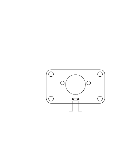
The OEM Tone Control is an adjustable acoustic
preamp that delivers true acoustic sound from
piezo pickups. The middle pot is wire mounted
so you can create custom control layouts. It is
designed to be installed with the Hexpander.
1/4” Output Jack & 9v Connector
The Acoustic/MIDI system includes a plug-in wir-
ing harness with the 1⁄4” output jack and a
9v battery connector. A metal battery holder
with self-adhesive backing is also provided.
Program Up/Down Switch *optional*
The program selector QuickSwitch scrolls up or down
through the MIDI patches. Modular plug connects
to the Hexpander or Tone Control bus bar without
soldering. The Up/Down Switch is optional, and
omitting it doesn’t require any jumpers in its place.
6

INSTALLATION
Installing the ghost Acoustic/MIDI system requires
some permanent modification of the instrument,
including holes through the sound board for the
pickup wires and preamp controls, and a hole in
the side for the 13-pin jack. If you’re uncomfortable
with any of the steps in this manual, please find a
qualified guitar technician to do the work for you.
7

Locating ghost Components
Adding the ghost® system to your instrument
begins with careful planning. Begin by plug-
ging the components into each other and lay
them out on top of the guitar to decide the loca-
tion of each component. Choose locations that are
convenient for you, and look for space conflicts
with structural parts on the inside of the guitar.
Make sure that the harness wires are long enough
to reach the location of each component. Re-
member that any of the optional controls can be
added to the system later if you’ve left space for
it, but drilling a hole in the wrong place can be
hard to hide. Some routing may be required to fit
the components in your particular instrument.
8

Tools Required
9
Electric drill and bits: 5/16” (12” long recommend-
ed), 9/32”, 1/4”, 7/64”, 1/16”
Square file for 13-pin jack hole
Phillips screw driver for mounting 13-pin jack
X-Acto knife
masking tape

Do not file ghost saddles!
Do not adjust the height of the strings by fil-
ing the string slots. This will alter the relation-
ship between the string and the encapsulated
pickup, and change the output unpredictably.
If you need to adjust the height of an individual string,
either carefully file the Pagoda Shim, or file the bottom
of the saddle, being careful not to damage the wire.
The saddles can be sanded to adjust the thickness to fit
a 1/8” (3.2mm) saddle slot, and the width can be filed
or sanded to accommodate narrower string spacings.
10

Saddle Pickups & Pagoda Shim
For guitars with flat fingerboards, such as clas-
sical guitars, the Pagoda Shim is not used. The
saddle pickups sit on the bottom of the saddle slot.
The saddles pickups fit in a 1/8” (3.2mm) saddle slot.
They are slightly oversized to permit sanding to a
snug fit. Each saddle is marked with a dot to orient the
pickup properly. This dot must face towards the fret-
board so that the pickup senses the string optimally.
11

Putting plugs onto pickup wires
Once the pickup wires have been threaded through the
7/64” holes in the bottom of the 1/8” saddle slot, the
metal crimps on the ends of the pickup wires can be
inserted into the plastic housing without tools. Align
12
For steel-string guitars and other guitars with ra-
diused fingerboards, the Pagoda Shim lies in the
bottom of the saddle slot, and the pickup saddles
sit on top of it. You may need to rout your saddle
slot deeper to accommodate the pagoda shim.
The pickup saddles should not protrude more
than 1/3 of their height out of the saddle slot.
It is possible to sand the Pagoda Shim thinner, but it is very
delicate, so if you choose to do this, proceed very carefully.

the crimps so that the catches on the plastic housing
will engage the crimps when they are fully inserted.
If you need to remove the housing, care-
fully lift both catches at the same time us-
ing an X-acto knife with a prying motion,
and withdraw both crimps at the same time.
13

Installing Hexpander & 13-pin jack
For instruments with solid-wood sides, reinforce the
area where you are going to cut the hole for the 13-pin
jack by gluing a small piece of 3/32” aircraft plywood
inside the guitar. This reinforcement protects against
cracking the wood, and makes the 13-pin jack stron-
ger in case you step on your cable. Aircraft plywood is
available at most hobby shops, and can be stuck on us-
ing regular wood glue (white) or carpenter’s glue (yel-
low). Allow 24 hours to dry before cutting or drilling.
For mounting the Hexpander output on the edge
of the instrument, the integral 13-pin jack requires
If your body depth is large enough, mount the 13-
pin jack plate with the long dimension across the
depth of the side. This will make for a stronger mount
by placing the mounting holes closer to the kerf-
ing. Also, the plate will require less curvature to fit.
14

a rectangular mounting hole in the body. Choose
a location for this hole, checking that there is room
for the Hexpander behind it, and that the ribbon
cable will reach from here to the Tone Control Module.
15
13-pin Jack Template
The size and placement of this hole can be determined
using the full-size template on the following page.
This space intentionally left blank
for reverse of template

13-pin Jack Template
Cut out this full-sized template and use it to
mark the location of the holes to drill for mount-
ing the 13-pin jack on the edge of your guitar.
16

Tape the template to the edge of the instrument, and
mark the center of the circles onto the guitar by tap-
ping through the template into the lacquer using a
center punch and a small hammer. Using an X-Acto
knife, slice through the template along the edges of
the inner rectangle, etching lines in the lacquer to
mark the edges of the mounting hole. Remove the
template and make sure these lines connect in the
corners (this prevents your lacquer from chipping
beyond the scratched lines when you begin drilling).
17

Using a 1/16” bit, drill the four holes for the mount-
ing screws in the outer most marks to a depth of
1/4”. Make these holes perpendicular to the sur-
face. Using the 7/64” bit, drill the inner four marks,
defining the four corners of the mounting hole.
18
Table of contents
Popular Speakers System manuals by other brands

Sven
Sven MS-900 Operation manual

Wharfedale Pro
Wharfedale Pro KH series User instruction manual

HH Electronics
HH Electronics Vector VRC-210 user manual

Creative
Creative T4 Wireless MF0430 Signature Series quick start guide

promethean
promethean ActivSound 75 manual

Sony
Sony HT-CT380 operating instructions