Gifas-electric TrafficLED User manual

TrafficLED / CircLED
Seite 1 / 22
Created
15.06.2015
chal
Modified
04.10.2017
roen
Object-ID
989827
TrafficLED / CircLED
Installation instructions
VERSION
MODIFICATIONS
1.0
First edition
1.1
Editorial changes
1.2
Supplement - installation with pipe laying and levelling console

TrafficLED / CircLED
Seite 2 / 22
Created
15.06.2015
chal
Modified
04.10.2017
roen
Object-ID
989827
Table of contents
General information................................................................................................................3
1.1 Marking concept for hazards and hints............................................................................3
1.2 Responsibilities of the operator........................................................................................3
Introduction ............................................................................................................................4
2.1 Installation conditions TrafficLED / CircLED....................................................................4
2.2 TrafficLED.......................................................................................................................5
2.3 CircLED...........................................................................................................................5
Installation instructions TrafficLED ......................................................................................6
3.1 Installation into existing ground covering (directly with system cable)..............................6
3.2 Installation with pipe laying............................................................................................10
3.2.1 Variants in existing ground covering...................................................................10
3.2.2 Variant on foundation ground.............................................................................11
3.2.3 Cabling...............................................................................................................12
Installation conditions Traffic-/CircLED with leveling support..........................................13
4.1 Selecting the levelling range..........................................................................................13
4.2 Installation instructions for the levelling console ............................................................14
Removing the TrafficLED top ..............................................................................................20
5.1 Procedure when removing.............................................................................................20
Service ..................................................................................................................................22
6.1 Service addresses.........................................................................................................22
6.2 Imprint...........................................................................................................................22

TrafficLED / CircLED
Seite 3 / 22
Created
15.06.2015
chal
Modified
04.10.2017
roen
Object-ID
989827
General information
1.1 Marking concept for hazards and hints
Hazard
Hazardous situation which will cause serious injury or even death if it is not prevented.
Caution
Hazardous situation which could cause slight to moderate injury if it is not prevented.
Hint
Indicates information which does not concern personal injury, e.g. hints in respect of material damage.
Protective measures
Increase safety by applying a protective measure.
1.2 Responsibilities of the operator
-Make sure that this document is always kept in a safe place in a legible form together with the unit.
-Read these instructions carefully before first start-up of the unit.
-This product has been developed and produced exclusively for the use indicated in these documents.
Every other use, which is not mentioned explicitly, could affect the intactness of the product and/or
could constitute a source of danger.
-The manufacturer rejects any liability for damage which has been caused by incorrect or non-intended
use of the product.
-In countries, which do not belong to the European Community, the national legal reference regulations
as well as the standards and regulations applicable in these countries have to be observed for warranty
of a corresponding safety level.
-The installation has to be carried out according to the applicable regulations.
-The manufacturer shall assume no liability for inexpert execution of installation as well as deformations
which may occur during operation.
-The electric power supply shall have to be switched off before executing any action on the plant.
-Original parts of the manufacturer shall be used exclusively during maintenance. Maintenance work
may be carried out by qualified staff only.
-All procedures which are not explicitly mentioned by the manufacturer in the instructions are not per-
mitted.
-The packing material must not be stored within the reach of children as it could be a potential source
of danger.

TrafficLED / CircLED
Seite 4 / 22
Created
15.06.2015
chal
Modified
04.10.2017
roen
Object-ID
989827
Introduction
To ensure proper installation, the following steps and notes must be complied with under all circum- stances.
Only this way can it be ensured that the product will work to complete satisfaction.
Read all instructions before starting installation. Our sales department will be happy to answer any
questions you may have.
Hint
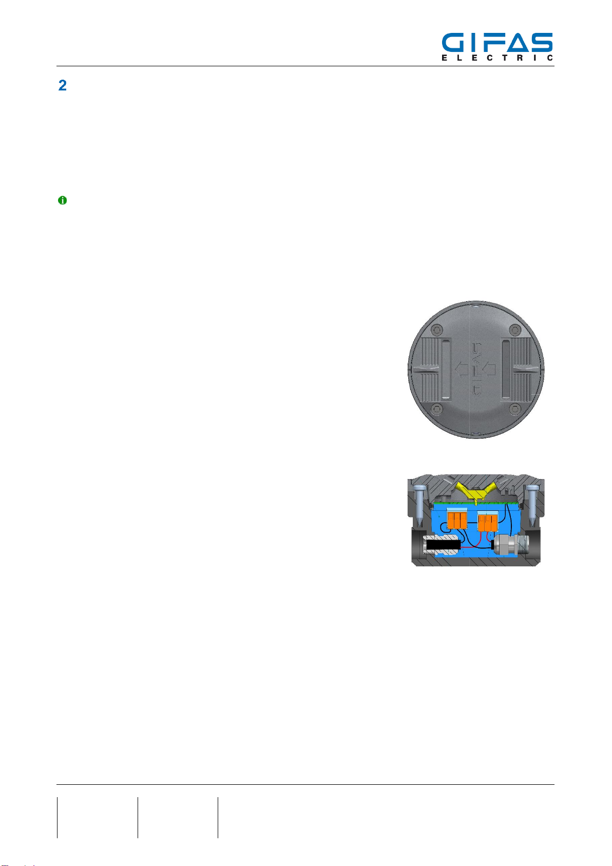
The content of the installation instructions predominantly refers to TrafficLED, but is also valid for CircLED as
well. This applies for pictures correspondingly and is valid for both applications. TrafficLED is fitted with a metal
ring for the alignment of the plastic mounting socket. This is not used in the CircLED. There are two different
installation gauges for TrafficLED and CircLED. It is imperative that the corresponding installation gauges are
used for installation. Without the correct installation gauge, the lights cannot be fitted flush with the roadway.
2.1 Installation conditions TrafficLED / CircLED
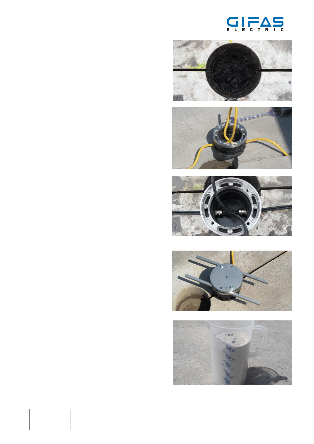
-The road surface must have the necessary depth and stability so
that the TrafficLED can withstand the traffic load.
-The mounting socket must be installed firmly in the roadway. If the
asphalt moves, the socket may have to be placed again.
-The surface around the light must be flat; the socket installed must
not protrude. The upper part of TrafficLED only protrudes 4 mm
(CircLED 3.5 mm) above the roadway.
-In order to increase the service life, the lights should be installed
between or next to the lanes.
-In order to increase the service life, the lights should be installed
between or next to the lanes.
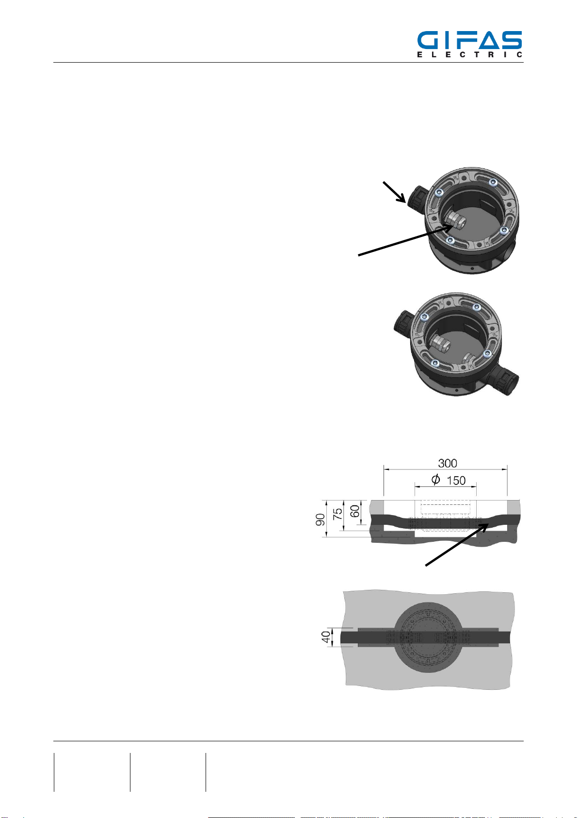
-Only use mortar which withstands the load correspondingly. Note
in the process that small cracks may occur between surface and
TrafficLED / CircLED.
-In order to comply with the necessary operating voltage, the cable
cross-section must be adjusted to the cable length.
-Install only in dry weather or under a covered installation site.
-Installation work must not be carried out at roadway temperatures
of below 5°C or above 30°C as well as in wet conditions / rainfall.
The drying time of mortar may take several hours in case of low temperatures!
-TrafficLED has been designed in such a way that it can be mounted opposite to the driving direction
as well.

TrafficLED / CircLED
Seite 5 / 22
Created
15.06.2015
chal
Modified
04.10.2017
roen
Object-ID
989827
Gauge TrafficLED
(Item no. 143015)
Gauge CircLED
(Item no. 174536)
2.2 TrafficLED
2.3 CircLED

TrafficLED / CircLED
Seite 6 / 22
Created
15.06.2015
chal
Modified
04.10.2017
roen
Object-ID
989827
Installation instructions TrafficLED
3.1 Installation into existing ground covering (directly with system cable)
Mark holes and groove
Measure and mark the centres of the holes; mark the path
of the groove through the centres of the holes with a chalk
line.
Hint
If at all possible, mill the groove only at a 0° or 90° angle
to the light beam so that the light no longer needs to be
aligned.
Mill the nut for hot pouring
Use a groove miller with the appropriate diameter. For
short distances, mill the groove and check the width and
depth, correcting if necessary. Finish milling the groove.
Depth: 60mm (± 5mm)
Width: 11mm for round cables of diameter
Ø 8.6mm,
Item no. 036352
6mm for system cable with width of
5.25mm, Item no. 115788
For 11mm clamping profile
Use a groove miller with an 11mm (± 1mm) milling blade;
adjust the depth to 60mm (± 5mm). For short distances,
mill the groove and check the width and depth, correcting
if necessary. Finish milling the groove.
The clamping profile is not suitable for permanent drive
over!
Drill the tap holes:
Drill a tap hole with a diameter of 150mm (+5/-0mm) and
a depth of 90mm (+5/-0mm).
Remove drilling core and check the depth of the hole
CircLED
TrafficLED

TrafficLED / CircLED
Seite 7 / 22
Created
15.06.2015
chal
Modified
04.10.2017
roen
Object-ID
989827
Clean the groove and holes
Remove all drilling mud, dirt and dust from the groove and
holes. Rinse / blow out the groove and holes.
Insert the cables
Place the installation boxes next to the holes. Lay the ca-
ble next to the groove and thread it through the installation
boxes.
Lay the cable in the groove and the installation boxes in
the holes. Pull the cable loops until the cable is fully in-
serted into the groove.
Tighten the threaded cable glands
Thread the cable into the installation box as shown in the
picture: loop length at least 30cm. Tighten the threaded
cable glands with a spanner (SW17).
Place the installation guide
Remove the installation box from the hole.
Place the installation guide on the installation box so that
the two square rods point in the direction of the light
beam.
Use 2 screws to screw the installation guide onto the in-
stallation box with the pre-fastened alignment ring.
Mix the mortar
The mortar must bemixed andprocessed according to the spec-
ifications of the mortar producer.

TrafficLED / CircLED
Seite 8 / 22
Created
15.06.2015
chal
Modified
04.10.2017
roen
Object-ID
989827
Fill in the mortar
Fill the mortar into the hole up to 6cm below the road sur-
face; wet the hole wall up to the top with mortar.
Hint
Mortar sets very quickly, especially at higher tempera-
tures.
Installation box must be positioned immediately.
Installation the box, step 1
Place the installation box, together with the installation
guide, on the mortar in the hole and fully insert the cable
into the groove.
If the cable inlet permits, align the square rods of the in-
stallation guide precisely in the desired direction of light
emission and insert them into the mortar until they rest
flush on the road.
Hint
If necessary, apply weight to the cemented box to ensure
level installation
Check the alignment
After the mortar has dried, unscrew the installation guide
and check whether the installation orientation is correct.
If the alignment is not at a 0° or 90° angle, loosen the
alignment ring on the installation box, turn it to the desired
position and re-tighten it.
The TrafficLED can also be aligned later, but the align-
ment tool must be used then.
Mortar
Foundation
Road surface

TrafficLED / CircLED
Seite 9 / 22
Created
15.06.2015
chal
Modified
04.10.2017
roen
Object-ID
989827
Installing the box, step 2
Insert the supplied blank plastic cover.
If necessary, temporarily cover the groove so the mortar
cannot flow away.
Add mortar again and fully cement in the installation box.
Seal the groove
with a glass fibre cord and hot pouring:
Place the glass fibre cord in dust-free and dry groove,
and fill in with hot bitumen flush to the surface.
for 11mm clamping profile:
Place the clamping profile into the dust-free and dry
groove flush to the surface.
The clamping profile is suitable for permanent drive over!
Preparing the installation box connections
Once the mortar has fully hardened, clean the edge of the
installation box and the immediate surroundings; then re-
move the blank cover.
Hint
To ensure level, sealed installation, the bearing surfaces
of the TrafficLED top must be absolutely clean.
The installation box must be completely dry inside

TrafficLED / CircLED
Seite 10 / 22
Created
15.06.2015
chal
Modified
04.10.2017
roen
Object-ID
989827
3.2 Installation with pipe laying
The installation socket with pipe connecting nipple and cable screw is used in the system variant with pipe
laying. The pipe is connected tightly to the pipe by means of the pipe screw connection. The inner cable screw
stops water from entering the entire system in case of pipe damage of a damaged light.
Article
-Item no. 167067 With single pipe connection
(TrafficLED)
-Item no. 167065 with double pipe connection
(TrafficLED)
3.2.1 Variants in existing ground covering
Drilling core hole
Drill core hole with a diameter of 150 mm (+5 / 0 mm)
and a depth of 90 mm (+5 / 0 mm). Break out drill hole
and check depth.
Milling groove
Use a grooving cutter with the corresponding diameter.
Mill a groove for a short distance, and check width and
depth. Correct, if need be. Finish milling the groove.
Depth: 60mm (± 5mm)
Width: approx. 20 mm for corrugated tube,
diam. 21.1 mm
M25 conduit gland for hose
21.2mm
Item no. 128266
M16 cable gland
flexible conduit (AD = 21.1)

TrafficLED / CircLED
Seite 11 / 22
Created
15.06.2015
chal
Modified
04.10.2017
roen
Object-ID
989827
Cleaning groove and boreholes
Widen groove to 30 mm for pipe connection at the drill
hole. Completely remove drilling mud, dirt and dust from
the groove and drill holes. Flush / blow out the groove
and drill hole.
Laying pipe / placing installation socket
Lay the corrugated tube, diam. 21.2 mm, into the
groove; pass pipe through pipe connection nipple. Use
the installation gauge to position and align TrafficLED.
Use mortar to cement the installation socket and corru-
gated tube.
3.2.2 Variant on foundation ground
Preliminary work / laying pipe
Leave out position of installation socket
(approx. 300 x 150 x 90 mm).
Lay corrugated tube (diam. 21.2 mm) on the founda-
tion ground; partially attach, and pull through opening.
Caution! When the pipe has to be covered with as-
phalt, the pipe has to be protected against heat.
Outer coating / underlay
The outer coating is prepared.
When the outer coating is hard, the opening has to be
cleared, and this area has to be removed from dirt and
dust.
Road surface
Fondation
Sheeting / block out
Mörtel
flexible conduit (AD=21.1)

TrafficLED / CircLED
Seite 12 / 22
Created
15.06.2015
chal
Modified
04.10.2017
roen
Object-ID
989827
Place installation socket
Pass the corrugated tube into the pipe connection nip-
ple.
Use installation gauge to position and align the Traf-
ficLED.
Cement the installation socket with mortar.
Hint
The length of the installation gauge may be too short
and must be applied crosswise.
3.2.3 Cabling
Pull the cable into the corrugated tube, and fit a loop for the connection in the ground box.
mortar
mortar

TrafficLED / CircLED
Seite 13 / 22
Created
15.06.2015
chal
Modified
04.10.2017
roen
Object-ID
989827
Installation conditions Traffic-/CircLED with leveling support
4.1 Selecting the levelling range
-The levelling console can be used for 2 different height adjustment ranges.
Adjustment range:
-TrafficLED 85-113mm
-CircLED 74-102 mm
Place the retaining plate, with the brackets facing up,
on the black marking light base.
Adjustment range:
-TrafficLED 113-168mm
-CircLED 102-157mm
Place the retaining plate, with the brackets facing down,
on the black marking light base.
Ring of CircLED not present

TrafficLED / CircLED
Seite 14 / 22
Created
15.06.2015
chal
Modified
04.10.2017
roen
Object-ID
989827
4.2 Installation instructions for the levelling console
Using four 4x12 mm chipboard screws, screw the
installation box onto the retaining plate from below.
Insert the 3 levelling nuts into the slots of the retaining
plate brackets and position them over the base plate us-
ing the 3 threaded rods.
Screw the 3 levelling nuts uniformly onto the threaded
rods.
Place the spacer plate and pipe clamps on the
retaining plate and lightly screw in two M4x12mm
screws by hand.
Do this on both sides in the case of continuous wiring.
Distance plate
connection
screw
fixing clamp
mounting plate

TrafficLED / CircLED
Seite 15 / 22
Created
15.06.2015
chal
Modified
04.10.2017
roen
Object-ID
989827
Mark the levelling console and position it at the intended
installation location.
Hint
We recommend that the TrafficLED base always be in-
stalled before laying any steel reinforcement.
Mark the attachment points and drill appropriate
mounting holes for the dowels.
Fasten the levelling console
Screw the console onto the surface using 4 screws
(max. screw diameter = 6.0mm).
(In the picture, additional spacers had to be attached
in order to reach the level of the road.)
Level the installation box
Adjust the 3 levelling nuts uniformly until the upper
edge of the alignment ring is precisely at the level
of the finished ground/road surface.
(the mounting bracket shown on the image is not con-
tained in the scope of delivery).

TrafficLED / CircLED
Seite 16 / 22
Created
15.06.2015
chal
Modified
04.10.2017
roen
Object-ID
989827
Cementing the installation box, 1st step
Hint
We recommend that the empty pipe is installed after lay-
ing the steel reinforcement.
Attach the installation pipes
Insert M25 pipes completely in the side hole on the
marking lamp base and tighten the clamps.
Hint
We recommend than a steel wire be pulled into the
empty pipe before cementing the coating.
Thus, the cables can be pulled in easily without prob-
lems.
Connect the base boxes with the installation pipes
according to the plan.
Ensure that the pipes are securely attached and are
not bent.
Aligning the TrafficLED light beam
The installation box is preassembled in such a way that
the light emission can be selected precisely at a 0° or
90° angle to the cable inlet.
Hint
The CircLED cannot be adjusted subsequently. It can
be moved by 90˚only. Before installation it is imperative
to watch the correct alignment.
Direction of travel

TrafficLED / CircLED
Seite 17 / 22
Created
15.06.2015
chal
Modified
04.10.2017
roen
Object-ID
989827
Alignment procedure
Hint
Loosen the 4 screws of the alignment ring on the in-
stallation box only slightly!
Place the alignment guide (fit the screw heads into the
slots) and turn the alignment ring into the desired posi-
tion.
Remove the guide carefully and tighten the 4 screws.
Preparing the cables/strands
Pull the cable loop from the installation box and cut it
so that 2 pieces of cable of about 15cm remain. Strip
the cable up to about 5cm from the threaded cable
gland.

TrafficLED / CircLED
Seite 18 / 22
Created
15.06.2015
chal
Modified
04.10.2017
roen
Object-ID
989827
Strip 11mm of the cables and TrafficLED wires. Push
into the terminals and close orange flaps.
Clean and drythe inside of the bottom box. Ensure that
the O-ring seal in the TrafficLED top is properly fitted.
Hint
Perform a funtional check before sealing the installa-
tion box.
For additional safety, fill the instgallation box with 2-
component silicone gel (e.g. BlueGel).
The two sealing gel components are thoroughly mixed
in the ratio 50/50. The installation box is then filled with
approx. 150 ml and has to be closed in liquid condi-
tions.
Install the TrafficLED top
Grease the o-ring seal and screws with waterproof, du-
rable lubricant before inserting the top part. Place the
top part of the TrafficLED on the adjustment ring and
press into the installation box.
Hazard
Do not pinch the strands anywhere.
Hint
The TrafficLED can generally be placed in 4 directions
(90° apart) on the alignment ring of the bottom box.
The arrow on the TrafficLED top should point in the di-
rection of travel. However, it has no further signifi-
cance.
Slightly tighten the TrafficLED (7Nm)

TrafficLED / CircLED
Seite 19 / 22
Created
15.06.2015
chal
Modified
04.10.2017
roen
Object-ID
989827
TrafficLED
CircLED
Before setting, the screws have to be greased with a
watertight durable lubricant.
First, slightly tighten all four cover screws uniformly
and crosswise; then tighten them with a torque of 7Nm.
Finished!

TrafficLED / CircLED
Seite 20 / 22
Created
15.06.2015
chal
Modified
04.10.2017
roen
Object-ID
989827
Removing the TrafficLED top
5.1 Procedure when removing
Uniformly and completely loosen the 4 screws.
Remove the 4 screws.
Uniformly pry out the top using the two slots.
This manual suits for next models
1
Table of contents
Popular Control Unit manuals by other brands

Brizo
Brizo MultiChoice VETTIS T60088 Installation instructions and owner's manual

TANDBERG
TANDBERG Codian MCU MSE 8420 Getting started guide

Egcon
Egcon GCU DG4 user manual

APEX DYNAMICS
APEX DYNAMICS A Series user manual

BENDIX
BENDIX SR-5 TRAILER SPRING BRK VALVE manual

Victron energy
Victron energy VE.Bus BMS V2 product manual