6 - INSTRUCTIONS FOR USE
0878_GB_99 - ELECTRIC OVEN
9· 16
01/2012
The countdown starts again by pressing button 8.
When the time counting is on pause the value can be modified by
operating on buttons 9 (increasing) and 10 (decreasing). To restart
the countdown press on button 8.
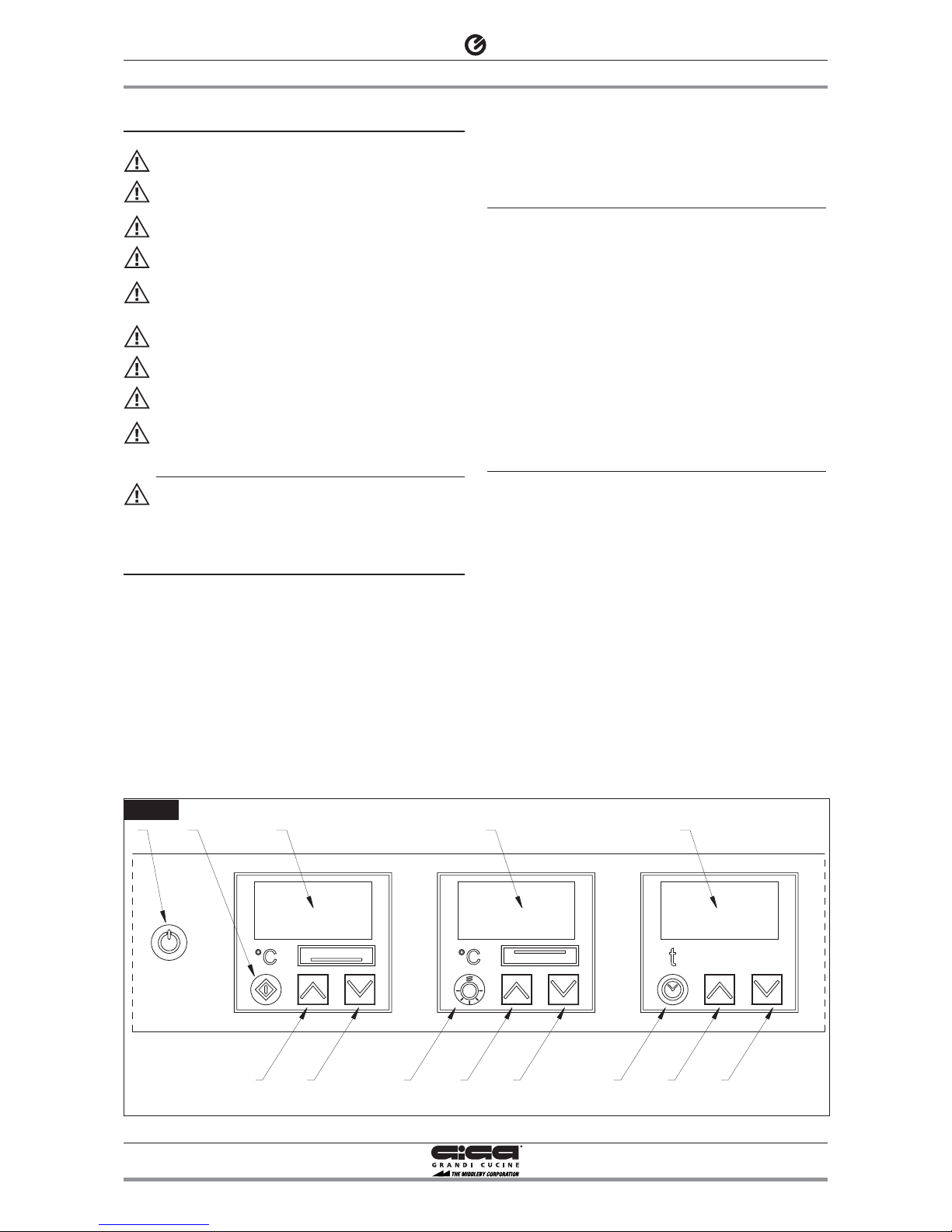
6.2.3 Interior light
Switch on the oven (see chapter 6.2 “Start-up and shutting down”).
To switch on the interior Light, press button 5.
6.3 Appliance care and frequency of mainte-
nance
6.3.1 Precautions in the event of a malfunction
If any malfunctions occur while the oven is in use, switch off imme-
diately and disconnect all power supplies. Call technical support.
6.3.2 Precautions if not using for long periods
If not using for long periods, clean the appliance thoroughly and
remove any residues, then dry perfectly. We recommend leaving the
door slightly open to allow air to circulate inside the oven and pre-
serve the lining. You can use the protective substances commonly
available on the market to protect the stainless steel parts.
Disconnect the appliance from the power supplies. The room should
be kept dry and well ventilated.
6.4 Cleaning and taking care of the machine
Before beginning any cleaning, make sure the appliance is discon-
nected from the power supply.
We recommend cleaning the oven when it is cold.
Do not use aggressive cleaning agents or abrasive detergents for
cleaning the stainless steel parts of the oven.
Avoid using steel wool on the steel parts, as this could cause rust to
form. For the same reason, protect them from coming into contact
with ferrous materials.
Do not use glass paper or abrasive paper for cleaning; for special
cases, we recommend using abrasive sponges (such as Scotch-Brite).
Caution! Never use water jets to clean the appliance, as compo-
nents may be damaged by water infiltration.
Remove internal accessories from the oven (cylinders, grates, grids
and grid holders). Wash with soap and water and leave to dry.
To clean the fan/resistance chamber, remove the relevant guards
(upper and lower) using the supplied key 1 (fig. 3). Disconnect the
appliance from the power supply, loosen without fully
unscrewing the 4 fastening bolts 2 (fig. 3A) inserting the key in the
hole, slide the guard forward (movement A) to release the screw
head, remove the guard by lifting it (movement B). The fan/resistan-
ce chamber can now be accessed for cleaning. For more thorough
cleaning, the fan can be removed by unscrewing the central nut
that secures it to the motor shaft. NB.: the nut is a left nut, the-
refore UNSCREW clockwise and SCREW IN counter-clockwise.
Caution! After cleaning, reassemble the guards following the
instructions in reverse order and making sure they are correctly
positioned. The appliance can now be reconnected to the power
supply.
The internal and external surfaces should be cleaned with a sponge
moistened with hot water and one of the neutral detergent easily
available on the market. Rinse, then dry off carefully using a soft
cloth.
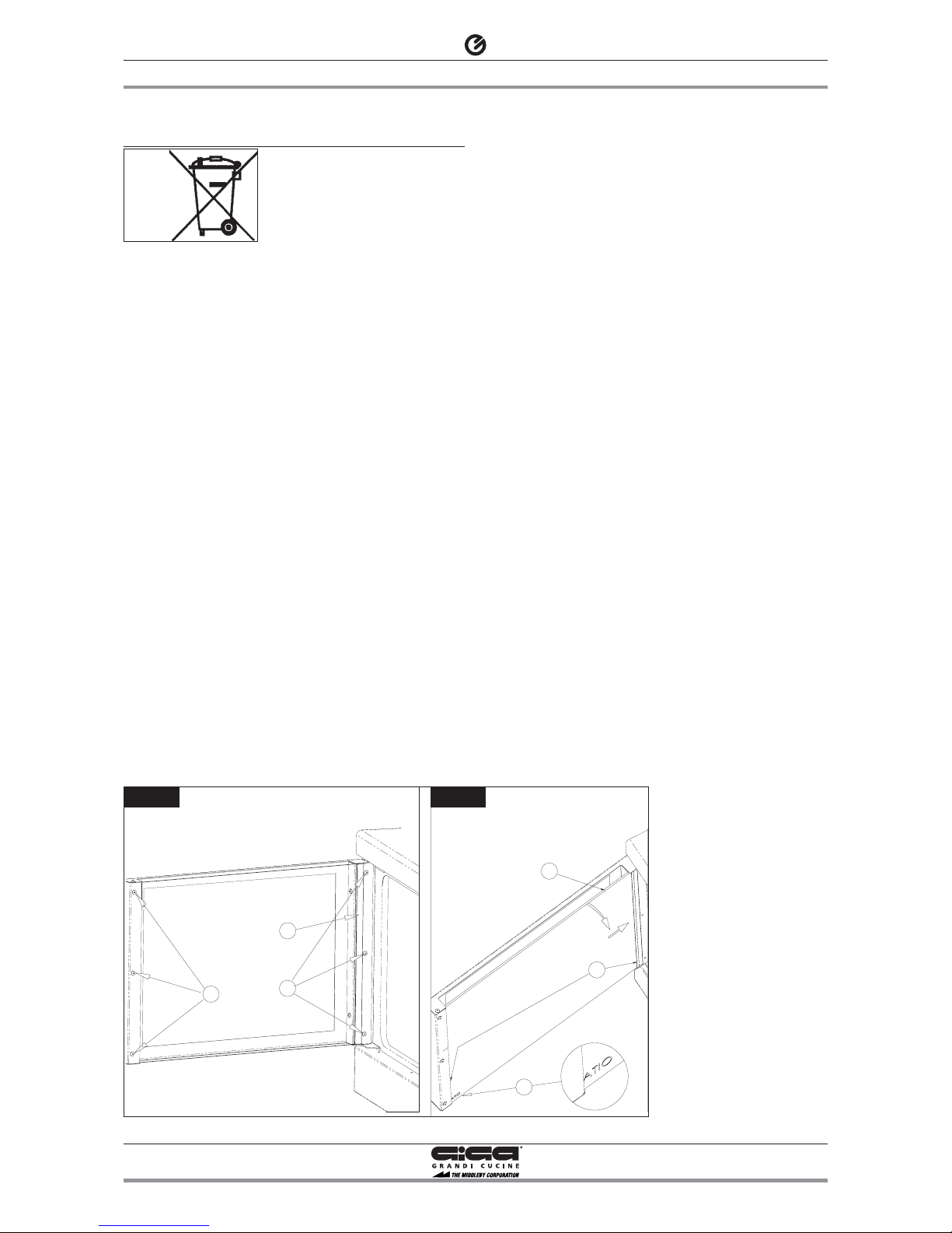
Glass must be cleaned when cool with a cloth dampened with water
and soap, rinsed and thoroughly dried. To facilitate cleaning
between the two sheets of glass, the internal sheet can be removed;
remove the glass fastening plate 1 (fig. 4) by unscrewing the screws
2 (fig. 4) and removing it from its housing, unscrew the screws 3
(fig. 4). Remove the glass 4 with the gaskets 5 (fig. 4A) by rotating it
(movement A) and sliding it from its housing (movement B).
Remove the gaskets from the glass, clean glass and gaskets.
Assemble all parts following these instructions in reverse order.
Caution! One side of the internal sheet of glass has been heat trea-
ted. This side is marked in white (ATIO fig. 4 pos. 4A) at the lower
left corner. The marked side must face the cooking chamber.
The gasket on the oven face can be cleaned with a cloth, water and
neutral soap, rinsed and dried. To facilitate cleaning, it can also be
removed from its housing by simply pulling it and cleaned with soap
and water. When cleaning, avoid bending gaskets with dry curves
which could deform its internal metallic core. Thoroughly dry the
gasket before reassembling it in its housing.
Caution! The manufacturer cannot accept liability or claims
under warranty for any damage to property resulting from
failure to observe the safety regulations, or from incorrect
installation. This also applies where the appliance is used by
the operator for purposes other than those for which it was
designed.