manuals.online logo
Brands
  1. Home
  2. •
  3. Brands
  4. •
  5. Gigabyte
  6. •
  7. Motherboard
  8. •
  9. Gigabyte MA10-ST Series User manual

Gigabyte MA10-ST Series User manual

This manual suits for next models

1

Other Gigabyte Motherboard manuals

Gigabyte GA-PH67A-UD3 User manual

Gigabyte

Gigabyte GA-PH67A-UD3 User manual

Gigabyte GS-W42G-P08R User manual

Gigabyte

Gigabyte GS-W42G-P08R User manual

Gigabyte GA-P67A-UD7 User manual

Gigabyte

Gigabyte GA-P67A-UD7 User manual

Gigabyte GA-H55M-D2H User manual

Gigabyte

Gigabyte GA-H55M-D2H User manual

Gigabyte MS03-CE0 User manual

Gigabyte

Gigabyte MS03-CE0 User manual

Gigabyte B460M GAMING HD User manual

Gigabyte

Gigabyte B460M GAMING HD User manual

Gigabyte GA-6KIEH-RH User manual

Gigabyte

Gigabyte GA-6KIEH-RH User manual

Gigabyte GA-6VTXE User manual

Gigabyte

Gigabyte GA-6VTXE User manual

Gigabyte GA-MA790GP-DS4H Manual

Gigabyte

Gigabyte GA-MA790GP-DS4H Manual

Gigabyte GA-MA790GP-DS4H User manual

Gigabyte

Gigabyte GA-MA790GP-DS4H User manual

Gigabyte GA-VM900M User manual

Gigabyte

Gigabyte GA-VM900M User manual

Gigabyte N4120I H User manual

Gigabyte

Gigabyte N4120I H User manual

Gigabyte GA-H81M-D2 User manual

Gigabyte

Gigabyte GA-H81M-D2 User manual

Gigabyte GA-H61M-USB3-B3 User manual

Gigabyte

Gigabyte GA-H61M-USB3-B3 User manual

Gigabyte B360N WIFI User manual

Gigabyte

Gigabyte B360N WIFI User manual

Gigabyte GA-6PMM User manual

Gigabyte

Gigabyte GA-6PMM User manual

Gigabyte GA - 686KX User manual

Gigabyte

Gigabyte GA - 686KX User manual

Gigabyte B660I AORUS PRO DDR4 User manual

Gigabyte

Gigabyte B660I AORUS PRO DDR4 User manual

Gigabyte GA-H61M-S2-B3 User manual

Gigabyte

Gigabyte GA-H61M-S2-B3 User manual

Gigabyte GA-7N400V User manual

Gigabyte

Gigabyte GA-7N400V User manual

Gigabyte MX31-CE0 User manual

Gigabyte

Gigabyte MX31-CE0 User manual

Gigabyte G1.Guerrilla User manual

Gigabyte

Gigabyte G1.Guerrilla User manual

Gigabyte 8I845GE-RZ User manual

Gigabyte

Gigabyte 8I845GE-RZ User manual

Gigabyte A520I AC User manual

Gigabyte

Gigabyte A520I AC User manual

Popular Motherboard manuals by other brands

DFI SD170 user manual

DFI

DFI SD170 user manual

ASROCK ROMED8-2T user manual

ASROCK

ASROCK ROMED8-2T user manual

Asus P2L97A user manual

Asus

Asus P2L97A user manual

Winmate IC70 user manual

Winmate

Winmate IC70 user manual

Asus MES-B user manual

Asus

Asus MES-B user manual

Grantech SYS8F377VGGA-3OMN user manual

Grantech

Grantech SYS8F377VGGA-3OMN user manual

Telit Wireless Solutions SL869-3DR user guide

Telit Wireless Solutions

Telit Wireless Solutions SL869-3DR user guide

Texas Instruments ADS8372EVM user guide

Texas Instruments

Texas Instruments ADS8372EVM user guide

Commell MS-C73 user manual

Commell

Commell MS-C73 user manual

IBT Technologies MB860 user manual

IBT Technologies

IBT Technologies MB860 user manual

Nvidia TEGRA DG-04927-001_V01 user guide

Nvidia

Nvidia TEGRA DG-04927-001_V01 user guide

Intel D33217CK specification

Intel

Intel D33217CK specification

Asus F1A55-M LX PLUS R2.0 user manual

Asus

Asus F1A55-M LX PLUS R2.0 user manual

EPC EPC9147C quick start guide

EPC

EPC EPC9147C quick start guide

Asus EX-B760M-V5 D4 quick start guide

Asus

Asus EX-B760M-V5 D4 quick start guide

EPOX MU-8KHA0010 user manual

EPOX

EPOX MU-8KHA0010 user manual

Ski-Doo Bombardier MPEM 219 700 090 user guide

Ski-Doo

Ski-Doo Bombardier MPEM 219 700 090 user guide

Epson S5U13700P00C000 user manual

Epson

Epson S5U13700P00C000 user manual

manuals.online logo
manuals.online logoBrands
  • About & Mission
  • Contact us
  • Privacy Policy
  • Terms and Conditions

Copyright 2025 Manuals.Online. All Rights Reserved.

Regulatory Noces Connect With Us
WEEE Symbol Statement
The symbol shown below is on the product or on its packaging, which indicates that this product must not be disposed of with other
waste. Instead, the device should be taken to the waste collecon centers for acvaon of the treatment, collecon, recycling and
disposal procedure. The separate collecon and recycling of your waste equipment at the me of disposal will help to conserve
natural resources and ensure that it is recycled in a manner that protects human health and the environment.
For more informaon about where you can drop off your waste equipment for recycling, please contact your local government
office, your household waste disposal service or where you purchased the product for details of environmentally safe recycling.
 When your electrical or electronic equipment is no longer useful to you, "take it back" to your local or regional waste
collecon administraon for recycling.
 If you need further assistance in recycling, reusing in your "end of life" product, you may contact us at the Customer Care
number listed in your product's user's manual and we will be glad to help you with your effort.
GIGABYTE产品未故意添加和使用有害物质(Cd、Pb、Hg、Cr+6、PBDE和PBB)。所有部件和元件均经过严格挑选,符合RoHS要求。此
外,我们GIGABYTE一直致力于开发不使用国际上禁止的有毒化学品的产品。
GIGABYTE products have not intended to add and safe from hazardous substances (Cd, Pb, Hg, Cr+6, PBDE and PBB). The parts and components
have been carefully selected to meet RoHS requirement. Moreover, we at GIGABYTE are connuing our efforts to develop products that do not use
internaonally banned toxic chemicals.
Restricon of Hazardous Substances (RoHS) Direcve Statement
限制使用有害物质 (RoHS) 指令声明
California Proposion 65 Warning
WARNING:
This product contains a chemicals , including lead, known to the State of California to cause cancer and birth defects or other reproducve harm.
For more informaon, please visit: hp://www.p65warnings.ca.gov/
Baery Warning:
Incorrectly installing a baery or using incompable baery may increase the risk of ifre explosion. Replace the baery only with
the same or equivalent type.
 Do not disassemble, crush, punchture baeries.
 Do not store or place your baery pack next to or in a heat source such as a fire, heatgenerang appliance, can or exhaust
vent. Heang baery cells to temperatures above 65oC (149oF) can cause explosion or fire.
 Do not aempt to open or service baeries. Do not dispose of baeries in a fire or with household waste.
电池警告:
电池安装不当或使用不兼容的电池会增加火灾爆炸风险。更换电池时,只可使用相同或同等类型的电池。
 请勿拆解、挤压、刺破电池。
 请勿将电池存放或放置在热源中或旁边,如火源、产生热的设备、罐体或排气口。电池温度升至65oC (149oF)以上
可能导致爆炸或火灾。
 请勿尝试打开或维修电池。电池废弃时,请勿投入火中或者作为家庭废弃物进行处理。
依照中华人民共和国的有毒有害物质的限制要求(China RoHS)提供以下的表格:
中华人民共和国电子信息产品中有毒有害物质或元素的名称及含量标识格式
For more informaon, visit our website at:
hp://b2b.gigabyte.com
You are a professional?
Get access to our complete source of sales & markeng materials at:
hp://reseller.b2b.gigabyte.com
Join our server forum to discuss our products and get technical assistance at:
hps://www.facebook.com/gigabyteserver
Front Panel Header/ 前面板 HDD Back Plane Board Header/ 硬盤背板排針
24
12
23
No. Pin Define
2 5V Standby
4 ID LED+
6 ID LED-
8 System Status LED+
10 System Status LED-
12 LAN1 Acve LED+
14 LAN1 Link LED-
16 SMBus Data
18 SMBus Clock
20 Case Open
22 LAN2 Acve LED
24 LAN2 Link LED-
No. Pin Define
1 BP_SGP_CLK
3 BP_SGP_GLD
5 BP_SGP_DOUT
7 Key Pin
9 GND
11 BP_LED_G_N
13 BP_SGP_DIN
15 GND
17 GND
19 P_3V3_AUX
21 P_3V3_AUX
23 GND
25 BP_PRESENSE
No. Pin Define
2 No Connect
4 FAN_SGP_GLD
6 GND
8 Reset
10 BP_LED_A_N
12 GND
14 No Connect
16 SMB_BP_DATA
18 SMB_BP_CLK
20 BMC_ACK
22 BMC_REQ
24 Key Pin
26 GND
No. Pin Define
1 Power LED+
3 No Pin
5 Power LED-
7 HDD LED+
9 HDD LED-
11 Power Buon
13 GND
15 Reset Buon+
17 GND
19 ID Switch+
21 ID Switch-
23 NMI Switch- 25 26
1 2
ATX Power/ 电源
113
12
24
84
51
PMBUS Memory Populaon Configuraon/ 安装内存
Type
Ranks PerDIMM
and
Data Width
1600, 1866, 2133, 2400*
1600, 1866, 2133, 2400*
1600, 1866, 2133, 2400*
1600, 1866, 2133, 2400*
1600, 1866, 2133, 2400*
1600, 1866, 2133, 2400*
1600, 1866, 2133, 2400*
1600, 1866, 2133, 2400*
1600, 1866, 2133, 2400*
1600, 1866, 2133, 2400*
1600, 1866, 2133, 2400*
1600, 1866, 2133, 2400*
Speed (MT/s);
Slot Per Channel (SPC) and DIMM Per Channel (DPC)
1 Slot Per Channel
1DPC
2 Slot Per Channel
1DPC 2DPC
RDIMM
RDIMM
RDIMM
RDIMM
SRx4 ECC
SRx8 ECC
DRx8 ECC
DRx4 ECC
 只使用一个DIMM时,必须先安装到内存DIMM_P0_A0插槽。
 若安装顺序有误,系统将不能正常引导。
 When only one DIMM is used, it must be populated in memory DIMM_P0_A0 slot first.
 System will not boot normally with incorrect populated sequence.
Rear I/O Connector/ 后面板接口
Mini SAS Connector/Mini SAS 接口
No. Pin Define
A1 GND
A2 SATA6G PORT0 RXP
A3 SATA6G PORT0 RXN
A4 GND
A5 SATA6G PORT1 RXP
A6 SATA6G PORT1 RXN
A7 GND
A8 No Connect
A9 No Connect
A10 No Connect
A11 No Connect
A12 GND
A13 SATA6G PORT2 RXP
A14 SATA6G PORT2 RXN
A15 GND
A16 SATA6G PORT3 RXP
A17 SATA6G PORT3 RXN
A18 GND
No. Pin Define
B1 GND
B2 SATA6G PORT0 TXP
B3 SATA6G PORT0 TXN
B4 GND
B5 SATA6G PORT1 TXP
B6 SATA6G PORT1 TXN
B7 GND
B8 No Connect
B9 No Connect
B10 No Connect
B11 No Connect
B12 GND
B13 SATA6G PORT2 TXP
B14 SATA6G PORT2 TXN
B15 GND
B16 SATA6G PORT3 TXP
B17 SATA6G PORT3 TXN
B18 GND
B1
A1
A18
B18
1
2
13
14
TPM Connector/ 可信平台模块
BMC F/W Readiness LED
State Descripon
On BMC firmware is inial
Blink BMC firmware is ready
Off AC loss
BMC Firmware Readiness LED (LED_BMC1):
CPU/System FAN/ 风扇
14 41
1
4
IPMB
Serial Port Cable Connector/ 串行端口
2
1
10
9
No. Pin Define
1 NDCD-
2 NSIN
3 NSOUT
4 NDTR-
5 GND
No. Pin Define
6 NDSR-
7 NRTS-
8 NCTS-
9 NRI-
10 No Pin
Jumper Sengs/ 跳线设置
No. Desripon
1 Clearing Supervisor Password Jumper
1-2 Close: Normal operaon. (Default seng)
2-3 Close: Skip supervisor password.
2 BIOS Recovery Jumper
1-2 Close: Normal operaon. (Default seng)
2-3 Close: BIOS recovery mode.
3 ME Recovery Jumper
1-2 Close: Normal operaon. (Default seng)
2-3 Close: ME recovery mode.
4 S3 Power On Select Jumper
1-2 Close: Stop an inial power on when BMC is not ready.
2-3 Close: Keep inial power on. (Default seng)
5 Clear CMOS Jumper
1-2 Close: Normal operaon. (Default seng)
2-3 Close: Clear CMOS data.
1
2 3
4
5
7
86
9
No. Pin Define
1 CLK
2 P_3V3_AUX
3 LPC_RST
4 P3V3
5 LPC_LAD0
6 IRQ_SERIAL
7 LPC_LAD1
8 No Connect
9 LPC_LAD2
10 No Connect
11 LPC_LAD3
12 GND
13 LPC_FRAME_N
14 GND
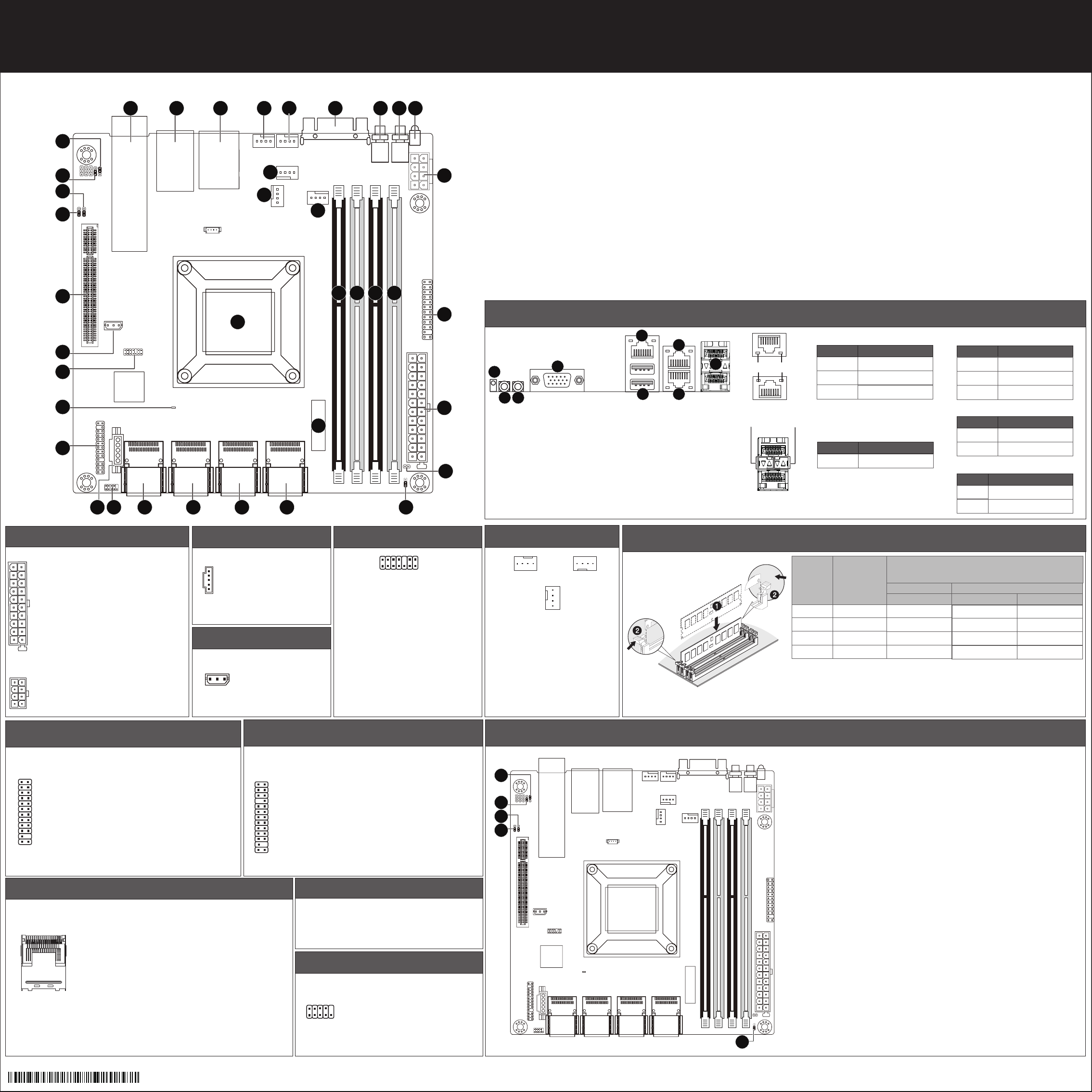
MA10-ST Series Quick Reference Guide/ 快速安装参考指南
5
13
1
No. Pin Define
1 3.3V
2 3.3V
3 GND
4 +5V
5 GND
6 +5V
7 GND
8 Power Good
9 5VSB
10 +12V
11 +12V
12 3.3V
No. Pin Define
1 GND
2 GND
3 GND
4 GND
No. Pin Define
1 PMBus Clock
2 PMBus Data
3 PMBus Alert
4 GND
5 3.3V Sense
No. Pin Define
1 Clock
2 GND
3 Data
No. Code Descripon
1 SFP+1_2 SFP+ LAN connectors#1/#2 (Based on SoC)
2 LAN_2 GbE LAN ports
3 USB_MLAN1 Serve management LAN port (top) / USB 2.0 ports (boom)
4 SYS_FAN 1 System fan connector #1
5 SYS_FAN 4 System fan connector #4
6 VGA_1 VGA port
7 SW_ID ID switch buon w/LED
8 SW_PWR Power buon w/LED
9 LED_STA System Status LED
10 P12V_AUX2 8 pin power connector
11 DIMM_P0_B0 Channel 3 slot 0
12 DIMM_P0_B1 Channel 4 slot 1
13 DIMM_P0_A0 Channel 1 slot 0
14 DIMM_P0_A1 Channel 2 slot 1
15 FP_1 Front panel header
16 ATX1 24 pin main power connector
17 CASEOPEN Case intruson alert header
18 CLR_CMOS Clear CMOS jumper
19 BAT1 Baery socket
20 CPU Intel® Atom™ C3000 Series SoC
No. Desripon
1 System Status LED
2 Power buon w/LED
3 ID switch buon w/LED
4 VGA port
5 KVM Server Management 10/100/1000 LAN Port (Dedicated LAN Port)
6 USB 2.0 ports
7 GbE LAN port (Share NIC)
8 GbE LAN port
9 SFP+ LAN ports
Off
State Description
Yellow On 1Gbps data arte
Green On 100Mbps data arte
10Mbps data arte
10/100/1000 LAN LED:
Speed LED Link/Acvity
LED
No. Code Descripon
21 MINI_CN1 Mini-SAS connector #1 (SATA3 6Gb/s signal)
22 MINI_CN2 Mini-SAS connector #2 (SATA3 6Gb/s signal/Based on SoC)
23 MINI_CN3 Mini-SAS connector #3 (SATA3 6Gb/s signal)
24 MINI_CN4 Mini-SAS connector #4 (SATA3 6Gb/s signal/Based on SoC)
25 COM1 Serial port cable connector
26 PMBUS PMBus connector
27 BP_1 HDD back plane board header
28 LED_BMC1 BMC firmware readiness LED
29 TPM TPM module connector
30 IPMB IPMB connector
31 PCIE_1 PCI Express x8 slot
Share bandwidth with MINI_CN2/MINI_CN3
MINI_CN2 and MINI_CN3 will be disabled when PCIe card is inserted
32 BIOS_PWD Clearing Supervisor Password jumper
33 BIOS_RCVR BIOS recovry jumper
34 ME_RCVR ME recovry jumper
35 S3_MASK S3 Power On Select jumper
36 SYS_FAN2 System fan connector #2
37 SYS_FAN3 System fan connector #3
38 CPU0_FAN CPU fan connector
Power buon/LED:
Green On
Off
Description
System is powered on
System is powered off
State
System Status LED:
Green On
Amber On
Off
Description
Normal operation
Critical alert.
System is not ready
State
No. Pin Define
13 3.3V
14 -12V
15 GND
16 PS_ON
17 GND
18 GND
19 GND
20 -5V
21 +5V
22 +5V
23 +5V
24 GND
No. Pin Define
5 +12V
6 +12V
7 +12V
8 +12V
No. Pin Define
1 GND
2 +12V
3 Sense
4 Speed Control
ID switch buon w/LED:
Blue On
Off
Description
Unit selected for identification
No identification
State
Speed LED Link/Acvity
LED
State Description
Green On 10 Gbps data rate
SFP+ LAN LED:
1 2 3 4 5 6 7 8 9
10
11
15
16
17
18
19
20
212223242526
27
28
29
30
31
32
33
34
35
36
37
38
121314
1
2
3
4
5
25ME0-MA1000-Q0R