1-2 ProductSpecications
CPU Support for 8th Generation Intel®Core™i7 processors/Intel®Core™i5 processors/
Intel®Core™i3 processors/Intel®Pentium®processors/Intel®Celeron®processors
in the LGA1151 package
(GotoGIGABYTE'swebsiteforthelatestCPUsupportlist.)
L3 cache varies with CPU
Chipset Intel®Q370 Express Chipset
Memory 4xDDR4DIMMsocketssupportingupto64GBofsystemmemory
Dual channel memory architecture
SupportforDDR42666/2400/2133MHzmemorymodules
SupportforECC Un-bufferedDIMM 1Rx8/2Rx8 memorymodules(operate in
non-ECCmode)
Supportfornon-ECCUn-bufferedDIMM1Rx8/2Rx8/1Rx16memorymodules
SupportforExtremeMemoryProle(XMP)memorymodules
* Tosupport2666 MHzorXMPmemory,youmustinstallan 8thGenerationIntel®
Core™i7/i5 processor.
(GotoGIGABYTE'swebsiteforthelatestsupportedmemoryspeedsandmemorymodules.)
Onboard
Graphics
Integrated Graphics Processor-Intel®HD Graphics support:
- 1xD-Subport,supportingamaximumresolutionof1920x1200@60Hz
- 1xDVI-Dport,supportingamaximumresolutionof1920x1200@60Hz
* TheDVI-DportdoesnotsupportD-Subconnectionbyadapter.
- 1xDisplayPort,supportingamaximumresolutionof4096x2304@60Hz
* SupportforDisplayPort1.2version,HDCP2.2,andHDR.
- 1xHDMIport,supportingamaximumresolutionof4096x2160@30Hz
* Support for HDMI 1.4 version and HDCP 2.2.
Support for up to 3 displays at the same time
Maximum shared memory of 1 GB
Audio Realtek®ALC887 codec
HighDenitionAudio
2/4/5.1/7.1-channel
* Tocongure7.1-channelaudio,youhavetouseanHDfrontpanelaudiomoduleand
enable the multi-channel audio feature through the audio driver.
LAN 2 x Intel®GbELANchips(10/100/1000Mbit)
TPM Inneonchip,supportingTPM2.0
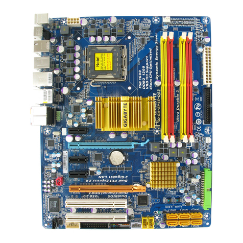
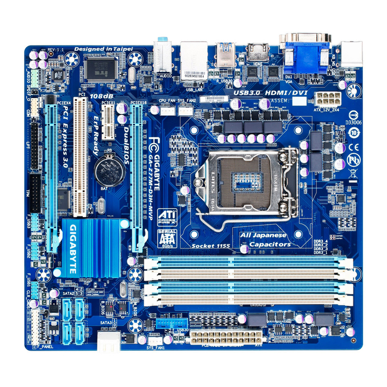
Expansion Slots 1xPCIExpressx16slot,runningatx16(PCIEX16)
* For optimum performance, if only one PCI Express graphics card is to be installed,
be sure to install it in the PCIEX16 slot.
1xPCIExpressx16slot,runningatx4(PCIEX4)
* ThePCIEX4slotsharesbandwidthwiththePCIEX1slot.WhenthePCIEX1slotis
populated, the PCIEX4 slot operates at up to x2 mode.
1 x PCI Express x1 slot
(AllofthePCIExpressslotsconformtoPCIExpress3.0standard.)
1 x PCI slot
1 x M.2 Socket 1 connector for an Intel®CNVioraPCIewirelessmodule(CNVI)
Multi-Graphics
Technology Support for AMD Quad-GPU CrossFire™and2-WayAMDCrossFire™technologies
- 6 -
