Gigafast EE2400-SV User manual

1
EE2400-SV
24 Ports Fast
Ethernet Switch
USER'S GUIDE

2
TABLE OF CONTENTS
1UNPACKING INFORMATION....................................................4
2PRODUCT INTRODUCTION......................................................5
2.1 MODELS.....................................................................................5
2.2 KEY FEATURES ..........................................................................5
2.3 FRONT PANEL ............................................................................6
2.3.1 10/100Mbps TP Ports........................................................6
2.3.2 Cabling..............................................................................6
2.3.3 Status LEDs.......................................................................6
2.4 REAR PANEL ..............................................................................6
2.4.1 Power Socket.....................................................................6
3INSTALLATION ............................................................................7
3.1 TO LOCATE THE SWITCH ON ADESKTOP......................................7
3.2 RACKMOUNT PLACEMENT..........................................................7
4HELPFULSUGGESTIONS ..........................................................8
4.1 PRIOR TO INSTALLATION ............................................................8
4.2 HALF-AND FULL-DUPLEX .........................................................8
4.3 FAST ETHERNET.........................................................................8
4.4 AUTO-NEGOTIATION..................................................................9
4.5 MACADDRESS TABLE...............................................................9
5SMART FUNCTION SETTINGS...............................................10
5.1 HARDWARE INSTALLATION.......................................................10
5.2 SOFTWARE INSTALLATION........................................................10
5.3 START SWITCH CONFIGURATION SOFTWARE............................11
6USE FUNCTION MENU .............................................................13
6.1 SWITCH CONFIGURATION SOFTWARE.......................................13
6.1.1 New .................................................................................13

3
6.1.2 Open................................................................................13
6.1.3 Model ..............................................................................14
6.1.4 About...............................................................................14
6.1.5 Exit..................................................................................14
6.1.6 24-Port Switch Configuration Software..........................15
6.2 SYSTEM BASE CONFIGURATION...............................................15
6.2.1 System Base Configuration Page....................................16
6.2.2 Packet drop if..................................................................16
6.2.3 Backoff operation mode ..................................................16
6.2.4 Address table mapping....................................................16
6.2.5 Address aging out............................................................17
6.2.6 Back pressure..................................................................17
6.2.7 Priority Setting................................................................17
6.3 PRIORITY SETTING...................................................................18
6.3.1 Priority Setting Page (Port Base) ...................................18
6.3.2 High/Low priority setting................................................18
6.3.3 IP base (TOS) priority recognition..................................19
6.3.4 VLAN tagging base (TCI) priority recognition ...............19
6.4 VLAN GROUP SETTING...........................................................19
6.4.1 VLAN Group Setting Pages(Port Base) ..........................19
6.4.2 VLAN Group 1 to 23 (G01 to G23).................................19
6.5 SPEED,DUPLEX,FLOW CONTROL SETTING ...............................20
6.5.1 802.3x Flow Control Setting (Port Base)........................20
6.5.2 Speed and Duplex Setting (Port Base)............................20
7PRODUCT SPECIFICATIONS ..................................................21

4
1 UNPACKING INFORMATION
Thank you for purchasing the Switch. Before continuing, please check the
contents of the product package. This product package should contain the
following items:
.One (1) Switch
.One (1) Software Disk
.One (1) Console Cable
.One (1) Power Cord
.Four (4) Rubber Feet
.One (1) Rackmount Kit
.This User’s Guide
If anything is missing, please contact your place of purchase.
24-Port 100BASE-TX Fast Ethernet Switch
Power Cord Rubber Feet
Rackmount Kit (Optional) User’s Guide
Software Disk Console Cable

5
2 PRODUCT INTRODUCTION
2.1 Models
The Switch is a multi-speed, versatile network device combining both standard
and "Big-Pipe" ports under the same hood. The Switch is a Twenty-Four (24)
ports Fast Ethernet Switch.
2.2 Key Features
.Support QoS function based on IEEE 802.1p/802.1q port priority, VLAN tag
priority and TCP/IP header’s TOS/DS.
.Supports VLAN, up to 24 group VLANs.
.Provide console port and software for easy configuration.
.Store-and-Forward technology filtering/forwarding is used to eliminate bad
packets.
.Back-Pressure Flow-Control support for Half-Duplex operation.
.IEEE802.3x Flow-Control support for Full-Duplex operation.
.All connectors and LEDs on front panel for easy access and real time viewing
of Switch status.
.All TP ports support Auto-MDI/MDIX, and Auto-Negotiation function.

6
2.3 Front Panel
2.3.1 10/100Mbps TP Ports
Each 10/100Mbps TP port provides an Auto-Negotiation function that senses for
the attached device's maximum operating speed and automatically sets the
Switch to operate at that speed. Users only need to connect a network device
into any TP port. Auto-MDIX is also supported on all TP ports which allows
uplinking to another Switch free of cross-over or straight cable selection hassle.
2.3.2 Cabling
10Mbps -When transmitting at 10Mbps Category 3, 4 or 5 TP cabling with
RJ-45 sockets can be used.
100Mbps -To transmit at 100Mbps requires Category 5 TP cabling.
Port Type Cable Type Connector
10BASE-T Category 3, 4 or 5 TP RJ-45
100BASE-TX Cat.5 TP RJ-45
Note: Category 5 UTP cable is recommended whenever installing new cabling.
2.3.3 Status LEDs
The Switches come with a complete range of LEDs. The table below lists each
LEDs name, color and a brief description of its function.
Name Color Function
Pwr Green Lit: Power "On"
LINK/ACT Green Lit: When the port has a valid physical connection with another
device.
Blinks: When the port is sending or receiving data (Activity).
FD/COL Amber Lit: When the port is set to Full-Duplex mode.
Blinks: When a collision is detected, when the port is in
Half-Duplex mode.
2.4 Rear Panel
2.4.1 Power Socket
The Power Socket is designed to be used with the power cord included in the
product package.
.Attach the female end of the cord to the power connector on the back panel.
.Attach the male end of the cord to a grounded power outlet.

7
3 INSTALLATION
The Switch is "Plug-&-Play". It does not require software configuration. Users
can immediately use any of the features of this product simply by attaching the
cables and turning on the power.
If user need advanced smart functions to manage LAN network more effectively,
we provide software and cable for easy configuration of the Switch. Please see
section 5 and 6 for further details.
3.1 To locate the switch on a desktop
.Attach the Four (4) rubber feet included in the product package to the bottom
of the Switch, one in each corner.
.Place the Switch on a clean, flat desk or tabletop close to a power outlet.
.Plug in all network connections and the power cord, and Power “ON”.
3.2 Rackmount placement
.Attach One (1) rackmounting bracket on each side of the Switch front panel
and secure each bracket with the provided screws.
.Use the other provided screws to secure each Switch to the rack.
Use the other provided screws to secure each Switch to the rack.

8
4 HELPFUL SUGGESTIONS
4.1 Prior to Installation
Before installing the Switch and connecting network devices, it is important to
plan the network's layout. Things you should consider include:
.Dedicated Bandwidth: File servers and other high-traffic hardware improve
their performance if they have their own dedicated 10Mbps or 100Mbps
bandwidth.
.Full-Duplex: Determine which devices support Full-Duplex connections.
.Fast Ethernet: Make sure rules for cable lengths and categories are followed.
.Auto-Negotiation: Devices with different speeds may be easily swapped
when the other end of the cable is fixed to a port with Auto-Negotiation.
4.2 Half- and Full-Duplex
The Switch supports both Half- and Full-Duplex modes for 10BASE-T and
100BASE-TX.
.In Half-Duplex mode: Data cannot be transmitted and received at the same
time. Attached devices must finish transmitting data before they can receive
data.
.In Full-Duplex mode: Data can be transmitted and received at the same time.
However:
.Full-Duplex transmission is only possible between two devices with a
dedicated link (ex: Switch-Switch, Switch-PC)
.Both devices must have Full-Duplex capability
.Both devices must be set to Full-Duplex (ex: Auto-Negotiation –
Auto-Negotiation, Non-Auto-Negotiation to Non-Auto-Negotiation)
The 100BASE-TX/10BASE-T ports on the Switch detect and set the line's
operating mode by using their Auto-Negotiation function.
4.3 Fast Ethernet
100BASE-TX is called "Fast Ethernet". In Fast Ethernet data travels ten times
faster (100Mbps) than in traditional Ethernet (10Mbps).
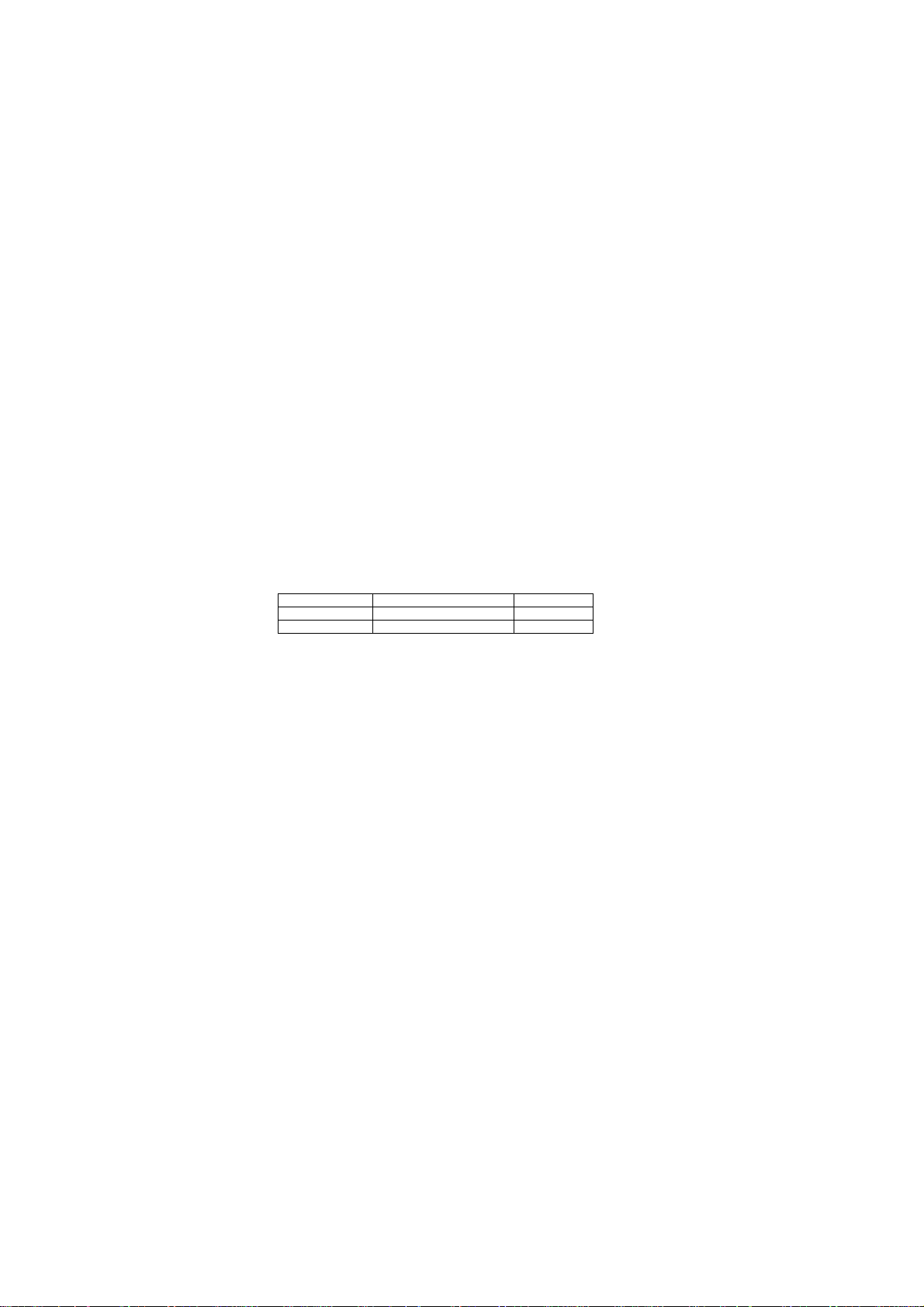
Below is a list of the cable types and connectors supported by the Switch for
10BASE-T and 100BASE-TX networks.
Port Type Cable Type Connector
10BASE-T Category 3, 4 or 5 TP RJ-45
100BASE-TX Cat. 5 TP RJ-45
Note: If your 10BASE-T network currently uses Category 5 TP cabling, you can
instantly upgrade the network to a 100BASE-TX network by changing network
devices.

9
4.4 Auto-Negotiation
Every 10/100Mbps dual speed port on the Switch has a Built-In
"Auto-Negotiation" function. This technology automatically sets the best
possible bandwidth as soon as a connection is established with another
network device. (Usually at Power “On” or Reset.) This capability is achieved
via the Switch’sAuto-Negotiation function that automatically detects the modes
and speeds the second (attached) device is capable of.
Evaluating Auto-Negotiation Capability:
If attached device is: The Switch will automatically set its TP ports to
operate at:
100Mbps
no Auto-Negotiation 100Mbps (100BASE-TX, Half-Duplex)
100Mbps
with Auto-Negotiation 200Mbps (100BASE-TX, Full-Duplex)
10Mbps
no Auto-Negotiation 10Mbps (10BASE-T, Half-Duplex)
10Mbps
with Auto-Negotiation 20Mbps (10BASE-T, Full-Duplex)
Note: If the attached device is set to a fixed mode (ex: Forced Full-Duplex) it
will not operate as an Auto-Negotiation device.
4.5 MAC Address Table
Every Ethernet data packet includes both source and destination addresses.
This Six (6)-bytes ID is called the MAC (Media Access Control) Address.
The Switch can automatically learn and store MAC addresses. However, the
MAC address table is volatile: it disappears when the Switch is powered “Off” or
reset.
Note: When the network needs reconfiguration, we recommend turning off the
power first. After all nodes have been moved, turn the Switch back "On" to
rebuild the internal MAC address table.

10
5 SMART FUNCTION SETTINGS
5.1 Hardware installation
The Switch has a smart function that you can use to manage your Local Area
Network (LAN) more effectively. You also can use the default setting to make
the Switch operate as a dumb switch.
If you want to use smart function, install the Switch as below:
Use the Printer Cable to connect the Switch to a computer. Connect One (1)
cable end to the Switch, and connect the other end to the computer’s “LPT”
port.
5.2 Software installation
First, you should execute setup program to install the software.
Listed below shows the disk label, execute setting up file and the default
installation path.
Disk label Setting up file Default installation path
24 Port switch
software Txsetup.exe C:\Program Files\PureTX
Click Start to continue.
The configuration software should be installed with the following Menu shown
on the Computer Screen.
After installed completely, please click OK when the following Menu is shown.

11
Now you can execute the program to configure your Switch.
5.3 Start Switch Configuration Software
When you start the program, if you see the screen as shown below, it indicates
that the Switch is either not power on or the LPT cable is disconnected. You
need to check the power cord and the LPT cable connection.
When the message “Switch is not connected or the switch type is not
recognizable. Do you want to continue?” pop-up, you can press Yto continue or
Nto exit.
If you see the message shown below, it means that the program has found the
Switch.

12
Please click OK to continue.
If you see the screen shown below, you can use the software correctly.
Note: Any configuration you have changed, we recommend that you un-plug
the power cord and reconnect it again to reboot the Switch settings in order to
maintain proper functioning of the Switch.

13
6 USE FUNCTION MENU
6.1 Switch Configuration Software
New Create a new switch configuration file.
Open Open an existing switch configuration file.
Model Supported models introduction.
About Information about this switch configuration software.
Exit Close this program.
6.1.1 New
First time you use the software to configure the Switch, you can select New, to
setup the Switch’s configuration.After you click New, the following message
pop-up. You can select Auto Detect for automatically detect the current Switch
or select existing Switch’s model name for configuration.
6.1.2 Open
If you want to open your configuration setting file you had already saved, you
can select Open and open the saved file from your harddisk. If the settings of
the opened file is not the same as the current Switch settings, the following
message would be pop-up and alert you. You should be careful when writing

14
settings to Switch. You can click OK to continue using the opened configuration.
6.1.3 Model
You can select the specific model by click Model selection. The following
message shows how many and what the Switch Models you could select.
If you select the model which doesn’t match the current switch you connect, the
following message should pop-up and warn you.
6.1.4 About
This will show the versions of the software and copyright.
6.1.5 Exit
You can click Exit to close the software. It will pop-up the following confirmation

15
message.
6.1.6 24-Port Switch Configuration Software
After the program correctly installed to the Switch, you can now setup the
Switch by the Switch Configuration Software.
There are Four (4) setting pages for the switch configuration:
•System Base Configuration
•Priority Setting
•VLAN Group Setting
•Speed, Duplex, Flow Control Setting
6.2 System Base Configuration
Default You can use Default setting or modify the setting by
yourself.
OK If you click OK after modifying the settings, the following
message would pop-up. You can click Yes to save the
modified settings to the Switch and save the Switch
Configuration File (default name is Mxcfg24) to your
harddisk. If you click No, the modified settings will only
be saved to the Switch but will not be saved to the
harddisk.
Cancel If you click Cancel, the Switch will not be changed.

16
Apply After the setting is modified, click Apply to change the
Switch’s settings immediately.
6.2.1 System Base Configuration Page
All the settings made in this page will take effect in the system of the Switch.
6.2.2 Packet drop if
There are two packet drop conditions, one is when packet encounters 16-time
collisions and the other is packet timeout.
Having the check mark on each box will enable corresponding packet drop
condition.
item description
Continuous
16-time
collision
If you enable this check mark, the same packet that
runs into 16 consecutive collisions will be dropped.
Timeout If you enable this check mark, packet will be
dropped when the packet being queued over 1
second
The IEEE standard specifies the packet drop if it runs into 16 consecutive
collisions. For some performance reason, you can disable the function by
unmark Continuous 16-time collision item, and the Switch will retransmit the
packet after 16 consecutive collisions.
Default: setting Continuous 16-time collisions.
6.2.3 Backoff operation mode
Set the switch backoff operation mode. Standard mode or SuperMAC mode.
Note: SuperMAC means when collision occurrs, the Switch will reduce the
random waiting time to retransmit the packet.
Default: setting Standard mode.
6.2.4 Address table mapping
Tell the switch how to map MAC address to its address table.
You can use CRC calculation to get the hashing index of address table direct
mapping to enable the whole address table mapping.
Note: 48-bit DA/SA address is translated separatly into 12-bit entry pointer of
address table for address learning and recognition. The translation is by aid of
CRC generator within the switch controller. The index of entry pointer selection

17
is defined by the following selection.
•CRC hashing bit [11:0]
•CRC hashing bit [16:5]
•CRC hashing bit [24:13]
•CRC hashing bit [30:19]
Note: Direct mapping: It means DA/SA addresses are directly used as an index
of address table.
Default: setting CRC hashing bit [11:0]
6.2.5 Address aging out
If the dynamically learned Source Address will be cleared if it is not refreshed in
less than programmed time.
Only when you enable address aging out, aging timer would be active. You can
setup the aging timer from 0 to 24 hrs and from 0 to 59 min.
Note: Aging timer provides for address table. The timer period is defined to age
out the least unused entries on address table.
Default: setting Enable aging time about 5 minutes.
6.2.6 Back pressure
You can enable Back-Pressure Flow-Control on half duplex connection for all
ports.
Default: setting Enable
6.2.7 Priority Setting
If you enable the function, it has two priority subitem:
•All high then low priority packet
•Set priority transmission ratio
Note: The Switch supports 3 types of QoS functions to improve multi-media or
real-time network applications. The QoS function based on IEEE802.1p/802.1q
port priority, VLAN tag priority, and TCP/IP header’s TOS/DS.
Only when you check the Enable priority setting box at System Base
Configuration page, then the Priority Setting page will be active.
•All high then low priority packets
•Set priority transmission ratio
All high
then low
priority
packets
Tell the Switch transmit all the high priority packets
first, then the other low priority packets.
Set priority
transmissio
n ratio
Tell the Switch make a transmission ratio of the
high/low priority packet.
The default high/low ratio is 5:1. You can make the
ratio by yourself from 1 to 7 of high or low ratio.
Default: setting Enable and All high then low.

18
6.3 Priority Setting
6.3.1 Priority Setting Page (Port Base)
There are Three (3) kinds of priority settings:
•High/Low priority setting
•IP Base (TOS) priority
•VLAN tagging base (TCI) priority
Before you can do the priority setting, you have to check the Enable priority
setting box at System Base Configuration page.
Class of Service denotes the classification of traffic used to differentiate
services among traffic classes. The Switch offers 2-level priority (High and Low)
queues, which catch the priority information in the TOS field, port base, or
VLAN tag in the incoming frames as IEEE 802.1p/802.1q standard defines. In
this way, the switch controller guarantees the service for high priority frames to
some extent, depending on the load condition of incoming traffic. (At least, the
high priority service offers better than that of best effort service.) It also provides
different service ratio settings for users to shape the prioritized frames on the
streams in the incoming traffic.
6.3.2 High/Low priority setting
Specify high or low priority for each port. The port is in High priority if the port
has a check mark, otherwise, the port is in Low priority.
Each port has 2 priority queues for transmit. When both queues have data at
the same time, packet delivery will follow high/low ratio.
Default: setting all port in Low priority

19
6.3.3 IP base (TOS) priority recognition
Ports with TOS enabled will induce switch to inspect the specific field of IP
packet to control packets priority. Making a check mark in front of port id
indicates this port is TOS priority recognition enabled.
Default: setting all port in TOS priority recognition disabled.
6.3.4 VLAN tagging base (TCI) priority recognition
Making a check mark in front of port id indicates this port is TCI priority enabled.
Default: setting all port in TCI priority recognition disabled.
6.4 VLAN Group Setting
There is One (1) default group (G00) and Twenty-Three (23) user defined
groups (from G01 to G23). You can click Change to VLAN group 0 to 11 or
Change to VLAN group 12 to 23 to switch the group page for setting.
6.4.1 VLAN Group Setting Pages(Port Base)
Organize your Virtual LAN (VLAN) groups in this page. In this version, you can
set at most 24 VLAN groups. Usually, group 0 is default group and not allowed
for user to use.
6.4.2 VLAN Group 1 to 23 (G01 to G23)
Grouping user with the same attribute provides flexible network managing.
Users in the same group can have a group name to name it, i.e. in the Group
name field. To config a VLAN group, you should need just to check all the ports
belonging to the same group and leave the others unchecked.
Default: setting all ports in the same VLAN group G00. After you click Apply,

20
you can check group 0 G00 to see if any ports are left out for setting.
6.5 Speed,Duplex,Flow Control Setting
6.5.1 802.3x Flow Control Setting (Port Base)
Specify IEEE 802.3x Flow-Control mechanism for each port.
Enable 802.3x Flow-Control:
IEEE 802.3x Flow-Control can avoid lost packets due to traffic congestion on
egress ports.
Default: setting Enable and all port in IEEE 802.3x Flow-Control.
6.5.2 Speed and Duplex Setting (Port Base)
Each port can operate in Auto Negotiation mode and force mode, i.e.
100Mbps/Full duplex, 100Mbps/Half duplex, 10Mbps/Full duplex, and
10Mbps/Half duplex.
Speed/Duplex setting:
You can specify the speed and duplex setting manually for each port if
necessary. Usually Auto is OK, only when the port connected to other side of
device which is set to forced mode, you need to specify the match setting for
the port.
Default: setting all port in Auto-Negotiation mode.
Note: a. If the port set to forced mode, the IEEE 802.3x Flow-Control will be
inactive.
b. If the Switch has 100BASE-FX fiber port; the fiber port will only support
force to 100Mbps Half-Duplex or 100Mbps Full-Duplex mode.
Default: setting 100Mbps Full-Duplex mode.
Table of contents
Other Gigafast Network Router manuals
Popular Network Router manuals by other brands

Cisco
Cisco Linksys E900 user manual

MA lighting
MA lighting MA Switch Quick manual

Cradlepoint
Cradlepoint MBR1400 Series Setup guide

ZyXEL Communications
ZyXEL Communications XMG3512-B10A quick start guide

PROLiNK
PROLiNK Hurricane 9200/S Quick installation guide

Alcatel
Alcatel OmniAccess 600- series quick start guide

Siemens
Siemens 4100 Series user guide

NetComm
NetComm NF20 quick start guide

Romantis Satellite Communications
Romantis Satellite Communications UHP-1000 Installation and operation manual

ZyXEL Communications
ZyXEL Communications P-2302R-P1C Firmware release notes

Buffalo
Buffalo AirStation Nfiniti WZR-HP-AG300H user manual

XtendLan
XtendLan XL-EFM404V user manual