Gigawave D-Cam Clip-On User manual

D-Cam Clip-On Operators Manual Issue 1 Page1of 1
UNUM-CCAM-0104
The information contained in this manual remains the property of Gigawave and may not
be used, disclosed or reproduced in any other form whatsoever without the prior written
permission of Gigawave.
D-Cam Clip-On
OPERATORS MANUAL
Copyright 2005 Gigawave Limited

D-Cam Clip-On Operators Manual Issue 1 Page2of 2
UNUM-CCAM-0104
CONTENTS
1GENERAL SAFETY INFORMATION.....................................................................................3
1.1 Health & Safety......................................................................................................................4
1.2 Maximum RF Power Density Limits ...................................................................................5
1.3 Issue Status............................................................................................................................5
2INTRODUCTION.......................................................................................................................6
3SYSTEMOPERATION............................................................................................................8
3.1 Camera Interfaces.................................................................................................................8
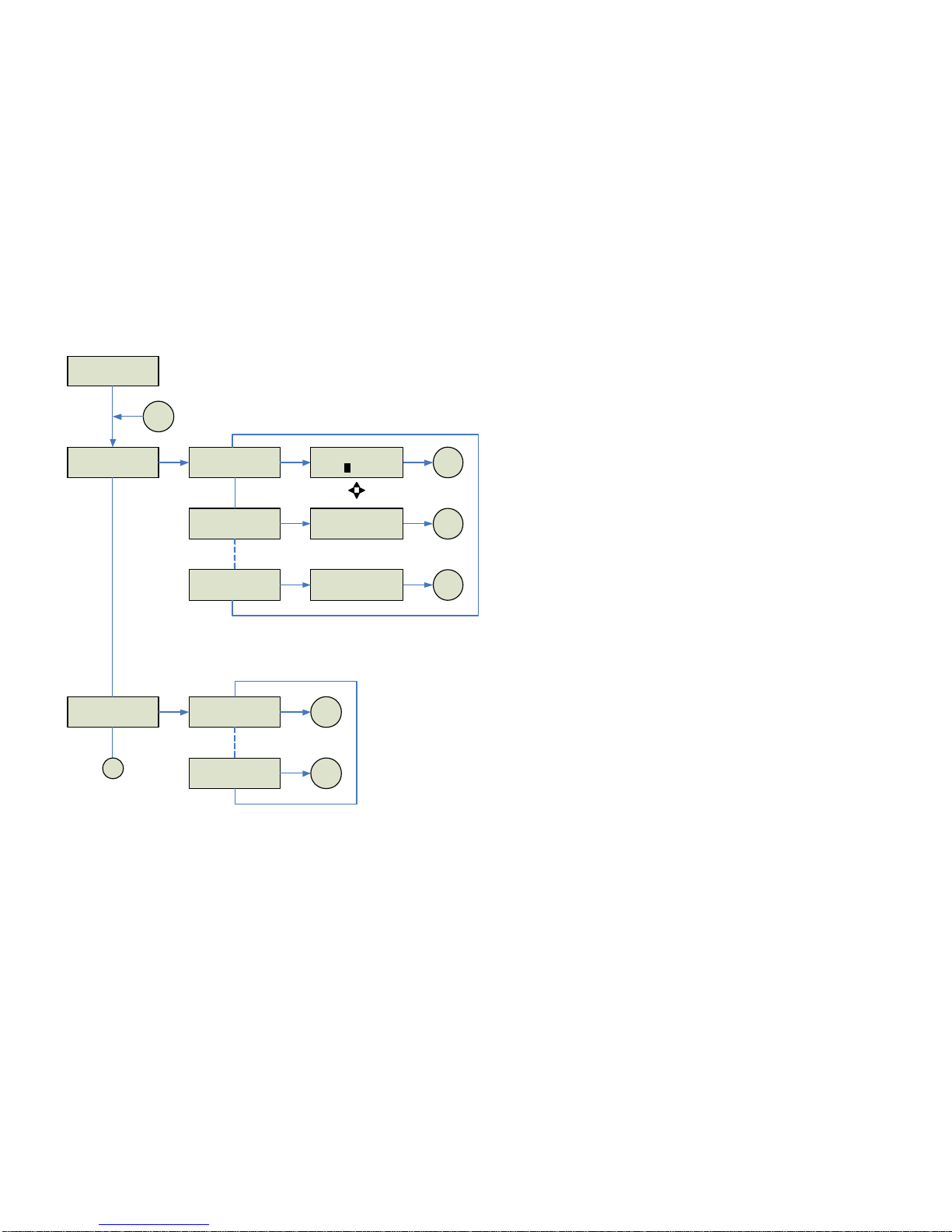
3.2 Operator Controls / Menus..................................................................................................8
3.2.1 Initialisation Menu..........................................................................................................8
3.2.2 Main Menu......................................................................................................................8
3.2.3 Ch / Frequency Menu.................................................................................................12
3.2.4 Encoder Menu..............................................................................................................12
3.2.5 Audio 1 Menu...............................................................................................................12
3.2.6 Audio 2 Menu...............................................................................................................12
3.2.7 Status Menu.................................................................................................................12
3.3 Status Monitoring................................................................................................................13
3.4 System Configuration –Engineering Menu....................................................................13
3.4.1 ProgChannels.............................................................................................................13
3.4.2 FW Inventory................................................................................................................13
3.4.3 Video Input ...................................................................................................................13
3.4.4 Video Format................................................................................................................14
3.4.5 Temperature.................................................................................................................14
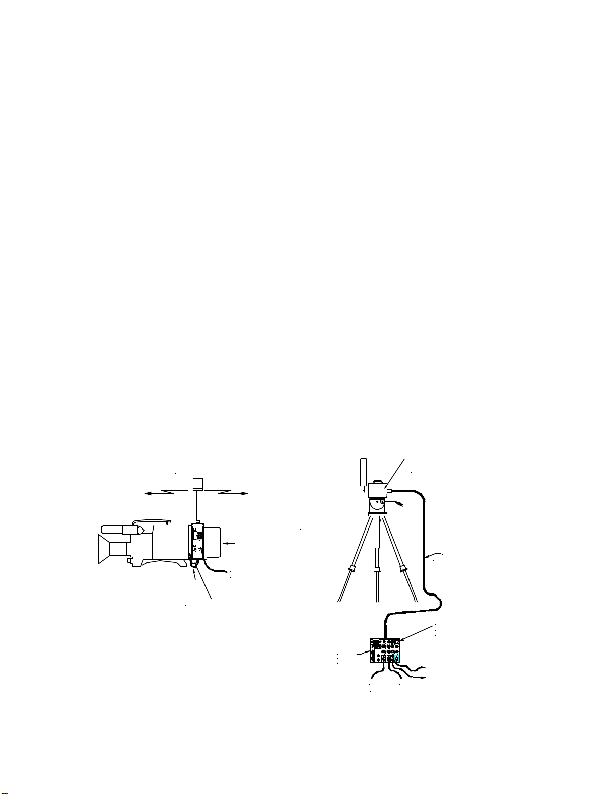
4PREPARING FOR OPERATION..........................................................................................18
4.1 The D-CamClip-On Camera Back...................................................................................18
4.2 The Receiving Equipment..................................................................................................18
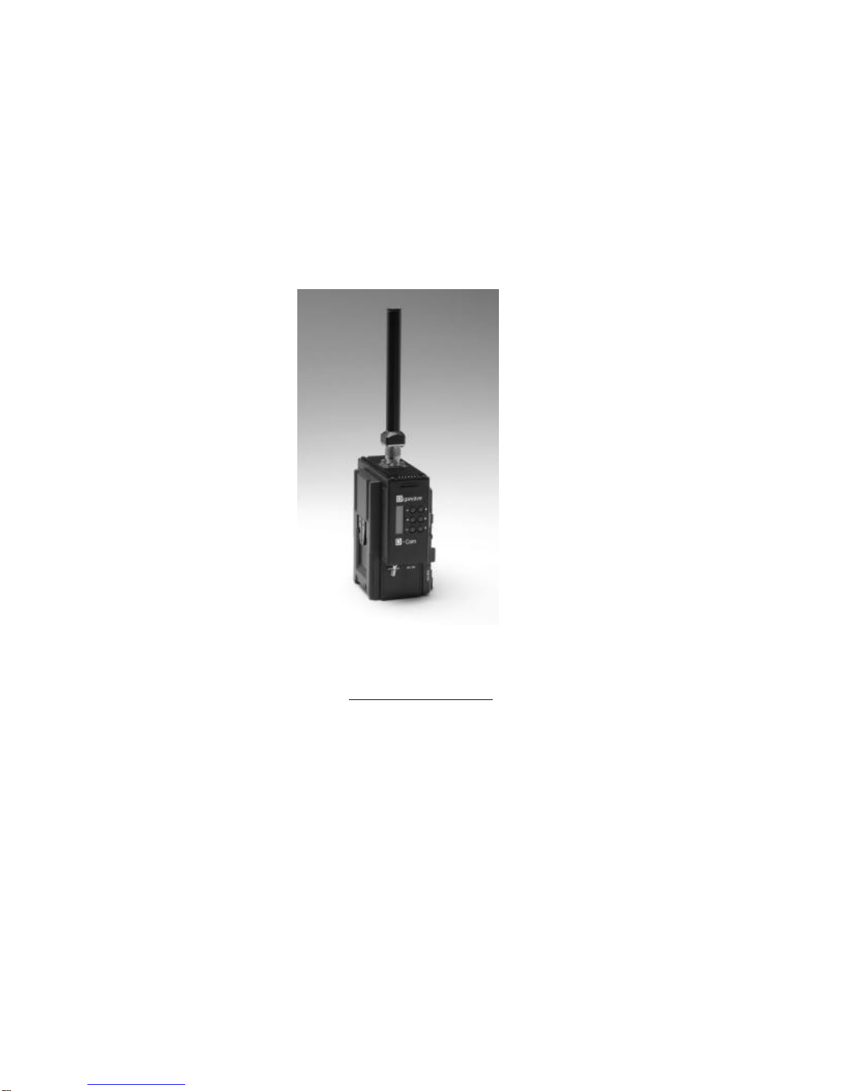
5D-CamClip-On Transmitter...................................................................................................20
5.1 Connector Pin Outs.............................................................................................................20
5.1.1 SDI / CVBS Video BNC..............................................................................................20
5.1.2 Video Connector..........................................................................................................20
5.1.3 Audio Connector..........................................................................................................21
5.1.4 Power Connector.........................................................................................................21
5.1.5 Remote Connector......................................................................................................21
5.2 Audio / Video Encoder........................................................................................................22
5.3 COFDM Modulator..............................................................................................................23
5.4 Power Amplifier....................................................................................................................24
5.5 Front Panel...........................................................................................................................24
5.5.1 DefaultParameterSet................................................................................................25
6System Monitoring / Setup.....................................................................................................26
6.1 Main Menu............................................................................................................................26
Program Channels ......................................................................................................................27
6.2.1 List All Channels..........................................................................................................27
6.2.2 Program Channel........................................................................................................28
6.3 Dump Setup.........................................................................................................................29
6.4 Unit Name.............................................................................................................................30

D-Cam Clip-On Operators Manual Issue 1 Page3of 3
UNUM-CCAM-0104
1GENERAL SAFETY INFORMATION
The information that follows, together with local site regulations, must be studied by
personnel concerned with the operation or maintenance of the equipment, to ensure
awareness of potential hazards.
WARNING-RF Power Hazard : High levels of RF power are present in the unit. Exposure
to RF or microwave power can cause burns and may be harmful to health.
Switch off supplies before removing covers or disconnecting any RF cables, and before
inspecting damaged cables or antennas.
Avoid standing in front of high gain antennas (such as a dish) and never look into the open
end of a waveguide or cable where RF power may be present.
Users are strongly recommended to return any equipment that requires RF servicing to
Gigawave.
WARNING-GaAs / BeO Hazard :Certain components inside the equipment contain
Gallium Arsenide and Beryllium Oxide that are toxic substances. Whilst safe to handle
under normal circumstances, individual components must not be cut, broken apart,
incinerated or chemically processed. In the case of Beryllium Oxide, a white ceramic
material, the principal hazard is from the dust or fumes, which are carcinogenic if ingested,
inhaled or entering damaged skin.
Please consult your local authority before disposing of these components.
CAUTION-Tantalum Capacitors: When subjected to reverse or excess forward voltage,
ripple current or temperature these components may rupture and could potentially cause
personal injury.
CAUTION: This system contains MOS devices. Electro-Static Discharge (ESD)
precautionsshould be employed to prevent accidental damage.
This device complies with part 15 of the FCC Rules. Operation is subject to the following
two conditions: (1) This device may not cause harmful interference, and (2) this device
must accept any interference received, including interference that may cause undesired
operation.
FCC Part 15.21
Changes or modifications not expressly approved by the party responsible for compliance
could void the user's authority to operate the equipment.
NOTE: The manufacturer is not responsible for any radio or TV interference caused by
unauthorized modifications to this equipment. Such modifications could void the user's
authority to operate the equipment.

The unit is supplied with a 4dBi antenna that is fitted to the rear of the camera. The FCC RF
Exposure Evaluation has determined that a 20cm minimum safety distance must be maintained
between the antenna and all persons in the area.
Use of the unit with an external mast mounted antenna and / or power amplifier requires separate
RF Exposure Evaluation.


D-Cam Clip-On Operators Manual Issue 1 Page6of 6
UNUM-CCAM-0104
2INTRODUCTION
This manual is to be used in conjunction with the D-Cam Clip-On unit (CCAM-0104) which
replaced the original 0101 & 0102 variants. The upgrade from 0101 to 0102 added the
extra feature of an SDI input. The upgrade from 0102 to 0104 added the extra features of
frequency selection to 0.5MHz increments. For details of the receiver please refer to the
relevant manual.
The Gigawave D-Cam Clip-On Wireless Camera system is designed for all applications,
both indoor and outdoor, in which a mobile camera is essential to the televised programme
production. The unique modular design of the Gigawave D-Cam Clip-On ensures
complete flexibility to change compression and modulation techniques to suit each
individual task required, from low delay or to the most rugged of RF signal paths.
The system is comprised of the Clip-On transmitter that contains an audio encoder, video
encoder, COFDM modulator, power supplies and an RF power amplifier. Attached directly
to this transmitter is an omni-directionalantenna.
At the receive site the MVL-D two-box digital Receiver is used. No external decoders or
demodulators are required with this Receiver. The MVL-D is a two box rugged portable
system developed from proven technology from the analogue MVL series of Receivers
and Transmitters.
3.15AMP
AGC
INT
A2A1VID
A3
A4
CLAMP
VIDEO
OFF
ON
SAW
POWER
-80 -70 -60 -20-30-40-50
RECEIVELEVELdBm
IN
OUT
OFF
ON
INV
NOR
AUDIOS 3 & 4AUDIOS1 & 2
+3-3
dB
0
+3-3
dB
0
AUDIO1 AUDIO3
2 AMP
70MHzIFOUT
CHANNEL1
2
3
45
6 78
910
11
12
MAN
110/230V AC
10-30VDC
MONITOR
AUDIO4AUDIO2
+3-3
dB
00
dB
-3 +3
0
dB
-3 +3
VIDEO
REMOTE
BASEBAND
INTERCOM
4321
GIGAWAVE
-
+
35
+
-
0
+
-
0
+
--
+
0
-
+
0
-
+
53
+
-
GIGAWAVE
LOCALALARMVIDEO ALARM
CONTROL HEAD
INTERCOMMONITOR
battery pack
cameraman's battery belt
DC input from
(up to 600 Metres)
'Triax' cable
and fanbeam antenna
Receive Head unit
MVL-D
A1 A2
MVL-D
Receive
Control
Audio Outputs
- analogue or AES/EBU digital
SDI output 270 mbps
ANALOGUE output
Digital low power
transmission
MVL Control unit with
integral digital decoder
and COFDM demodulator
unit
Tripod-mounting or
pole-mountable bracket
-Cam
OFF
D
12V DC
igawave
EC
G
Optional
Video cable
Audio cable

D-Cam Clip-On Operators Manual Issue 1 Page7of 7
UNUM-CCAM-0104
External Views of the D-Cam Clip-On
RF OUTPUT POWER
AMPLIFIER BATTERY
CLIP
CAMERA
INTERFACE
CE
12V DC
-Cam
D
igawave
G
SDI
VIDEO
D
-Cam
G
igawave
STATUS
LED
OFF
AUDIO
ON

D-Cam Clip-On Operators Manual Issue 1 Page8of 8
UNUM-CCAM-0104
3SYSTEM OPERATION
3.1 Camera Interfaces
The D-CamClip-On can be supplied with one of three battery and camera interfaces:
•Sony ‘V’ Block / IDX
•Anton Bauer Gold Mount
•PAK
These provide a flexible and versatile mounting system suitable for a wide range of
cameras and battery options.
The D-Cam Clip-On is first mounted onto the camera rear battery interface. If required, an
appropriate battery can then be docked onto the rear of the D-Cam Clip-On transmitter.
The video and audio cables must then be connected between the camera and the D-Cam
Clip-On, see 3.4.3 for details of the hardware configuration via the Control Panel.
If a battery is docked onto the rear of the D-Cam Clip-On, no external DC power lead is
required. This is only required to provide power to the D-Cam Clip-On and camera if a
battery belt / external power supply is used.
Care should be taken to prevent damage to an external power supply if a battery is
docked, as current can be taken FROM the Power Connector See5.1.4.
3.2 Operator Controls / Menus
The D-Cam Clip-On is configured using an LCD display and six push buttons. These are
arranged as four navigation buttons (????), Enter and Clear.
The Enter button is used to store the modified parameter in non-volatile memory, this
parameter will then be used to configure the D-Cam Clip-On and will also become the
default value when next powered on.
The Cancel button can be used to exit a menu without storing the parameter in memory.
Various menu levels are provided to allow the operator to access the different hardware
and operating parameters:
3.2.1 Initialisation Menu
At switch on the status of the initialisation is displayed. If any errors are found with the
initialisation of the major functions; Video, Audio, Encoder and Modulator; an error
message will be displayed. During initialisation the Status LED will be off.
3.2.2 Main Menu
This is the display screen during normal operation of the D-Cam Clip-On and indicates the
Tx frequency, Memory option (or Manual frequency) and the current Encoder memory
settings. The ?? buttons are used to select the required sub-menus; Ch/Freq, Encoder,
Audio1, Audio2 and Status, the Enter button is then used to select. The ?? buttons are
used to display the current operational state.
During normal operation the Status LED will be green indicating ‘healthy’ state of the
D-CamClip-On.

D-Cam Clip-On Operators Manual Issue1 Page 9of 9
UNUM-CCAM-0104
FREQ 2250.00 MHz
Mem0 – 64QAM 18M
MAIN ?
CH/FREQ
TOP
CH/FREQ ?
Ch1 1990.00MHz
CH/FREQ ?
CH16 2492.00MHz
CHANNEL/ FREQUENCY
?
?
?
?
E
Eto Enter& store program
Cto Cancel
?
?
0
3.2.3
3.2.2
CH/FREQ ?
FREQ 2250.00MHz
?
?
Top
E E/CCH/FREQ ?
FREQ 2250.00MHz2
Top
E/C
Ch1 1990.00MHz
Mem0 – 64QAM 18M
Top
E/CCh16 2492.00MHz
Mem0 – 64QAM 18M
E
E
MAIN ?
ENCODER
ENCODER ?
Mem 7 – QPSK 6M
ENCODER
?
?
?
??
?
E
0
3.2.4
3.2.5
ENCODER ?
Mem 0 – 64QAM 18M
?
?
Top
E/C
Top
E/C

D-Cam Clip-On Operators Manual Issue1 Page 10of 10
UNUM-CCAM-0104
3.2.4
MAIN ?
AUDIO 1 AUDIO 1
Select INPUT AUDIO 1 Input ?
LINE
AUDIO 1 Input ?
MIC
AUDIO 1 Level
0.0dB
TOP
AUDIO 1
E
?
?
AUDIO 1
Set LEVEL
EE/C
?
?
Top
Top
E/C?
?
?
?
EE/C
?
?
3.2.5
0
MAIN ?
AUDIO 2 AUDIO 2
Select INPUT AUDIO 2 Input ?
LINE
AUDIO 2 Input ?
MIC
AUDIO 2 Level
0.0dB
Top
AUDIO 2
E
?
?
AUDIO 2
Set LEVEL
EE/C
?
?
Top
Top
E/C
?
?
?
?
EE/C
?
?
3.2.6
3.2.7
0
?
?

D-Cam Clip-On Operators Manual Issue1 Page 11of 11
UNUM-CCAM-0104
MAIN
STATUS
?
?
STATUS ?
Video Input YES
E
STATUS ?
TS Present YES
STATUS ?
TS Rate YES
STATUS ?
Synth Lock YES
STATUS ?
PA Enabled YES
STATUS ?
RF Output YES
?
?
?
?
?
?
?
?
?
?
?
?
CTop
CTop
CTop
CTop
CTop
CTop
?
?
STATUS
3.2.6
3.2.7
3.2.3

D-Cam Clip-On Operators Manual Issue 1 Page12of12
UNUM-CCAM-0104
3.2.3 Ch / Frequency Menu
This menu is used to select one of the sixteen pre-channels (CH1 –Ch16) or ‘manual’
frequency. The ‘Man’ setting allows control of the transmit frequency in 0.5MHz steps
within preset limits. These limits can be confirmed using the Remote PC Interface See 6.2
fordetails.
The Enter button allows the ?? buttons to select the required digit, the ?? buttons then
select the required value. The Enter button then stores the value and returns to the Main
menu.
3.2.4 Encoder Menu
Using the ?? buttons, this menu is used to select the required MPEG encoder operating
parameters. These are held in eight non-volatile memories (0 –7). The display will also
indicate the modulation mode (QPSK, 16QAM, 64QAM) and the transport stream data
rate.
A separate sheet is supplied defining the settings programmed into the D-Cam Clip-On
unit.
3.2.5 Audio 1 Menu
The Audio menus are split into two levels: Select Input and Set Level.
The ?? buttons and Enter are used to select the required audio sub menu.
The audio input can be set for either Line or Mic input; selecting Mic gives a fixed +20dB
gain.
There is also a level adjustment providing a +/-20dB in 0.5dB steps. This level adjustment
is intended to cater for variations in camera audio output levels, it is NOT intended to use
these adjustments to set microphone sound level. It is assumed that the mic pre-amp and
limiter within the camera is used for this purpose.
3.2.6 Audio 2 Menu
As 3.2.5 above but for setting the Audio 2 input and level.
3.2.7 Status Menu
The status menu is used to confirm the condition of the D-Cam Clip-On. If the Status LED
is red indicating a fault or warning, the Status menu will indicate the nature of the problem.
The ?? buttons are used to scroll through the various functions:
VideoInput -a valid video input is present
TSPresent -the MPEG encoder is generating Transport Stream
TSRate -TS data rate matches the modulator data rate
SynthLocked -the RF synthesiser is locked to correct frequency
PAEnabled -the RF PA is powered or disabled
RFOutput -greater than +14dBm is present on the output

D-Cam Clip-On Operators Manual Issue 1 Page13of13
UNUM-CCAM-0104
3.3 Status Monitoring
There is a red/green ‘status’ LED indicating the condition of the D-Cam Clip-On, if a fault
or warning exists the LED will indicate Red and the Status menu will indicate the nature of
the fault / warning. During initialisation of the unit the Status LED will be off.
The Status LED flashes RED to indicate a warning. This is due to:
No Video Input. Check the camera is switched on and the video
lead is correctly connected
The PA is turned off. To disable the RF Power Amplifier the Cand ? are
pressed as the D-Cam Clip-On is switched on. This
allows the transmit frequency to be checked before
the PA is switched on.
3.4 System Configuration –Engineering Menu
The Engineering menu provides the method of hardware configuration. No user
adjustments or setup is provided internally.
The engineering menu is entered by pressing the ? and ‘C’ buttons simultaneously for
~10seconds, then releasing the ‘C’ button.
3.4.1 Prog Channels
Each of the sixteen frequency channels can be independently allocated the required
frequency in 1MHz steps.
The ?? buttons are used to select the Channel to be assigned. The Enter button then
allows the four ???? to edit the required frequency. The Enter button then stores the
value and returns to the Main menu.
3.4.2 FW Inventory
The firmware version for the encoder and main unit controller can be obtained from this
menu
3.4.3 Video Input
The D-Cam Clip-On can accept CVBS via the BNC input, or CVBS, YC, YUV via the six
pin LEMO Video input.
SDI digital video can also be input via the BNC 75Ωconnector if required this can also be
used to input CVBS analogue video.
Note: The CVBS LEMO input (Pin 1 & 2) is paralleled with the BNC input when CVBS is
selected;only connect to either one of these inputs or an incorrect signal level may result.
All the routing is controlled by the controller according to the required selected option.
The ?? buttons are used to select the required video input type. The Enter button then
stores the value and returns to the Main menu.

D-Cam Clip-On Operators Manual Issue 1 Page14of14
UNUM-CCAM-0104
3.4.4 Video Format
The ?? buttons are used to select the required video input format of either PAL (625/50)
or NTSC (525/60).
The Enter button then stores the value and returns to the Main menu.
3.4.5 Temperature
A display in degrees Celsius of the internal temperature of the D-Cam Clip-On controller.

D-CamClip-OnOperatorsManual Issue 1 Page15of15
UNUM-CCAM-0104
ENG MENU
PROG CHANNELS PROG CHANNEL ?
Ch1 1990.00 MHz
PROG CHANNEL ?
Ch16 2492.00 MHz
Top
PROGRAM CHANNELS
Eto Enter& store program
Cto Cancel
?
??
?
PROG
Ch1 1990.00 MHz
PROG
Ch16 2492.00 MHz
0
0
EE
ETop
ENG MENU
FW INVENTORY FIRMWARE ?
FP Ver 03.01
FIRMWARE ?
ENC Ver 00.06
FIRMWARE ?
MOD Ver 02
?
?
?
?
?
?
E
?
?
FIRMWARE INVENTORY
?
?
3.4.1
3.4.2
E/C
E/C
3.4.3
ENGINEERING
MENU
?
?
Top

D-CamClip-OnOperatorsManual Issue 1 Page16of16
UNUM-CCAM-0104
ENG MENU
VIDEO INPUT VIDEO INPUT ?
SDI
VIDEO INPUT ?
CVBS
VIDEO INPUT ?
YC
?
?
?
??
?
E
VIDEO INPUT
VIDEO INPUT ?
YUV
?
?
?
?
3.4.3
3.4.2
Top
Top
Top
Top
E/C
E/C
E/C
E/C
ENG MENU
VIDEO FORMAT VIDEO FORMAT ?
PAL
VIDEO FORMAT ?
NTSC
?
??
?
E
VIDEO FORMAT
?
?
?
?
3.4.4
3.4.5
Top
Top
E/C
E/C

D-CamClip-OnOperatorsManual Issue 1 Page17of17
UNUM-CCAM-0104
ENG MENU
TEMPERATURE
3.4.1
?
?
3.4.5
TEMPERATURE
49.6 C
ETop
E/C
3.4.4
TEMPERATURE
?
?

D-Cam Clip-On Operators Manual Issue 1 Page 18 of 18
UNUM-CCAM-0104
4PREPARING FOR OPERATION
EQUIPMENT PREPARATION
Before leaving the equipment base to undertake an operation it is recommended that the
following equipment checks be made.
4.1 The D-Cam Clip-On Camera Back
Check that the Camera Adapter is securely fastened to the camera.
Check that the batteries to be used are fully charged and that an emergency spare battery
is available and fully charged.
Confirm the correct frequency is selected 3.2.3.
Confirm the correct Encoder mode of operation is selected.3.2.4
Confirm the correct Audio level is selected 3.2.5 & 3.2.6
Confirm the correct Video input type is selected. 3.4.3
If the camera is to be used with a cable-connected antenna, ensure that the cable is in
good condition, paying particular attention to the quality of the end connectors and their
assembly status. If extension cables are required, make sure that the cable connectors
are compatible, or that the necessary back-back connectors are to hand.
To enable the frequency to be checked without transmitting RF power the D-Cam Clip-On
can be powered up with the PA disabled.
To disable the RF Power Amplifier the Cand ? are pressed as the D-Cam Clip-On is
switched on.
4.2 The Receiving Equipment
The receiving equipment produces two audio channels, analogue and AES3; an SDI and
composite video outputs. Audio and video cables of sufficient total length to connect
between the Receiver and decoder installations must be acquired. If extension cables are
necessary, ensure that the connectors are compatible and of good quality to avoid
problemsatsite.
Check that the receiving antenna/Receiver interfaces are clean and free from dust and
other unwanted materials.
If tripods are to be used to mount the equipment, make sure that some means of securing
the tripod or of weighting it down is provided. Gusty wind conditions may put installations
at risk, particularly when parabolic antenna dishes are to be used.

D-Cam Clip-On Operators Manual Issue 1 Page 19 of 19
UNUM-CCAM-0104
Make sure that all batteries to be used are fully charged and whenever possible, provide a
spare with the cable to connect it to the Receiver.
Check that the Receiver channel frequencies are compatible with those of the D-Cam Clip-
On Transmitter and set the channel selector switch to the channel number required. The
Receiver is labelled with channel number and frequency information. As a precaution, set
the manually selectable frequency of the Receiver to the working frequency then close and
refasten the selector switch window assembly.
The Receiver Head unit should be set with its channel selector switch set to SLAVE and
the manual frequency selection set to the channel frequency to be operated.
The Receiver Head and Control units may be operated at distances up to 600 metres
apart. Gigawave triax cable is supplied in standard lengths of 100 and 200 metres and will
plug together to create the lengths required. Check that the necessary lengths of triax
interconnecting cable are available and that the cable and cable connectors are in
serviceablecondition.
Unless built to a specific customer requirement, the MVL Receive Control unit will be
equipped for two analogue audio channels or one AES3 output. Check thatthe audio to be
used by the Wireless Camera is set to the correct input levels.
Whenever practical, set up the system and trial it before leaving for site to ensure
that all components of the system are working. Checking at base, where
adjustments and corrective actions can be made, will pay off when setting up at
site.

D-Cam Clip-On Operators Manual Issue 1 Page 20 of 20
UNUM-CCAM-0104
5D-Cam Clip-On Transmitter
The D-Cam Clip-On is based upon the highly successful Gigawave D-Cam dockable
Wireless Camera system. Internally, it is very different!
Gigawave engineers have completely redesigned the D-Cam to compress all the circuitry
on from five circuit boards onto two. This greatly reduces space and weight compared
with the original D-Camproduct.
The result is a Digital Wireless Camera system,which has exceptional RF performance, is
well-balanced and easy to use.
The D-CamClip-On contains four circuit board assemblies:
•Audio / Video Encoder PBAB-TDAV-0102
•COFDMModulator PBAB-TDVM-0302
•RF Power Amplifier PBAB-TDPA-0801
•Display / System Controller PBAB-TDDB-0101
The superior RF performance of the D-Cam Clip-On when combined with a MVL-D Series
Receiver is such that it requires only a single receive point with Fanbeam antenna for most
normal OB locations, including sports stadiums.
5.1 Connector Pin Outs
5.1.1 SDI / CVBS Video BNC
Either SDI or composite video, blanking & sync (CVBS) input. Switched via controller
dependant upon Video Input Selection. See 3.4.3
75ΩBNC connector
5.1.2 Video Connector
Composite (CVBS) / YC / YUV
6Pin Lemo Plug FGG.1B.306.CLAD62Z
Pin CVBS YC YUV
10V Y(0v) Y(0v)
2CVBS YY
3C(0v) U(0v)
4CU
5V(0v)
6V
Table of contents
Other Gigawave Receiver manuals