Gilderfluke Sd-25 User manual

Sd-25 with DMX-512
v2.nn
Stereo Audio Playback System
with
Mp3 and .WAV Playback from Sd/SdHC flash Cards,
50 Watt Class-D Amplifier,
Stereo Mixer,
DMX-512 Receiver,
Rs-232 Port and
IR Receiver
The Sd-25 w/DMX is a complete stereo audio playback system. It can be used in
Store-Casting, Music-On-Hold, Museum, Safety, Haunt, Industrial or Entertainment
applications. Anywhere you need a solid state, high quality audio system that will play
for years.
Gilderfluke & Co.• 205 South Flower Street • Burbank, California 91502 • 818/840-9484 • 800/776-5972 • fax 818/840-9485
Sd-25 w/DMX Manual • page 1 of 40 • © July 21, 2017 • Gilderfluke & Co. • DCM

Gilderfluke & Co.• 205 South Flower Street • Burbank, California 91502 • 818/840-9484 • 800/776-5972 • fax 818/840-9485
Sd-25 w/DMX Manual • page 2 of 40 • © July 21, 2017 • Gilderfluke & Co. • DCM
Safety Disclaimer: Any electronic or mechanical
system has a potential to fail. Certain applications using
Gilderfluke & Company equipment may involve
potential risks of death, personal injury, or severe
property, or environmental damage (“Critical
Application”). Gilderfluke & Company equipment is not
designed, intended, authorized, or warranted to be
suitable in life support applications, devices, or
systems, or other critical applications. Inclusion of
Gilderfluke & Company products in such applications is
understood to be fully at the risk of the customer. In
order to minimize risks associated with the customer's
applications, adequate design and operating
safeguards should be provided by the customer to
minimize inherent or procedural hazards.
Gilderfluke & Company assumes no liability for
applications assistance, customer produced design,
software performance, or infringement of patents or
copyrights. Nor does Gilderfluke & Company warrant or
represent that any license, either express, or implied, is
granted under any patent right, copyright, mask work
right, or other intellectual property right of Gilderfluke &
Company covering or relating to any combination,
machine, or process in which Gilderfluke & Company
products or services might be or are used.

...................................................................Sd-25 w/DMX Configuration & Installation!7
............................................................................................................................................Sd/SdHC Card:!7
.........................................................................................................................................Speaker Outputs:!8
.........................................................................................................................................Bridged Amplifier:!8
..........................................................................................................................................DMX-512 Inputs:!9
.................................................................................................................Automatic DMX-512 Triggering:!10
.....................................................................................................................Manual DMX-512 Triggering:!11
............................................................................................................................................Trigger Inputs:!12
............................................................................................................................................Power Supply:!13
.......................................................................................................................................Volume Controls:!14
..................................................................................................................Line Level Inputs and Outputs:!14
......................................................................................................................................Modulation LEDs:!15
................................................................................................................................‘Status’ Relay Output:!15
....................................................................................................................................Status Output LED:!16
....................................................................................................................................RS-232 Serial Port:!17
................................................................................Using the Serial Port to Select and Play SoundFiles:!18
.............................................................................Using the Serial Port to Adjust Audio Playback Levels:!18
.....................................................................................................................................InfraRed (IR) Port:!18
........................................................................................................................IR Port in Modes 1A or 1B:!18
...................................................................................................................IR Port with Apple IR Remote:!19
......................................................................................................................................Sd-25 Installation:!20
........................................................................Sd-25 w/DMX non-DMX Configuration!22
......................................................................................................................................Operating Modes:!23
...............................................................Mode 0 / off/off/off/off/off: Loops with Mutes Fade to -3dB on ‘b’!24
...............................................................Mode 1 / on/off/off/off/off: Loops with Mutes Fade to -6dB on ‘b’!24
...............................................................Mode 2 / off/on/off/off/off: Loops with Mutes Fade to -9dB on ‘b’!24
.............................................................Mode 3 / on/on/off/off/off: Loops with Mutes Fade to -12dB on ‘b’!24
.............................................................Mode 4 / off/off/on/off/off: Loops with Mutes Fade to -18dB on ‘b’!24
.............................................................Mode 5 / on/off/on/off/off: Loops with Mutes Fade to -24dB on ‘b’!24
.............................................................Mode 6 / off/on/on/off/off: Loops with Mutes Fade to -33dB on ‘b’!24
.............................................................Mode 7 / on/on/on/off/off: Loops with Mutes Fade to -48dB on ‘b’!24
................................................Mode 8 / off/off/off/on/off: Two triggers, with fast access to 1st SoundFile!24
.......................................Mode 9 / on/off/off/on/off: Two triggers, with exclusive access to 1st SoundFile!25
...........................................................Mode A / off/on/off/on/off: Trigger + reshuffle and a second trigger!25
...Mode B / on/on/off/on/off: Like Mode A, except the ‘b’ input plays 2 thru ?? instead of ‘All’ SoundFiles!25
..............................................................................Mode C / off/off/on/on/off: Single trigger with reshuffle!26
...........................................Mode D / on/off/on/on/off: Single trigger with mute on ‘a’ Fade to -6dB on ‘b’!26
.........................................Mode E / off/on/on/on/off: Single trigger with mute on ‘a’ Fade to -12dB on ‘b’!26
.........................................Mode F / on/on/on/on/off: Single trigger with mute on ‘a’ Fade to -24dB on ‘b’!26
.......................................Mode 10 / off/off/off/off/on: Single trigger with mute on ‘a’ Fade to muted on ‘b’!26
...........................Mode 11 / on/off/off/off/on: Single trigger with mute/reshuffle on ‘a’ Fade to -6dB on ‘b’!26
.........................Mode 12 / off/on/off/off/on: Single trigger with mute/reshuffle on ‘a’ Fade to -12dB on ‘b’!26
.........................Mode 13 / on/on/off/off/on: Single trigger with mute/reshuffle on ‘a’ Fade to -24dB on ‘b’!27
........................Mode 14 / off/off/on/off/on: Single trigger with mute/reshuffle on ‘a’ Fade to muted on ‘b’!27
..................................................................................................Mode 15 / on/off/on/off/on: Two PlayLists!27
........................................Mode 16 / off/on/on/off/on: Two PlayLists, with looping background SoundFile!27
........................................Mode 17 / on/on/on/off/on: Two PlayLists, with looping background SoundFile!28
..........Mode 18 / off/off/off/on/on: Trigger SoundFiles one or two, with a background SoundFile PlayList!29
Gilderfluke & Co.• 205 South Flower Street • Burbank, California 91502 • 818/840-9484 • 800/776-5972 • fax 818/840-9485
Sd-25 w/DMX Manual • page 3 of 40 • © July 21, 2017 • Gilderfluke & Co. • DCM

..........................Mode 19 / on/off/off/on/on: ‘StoreCaster’, ‘Safety Message’ and ‘Music-On-Hold’ mode!29
............................................................................................Mode 1A / off/on/off/on/on: ‘IR Normal’ mode!29
................................................................................................Mode 1B / on/on/off/on/on: ‘IR Odd’ mode!29
..................................................................................Mode 1C / off/off/on/on/on: ‘Doug’s Doorbell’ mode!30
.......Mode 1d / on/off/on/on/on: Fade out and Trigger 2 PlayLists, with 1 background looping SoundFile!30
Mode 1E / off/on/on/on/on: Fade out and Trigger SoundFiles one or two, with a background Looping
.................................................................................................................................................PlayList!31
................................................................................Mode 1F / on/on/on/on/on: Reserved for Future Use!32
.........................................................................................................................................Trigger Options:!32
...................................................................................................................................Audio Ramp Speed:!32
..................................................................................................................................Sequential/Random:!32
.........................................................................................................................Steppable/Non-Steppable:!33
........................................................................................................................................Amplifier Enable:!33
....................................................................................................................................Seamless Looping:!33
......................................................................................Using Triggers to Randomly Access SoundFiles:!34
..........................................................................................................................................Special Orders:!34
.........................................................................................................................FCC and CE Compliance:!39
............................................................................................................................FCC Instruction to User:!39
....................................................................................................EC DECLARATION OF CONFORMITY!39
.....................................................................HEXadecimal to Decimal to Percentage!40
Gilderfluke & Co.• 205 South Flower Street • Burbank, California 91502 • 818/840-9484 • 800/776-5972 • fax 818/840-9485
Sd-25 w/DMX Manual • page 4 of 40 • © July 21, 2017 • Gilderfluke & Co. • DCM

this page isn’t blank
Gilderfluke & Co.• 205 South Flower Street • Burbank, California 91502 • 818/840-9484 • 800/776-5972 • fax 818/840-9485
Sd-25 w/DMX Manual • page 5 of 40 • © July 21, 2017 • Gilderfluke & Co. • DCM

this page isn’t blank either
Gilderfluke & Co.• 205 South Flower Street • Burbank, California 91502 • 818/840-9484 • 800/776-5972 • fax 818/840-9485
Sd-25 w/DMX Manual • page 6 of 40 • © July 21, 2017 • Gilderfluke & Co. • DCM

Sd-25 w/DMX Configuration & Installation
Before the Sd-25 w/DMX can be used, you will need to drag-n-drop your SoundFiles onto a Sd or SdHC flash card,
attach a power supply, speakers, and (optionally) a switch or DMX-512 to start the Sd-25 w/DMX playing. Select the
operating mode using the DipSwitch to tell the Sd-25 w/DMX how you would like your SoundFiles to be played.
Sd/SdHC Card:
Any standard Secure Digital (Sd) or SdHC
flash memory card can be used with the
Sd-25. As of this writing, Sd and SdHC cards
are available in sizes up to
thirty-two GBytes. These can
hold months of continuous
audio playback. The Sd-25
supports up to 255
SoundFiles in most operating
m o d e s . S o m e m o d e s
support up to 32,767
SoundFiles.
The flash card should be
formatted ‘FAT’ or ‘FAT32’ (it
will probably come that way).
Most laptops now come with
a built-in Sd card
reader/writer slot. If your PC
doesn’t have one of these,
you will need to use an Sd
card reader/writer attached
to your PC or Mac through
a USB port.
You load Mp3 and .wav
files onto the Sd card by
s i m p l y
dragging-n-dropping them
onto your Sd card.
On bootup, or when a Sd card is inserted in
the Sd-25, it will sort the SoundFiles. For
255 or less SoundFiles, they are played in
alphanumeric order, based upon the 8.3
DOS FileName. If there are more than 255
SoundFiles on the Sd card, then they will be
played in Windows Drag-n-Drop order.
For the Sd-25s to recognize a SoundFile, its
FileName must start with an
alphanumeric character, and it must
have the extension of either ‘.wav’
or ‘.Mp3’. If a SoundFile meets these
criteria, the Sd-25 will
attempt to play it. If the
Sd-25 can’t play a SoundFile
for any reason, it will give up
after a few seconds.
The Sd-25 will play just
about all stereo Mp3 or .wav
file formats. Mp3 bit rates up
through 320 Kb/second are
supported. .Wav files of up to
48 Kbytes/second and
sixteen bit are supported.
If a file does not
play, it is most often
caused by a large
(more than 2
MBytes) ‘id3’ tag at
its front. These
typically hold the
album cover artwork for
files downloaded from iTunes and similar
sources. Since a Sd-25 can’t use album
artwork, it simply takes up additional storage
space, delays the time it takes a SoundFile
to start playing, and (in the worst case), will
keep a SoundFile from playing at all. Most
Gilderfluke & Co.• 205 South Flower Street • Burbank, California 91502 • 818/840-9484 • 800/776-5972 • fax 818/840-9485
Sd-25 w/DMX Manual • page 7 of 40 • © July 21, 2017 • Gilderfluke & Co. • DCM
12-24vdc
Power
Level
Sd-
Left
Line InLevel Line In Level Level
Sd-
Right
Mixer
Right
Mixer
Left
Audio Repeater/Amp
Gilderfluke & Company
Burbank, California
Sd-25 w/DMX
B
Left Right
Power
12-24
vdc A
Trigger
Inputs
Speakers
(8Ω)
Running
Status
Power Supply
12 to 24 vdc
Optional Line
Level In or
Line Level Out
Switch 'B'
Switch 'A'

audio programs (including iTunes, Audacity,
etc.) have an option to delete ‘id3’ tags.
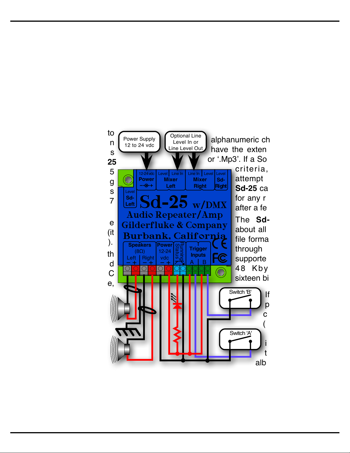
Speaker Outputs:
The Sd-25’s amplifier is a ‘Class-D’ design.
Its efficiency is near 90%. If you feed 50
Watts of 24 vdc into the Sd-25’s amplifier,
you will get almost 50 Watts into your
speakers. ‘Linear’ amplifiers have only about
20% efficiency. Fully 80% of the power you
put into them goes into the heatsink as
waste heat. A 50 Watt linear amplifier would
only feed 10 Watts of power into your
speakers, and 40 Watts into the heatsink.
This makes the Sd-25’s amplifier roughly
equivalent to what would be a 200 to 250
Watt linear amplifier!
If you are going to run your speakers at high
SPLs, you will need to select speakers that
can handle at least 125 to 150 Watts or
more of continuous power. Speakers
smaller than this may clip or be damaged if
run at too high an output power level from
the Sd-25.
The amplifier outputs from the Sd-25 can be
used with speakers of eight ohms (or higher)
impedance, or four ohms when bridged. As
with any amplifier, you can series/parallel a
number of speakers, so long as the
impedance remains within these limits.
In rare cases your speaker may clip out at
an unusually low level. This may be that the
protection circuitry inside the crossover is
confused by the digital output of the Sd-25’s
amplifier. If this is the case, we have a small
filter modules that can filter the high
frequency spikes the speaker receives.
The Sd-25’s amplifier is well protected from
short circuits and overheating. You can stick
a screwdriver right across the speaker
terminals. The amplifier will instantly turn off.
The Sd-25‘s amplifier will go back to work
an instant after a fault is removed.
If the speaker impedance is too low and you
are running at a high volume level, the
amplifier may start to cut out. If you hear
this, check the power supply voltage. If the
power supply voltage is dropping, you might
simply be drawing too much power for the
power supply and a larger supply may fix
your problem. If the power supply is OK, and
you can’t increase the speaker impedance,
then you might simply be asking too much of
the Sd-25’s amplifier, and need to turn down
the volume a tad.
If you wish to comply with FCC and CE
standards for radio frequency emissions, you
should use shielded speaker wires with the
Sd-25. The shield should be attached to a
good ‘Earth’ ground. If no ‘Earth’ ground is
available, then attach the shields to the
‘negative’ power supply terminal, which is
immediately adjacent to the speaker
terminals. This will not effect the sound
quality from the Sd-25, but will make the
FCC and CE folks happy. Shielded speaker
lines were used during all CE/FCC
certification testing.
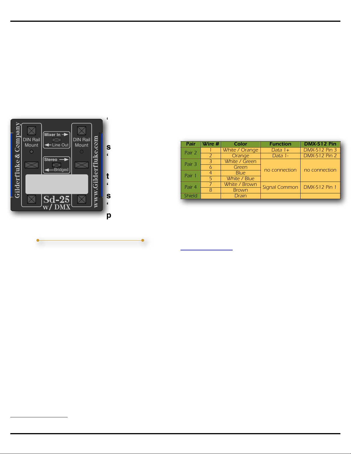
Bridged Amplifier:
If you need a mono output
with more ‘oomph’, then
amplifier in the Sd-25 can be
‘bridged’. Bridging will only
have an effect with lower
impedance speakers (4
ohms). You won’t hear a bit
of difference if you are Bridged Wiring
Left Right
Power
12-24
vdc
Speakers
(8Ω)
Gilderfluke & Co.• 205 South Flower Street • Burbank, California 91502 • 818/840-9484 • 800/776-5972 • fax 818/840-9485
Sd-25 w/DMX Manual • page 8 of 40 • © July 21, 2017 • Gilderfluke & Co. • DCM

using an 8 ohm speaker. The only audio
which is amplified comes from the ‘left’
sources (mixer and repeater). The wiring to
‘bridge’ the amplifier is a little different from
what you might be used to on a linear
amplifier. The speaker is wired in parallel to
both speaker outputs as shown in the
drawing, and the ‘Stereo/Bridged’ switch on
the bottom of the Sd-25 is moved to the
‘Bridged’ position.
Wiring the
speakers for a
‘Bridged’ output
without
throwing the
‘Stereo/Bridged’
switch to the
‘Bridged’
position can
damage the Sd-25’s amplifier.
DMX-512 Inputs:
If you are using the Sd-25 with any
Gilderfluke & Co. controller other than a
Br-miniBrick41, you will want to trigger and
control the Sd-25 via the DMX-512
connection. This has several advantages:
•Instant access to any of 255 SoundFiles stored on the Sd-25
•Normally uses just one DMX-512 address
•Does NOT use any of the controller’s digital outputs
•Your Sd-25s are Automatically configured & programmed by
Pc•MACs. You just put markers on the timeline in your shows
where you want SoundFiles to start, and Pc•MACs
automatically does all the work for you:
•Automatically programs in the sound triggers
•Automatically creates a folder for each Sd-25 used with
all the SoundFiles and settings in it. You just drag-n-drop
the contents of this folder onto your Sd card for the
Gilderfluke & Company
www.Gilderfluke.com
DIN Rail
Mount
DIN Rail
Mount
Sd-25
w/ DMX
Mixer In
Line Out
Bridged
Stereo
Sd-25s, and set the Sd-25’s DipSwitches as shown on
the text file Pc•MACs automatically creates for you.
•Supports virtually any number of Sd-25s, each with their
own SoundFiles and triggers.
•Optional volume control using a second DMX-512 channel
The DMX-512 connections are through two
RJ-45 connectors. These are the eight
position, eight conductor plugs typically used
for ethernet cables. They are also used for
DMX-512. The pinout of the DMX-512
connectors follows the USITT wiring
standards:
Pair
Wire #
Color
Function
DMX-512 Pin
Pair 2
1
White / Orange
Data 1+
DMX-512 Pin 3
2
Orange
Data 1-
DMX-512 Pin 2
Pair 3
3
White / Green
no connection
no connection
6
Green
Pair 1
4
Blue
5
White / Blue
Pair 4
7
White / Brown
Signal Common
DMX-512 Pin 1
8
Brown
Shield
Drain
The two DMX-512 connectors are wired in
parallel. Either one can be used as the
‘input’ or the ‘thru’. You can easily daisy
chain between multiple Sd-25’s,
v-HD-to-DMXs, Br-EFBs and other DMX-512
devices using standard (not crossover)
ethernet patch cables.
Whenever it is receiving valid DMX-512, the
Sd-25s will toggle its DMX-512 LED on each
packet received.
If the DMX-512 is coming from another piece
of GilderGear, it will automatically sense and
start using the GilderCheckSums. These
prevent the Sd-25s from triggering on any
corrupted DMX-512 packet.
If you plug the Sd-25’s Rs-232 port into a
computer and fire up GilderTerm (or any
other terminal program), it will display the
current DMX-512 mode, DMX-512 address,
if DMX-512 is being received and if
Gilderfluke & Co.• 205 South Flower Street • Burbank, California 91502 • 818/840-9484 • 800/776-5972 • fax 818/840-9485
Sd-25 w/DMX Manual • page 9 of 40 • © July 21, 2017 • Gilderfluke & Co. • DCM
1The Br-miniBrick4 is the only Gilderfluke & Co. controller that can’t transmit DMX-512

GilderCheckSums are being received in the
DMX-512.
Automatic DMX-512 Triggering:
If you are controlling your Sd-25 from
GilderGear, you will probably be letting
Pc•MACs automatically do all of the work for
you.
When you are creating your show, you need
to tell Pc•MACs about any Sd-25s w/DMX
you are using, just as you would with any
other GilderGear or 3rd party gear. This is
done on Pc•MACs Channels list.
1)!Open the
Channels List from
the Channels menu
(shortcut = F7).
Select the ‘Add
Device with
Channels’ command
from the Channels
M e n u , o r b y
right+Clicking in the
Channels List itself.
2)!Slide over to pick the Sd-25 w/DMX to
add to your show. Repeat this as needed, or
if you are adding
several Sd-25s
w/DMX, you can use
the ‘Add Multiple
Devices’ command
as a shortcut.
To add a drag-n-drop
Audio/Video trigger to a show,
open the OffLine Editing
1
2
Window.
3)!Right+Click at the time you would like the
SoundFile to start playing, anywhere on the
OffLine Editing Window (except on a
channel). A
contextual
menu will
appear.
Slide
down to
the bottom
and select the ‘New
Trigger’. This will give you
the option of adding:
a) String Trigger
b) Audio/Video Trigger
c) Comment
Select ‘Audio/Video Trigger’.
4)!If you have
more than
one Audio/
Video device
already
added to the
Channels List,
just pick the Sd-25 w/DMX you want to use
from the pulldown list.
5)!Click on this button to choose your
Audio/Video file.
6)!The default ‘name’ for the trigger is the
name of the Audio/Video file, but you can
change it if desired.
That’s really all you need to do!
You can have multiple drag-n-drop
Audio/Video triggers in each show, and
Pc•MACs will keep track of them for you,
only downloading the Audio/Video files you
have used. Pc•MACs will automatically add
an offset to compensate for any triggering
3
4
5
6
Gilderfluke & Co.• 205 South Flower Street • Burbank, California 91502 • 818/840-9484 • 800/776-5972 • fax 818/840-9485
Sd-25 w/DMX Manual • page 10 of 40 • © July 21, 2017 • Gilderfluke & Co. • DCM

delays when it ‘draws’ in the Audio/Video
triggers during the AutoDownload process. If
needed, you can adjust this using the ‘offset
frames’ dropdown on the Audio/Video trigger
setup dialog. While you are working in
Pc•MACs, you can also choose whether you
want to mute audio output from your
computer (normally unchecked), and if the
waveform is displayed on the OffLine
Window (normally checked).
If you hit ‘play’ on your computer, you will
hear the audio play from your computer’s
speakers. You can start and stop anywhere
in your show, and the sound will be in sync.
If you want your Audio/Video files to also
play back from your Sd-25s w/DMX while
you are programming from your PC, just do
a quick AutoDownload. Drag the contents of
the resulting drag-n-drop folder to a Sd card,
plug the Sd card into the player and set the
dipswitches as shown in the text file. Once
the files are on the players, Pc•MACs will be
able to trigger them too.
Manual DMX-512 Triggering:
SoundFiles are triggered by ‘bumping’ the
data sent to the DMX-512 address you have
set for the Sd-25. The bump should have no
ramping, as that could trigger other
SoundFiles as it ramps up and down.
With one through eight SoundFiles loaded
on the Sd-25, each individual bit triggers
each SoundFile. If you bump the channel to
a value of:
Decimal
Value
Hexadecima
l
Bit Number
SoundFile played
1
0x01
0
SoundFile #1
2
0x02
1
SoundFile #2
4
0x04
2
SoundFile #3
8
0x08
3
SoundFile #4
16
0x10
4
SoundFile #5
32
ox20
5
SoundFile #6
64
0x40
6
SoundFile #7
128
0x80
7
SoundFile #8
With between nine and 255 SoundFiles
loaded onto the Sd-25, You just ‘Bump’ the
DMX-512 address you have set for the
Sd-25 to the value of the SoundFile you
want to play. If you bump the channel to a
value of:
Decimal Bump
Value
Hexadecimal
Bump Value
SoundFile played
1
0x01
SoundFile #1
10
0x0A
SoundFile #10
100
0x64
SoundFile #100
255
0xFF
SoundFile #255
If you have set the DipSwitches to DMX-512
mode 2 (DipSwitch #11 =Off and DipSwitch
#12 = On), once you start a SoundFile
playing, you will not be able to start another
SoundFile until the first SoundFile has
finished. This is called ‘Unsteppable’ mode.
If you have set the DipSwitches to DMX-512
mode 3 (both DipSwitch #11 and DipSwitch
#12 = On), then the next consecutive
DMX-512 address after the address used for
selecting and playing the SoundFiles will be
used to control the volume of the audio
played from the Sd card. A 100% value will
give you full volume, limited by both the
volume control pots and any muting provided
by the trigger inputs (see next paragraph).
Serial and DMX-512 volume commands are
not saved to non-volatile memory.
When in any of the DMX-512 operating
modes, the two trigger inputs can be used to
fully mute (input ‘A’) or partially mute (-12 dB
on Input ‘B’) the audio from the Sd card. This
is equivalent to the non-DMX mode-3 with
the ramp speed set to the slowest rate.
The twelve position DipSwitch controls the
DMX-512 address and mode of operation for
the DMX-512 port on the Sd-25. The first
nine positions set the address, and the last
two switches control the DMX-512 mode. A
pen or any other pointy object can be used
Gilderfluke & Co.• 205 South Flower Street • Burbank, California 91502 • 818/840-9484 • 800/776-5972 • fax 818/840-9485
Sd-25 w/DMX Manual • page 11 of 40 • © July 21, 2017 • Gilderfluke & Co. • DCM

to flip the switches. Do not use a knife or
other sharp object, as it might damage the
switch.
Despite of what it may say on the switch,
Down is Off and Up is On.
DMX
Mode
Sw 1 -
Sw 9
Sw 10
Sw 11
Sw 12
Description
Non-D
MX
Mode &
Options
Off
=
Amp
on only
when
playing
On
=
Amp
always
on
Off
Off
Not Using DMX-512.
Select operating mode
& options on Sw 1-9
DMX
Mode 1
DMX
Address
On
Off
One DMX address
selects & plays
SoundFiles
DMX
Mode 2
DMX
Address
Off
On
Same as above, but
once playing,
SoundFiles are
Unsteppable
DMX
Mode 3
DMX
Address
On
On
1st addr. used to select
& play SoundFiles,
2nd controls volume
The DMX-512 Address is set using
DipSwitch positions #1 through #9
(down=Off, up = On).
DMX-512 addresses are either ‘One-Based’
(addresses run from 1 to 512) or ‘Zero-
Based’ (addresses run from 0 to 511).
Zero-based DMX-512 addressing was
originally used on all DMX-512 equipment.
Some users had trouble with the idea of
counting from ‘zero’, so one was added to
the zero-based DMX-512 addresses to make
them one-based. Most installations now use
one-based DMX-512 addresses.
Use the first column to find a One-Based
DMX-512 address. Use the second column
for Zero-Based DMX-512 addresses. Then
set DipSwitch positions one through nine as
shown in the chart at the end of this manual.
Trigger Inputs:
The two trigger inputs can be used with any
type of switch. This can be a pushbutton,
motion detector, IR beam, step mat, a digital
signal from a control
system, or anything
else that will give you
a ‘powered switch
closure’. The
trigger inputs
a r e n o n -
polarized
(they don’t care
which
termi nal is
posit ive or
negative) and
opto-isolated. You
must feed a DC voltage into them. Just
touching a pair of leads from a nine volt
transistor radio battery is a good test of the
inputs. As shown in the first illustration, you
can ‘borrow’ some of the power that is
running the Sd-25 using the adjacent
‘Power’ screw terminals, or use a separate
isolated supply (as
shown in the
second illustration).
The isolated power
supply can
be any DC
power
s u p p l y o r
battery, as
long as the
o u t p u t i s
between 5
and 24 vdc.
Because the inputs are not
polarity sensitive, you can wire the power
B
Right
Power
12-24
vdc A
Trigger
Inputs
Speakers
Running
Status
Switch 'B'
Switch 'A'
B
Left Right
Power
12-24
vdc A
Trigger
Inputs
Speakers
(8Ω)
Running
Status
Switch 'B'
Switch 'A'
Isolated
Power
Supply
Gilderfluke & Co.• 205 South Flower Street • Burbank, California 91502 • 818/840-9484 • 800/776-5972 • fax 818/840-9485
Sd-25 w/DMX Manual • page 12 of 40 • © July 21, 2017 • Gilderfluke & Co. • DCM

supply with either polarity. i.e.: You can’t get
it wrong.
The best test for your wiring are the green
‘Input’ LEDs, located adjacent to the inputs’
screw terminals. These LEDs are on the
isolated side of the inputs, so if the Sd-25 is
powered and you apply a voltage to an input,
the LED will light.
If these LEDs are ‘glowing’ even dimly when
off, that is an indication that an AC voltage is
being induced on the wires to your switches.
Either separate the switch wires from the AC
wires (this can include speaker lines), or add
a small resistor across the input terminals to
drain away this induced voltage.
Not surprisingly, all Gilderfluke &
Co. control systems are easy to
attach to an Sd-25. A
Br-miniBrick4 is shown because
it is the only piece of GilderGear
that doesn't have DMX-512
networking. We recommend
attaching all other GilderGear to
the Sd-25’s using the DMX-512
network.
On the Br-miniBrick4, the
common positive is run to one
side of both Sd-25 inputs, and
the control system outputs are
wired to the Sd-25 inputs.
Power Supply:
The Sd-25 will run on any voltage from 12
through 24 vdc. Size your power supply so it
will provide enough current for the volume
you are planning to run through your
speakers. The amplifier will put out more
power at 24 volts than it can at a lower
Br-MiniBrick4
Gilderfluke & Co.
Burbank, California
0
1
2
3
Record
Go
Data
Trigger
9-24
vdc
Outputs
Outputs
Triggering from a
Control System
A
Inputs
B
Sd-10
Sd-25 w/DMX
voltage. If using all 50 Watts of the amplifier
power, you will need to use a 24 volt supply
rated for at least 60 Watts. By its nature, the
Class-D amplifier can switch between
drawing nothing to drawing 50+ Watts
thousands of times per second. The power
supply must be able to do this without
dropping out. If you hear clipping, the
speakers or power supply may be
undersized for your application, or your
speakers may have an impedance below 8
ohms.
If you aren’t using the amplifier, the Sd-25
will run on as low as 7 volts. Below 12 volts
the amplifier is disabled.
The power supply can be attached through
either the 2.1 mm power jack, or the screw
terminals. They are wired in parallel.
Power Supply voltages higher than 24 vdc
can potentially damage the amplifier on the
Sd-25. The ESD protection diodes on the
power supply inputs are rated for 30 VDC
before they kick in.
Gilderfluke & Co.• 205 South Flower Street • Burbank, California 91502 • 818/840-9484 • 800/776-5972 • fax 818/840-9485
Sd-25 w/DMX Manual • page 13 of 40 • © July 21, 2017 • Gilderfluke & Co. • DCM

Volume Controls:
A pair of small trimpots on the Sd-25 are
used to set the maximum audio output level
from the Sd card. The operating modes
which ramp the audio up and down can
never exceed the level set by these pots.
An additional pair of pots is used to set the
levels for the ‘mixer’ inputs.
You can adjust these pots using a small
‘trimmer’ screwdriver. A suitable screwdriver
comes as part of the Sd-25/Starter Kit.
These trimpots are smaller than you. Do not
use a big screwdriver on them. Do not apply
too much force. They can be broken if you
strong-arm them!
Line Level
Input/Output
Sd Volume
Mixer Volume
IR Sensor
Window
Line Level Inputs and Outputs:
Two gold plated
‘RCA’ jacks are
available on
Sd-25s ( a s
shown in the
preceding photo).
A switch on the
bottom of the
case allows you
to switch these
jacks between a
line level output of the audio coming from the
Sd card, or a line level input that gets mixed
with the audio coming from the Sd card.
When the switch is set to the ‘Line Out’
position, the audio from the Sd Card is sent
to both the amplifier and the RCA jacks. Only
the audio going to the amplifier is routed
through the ‘Sd Level’ pots. The RCA
outputs will always be at full volume unless
the audio level is reduced in the DSP by a
serial volume command, DMX-512 volume
command, or full or half muting command
from the trigger inputs.
To use the line level outputs, just run a pair
of RCA cables to your amplifier (or amplified
speakers), just as you would if you were
connecting an iPod or CD player. The line
level outputs are robust enough to drive
headphones and small speakers directly.
When the switch is set to the ‘Line In’
position, line level audio signal from a Sd-10
or another Sd-25 audio repeater,
pre-amplified microphone or any other
line-level audio source can be plugged into
the two RCA jacks. Two ‘Mixer Level’
trimpots can be used to adjust the audio
levels of the mixer inputs. These inputs’
Gilderfluke & Company
www.Gilderfluke.com
DIN Rail
Mount
DIN Rail
Mount
Sd-25
w/ DMX
Mixer In
Line Out
Bridged
Stereo
Gilderfluke & Co.• 205 South Flower Street • Burbank, California 91502 • 818/840-9484 • 800/776-5972 • fax 818/840-9485
Sd-25 w/DMX Manual • page 14 of 40 • © July 21, 2017 • Gilderfluke & Co. • DCM

levels are not effected by a serial volume
command, DMX-512 volume command, or
full or half muting command from the trigger
inputs.
In this example, a pre-amplified (or line level)
microphone is fed into the mixer inputs of the
Sd-25. The ‘Push to Talk’ button on the
microphone is fed into the ‘b’ input of the
Sd-25. The Sd-25 is configured to ‘duck’ the
audio from Sd the card to a lower level when
it sees a closure on the ‘b’ input. When the
microphone button is pressed, the Sd-25
ramps the prerecorded audio down to a
lower level, and the microphone is used to
make an announcement. When the ‘PTT’
button is released, the prerecorded audio
ramps back up to the normal playback level.
12-24vdc
Power
Level
Sd-
Left
Line InLevel Line In Level Level
Sd-
Right
Mixer
Right
Mixer
Left
Audio Repeater/Amp
Gilderfluke & Company
Burbank, California
Sd-25 w/DMX
B
Left Right
Power
12-24
vdc A
Trigger
Inputs
Speakers
(8Ω)
Running
Status
Pre-Amp
'PTT' Switch
PreAmp
Modulation LEDs:
The two ‘modulation’ LEDs, which are
located in front of the speaker screw
terminals, blink to show audio as it is being
reproduced. They pick up the audio signal
coming from the repeater before the two
volume control pots, so they are not affected
by adjusting these pots or by the auxiliary
‘mixer inputs. Reducing the audio level
through one of the ‘ramping’ functions will
reduce the intensity of these LEDs. Audio at
too low a level will cause these LEDs to
completely extinguish. Normalize your audio
before loading it on the Sd-25 so that it is
near 100% modulation.
Sometimes additional safety system
assurance above and beyond monitoring the
‘Status’ Relay Output output is needed to
confirm that the Sd-25 is actually playing. An
external solid state relay or optoisolator can
be attached in place of these LEDs. The
safety system can then monitor this to
confirm that an audio signal is indeed being
generated. Contact Gilderfluke & Company
for more information on this sort of
application.
‘Status’ Relay Output:
A single solid state
r e l a y o u t p u t i s
available for remote
monitoring of the
Sd-25. It is ‘on’ only
while the Sd-25 i s
playing a triggered or
‘foreground’ SoundFile. It
is not active while stopped
or when playing a
‘background’ looping
SoundFile. It can be
used to control
ducking mixers, relays, or
whatever you need.
This output is a solid state relay output,
which is rated for up to 250ma at up to 24
Volts of AC or DC. Like the trigger inputs,
this output is not polarity sensitive. Unless
whatever you are controlling is polarity
sensitive (like the input to a larger solid state
relay or an LED, as shown in the
illustrations), you can ignore power supply
Right
Power
12-24
vdc A
Trigger
Inputs
Speakers
Running
Status
B
Right
Power
12-24
vdc A
Trigger
Inputs
Running
Status
Isolated
Power
Supply
Gilderfluke & Co.• 205 South Flower Street • Burbank, California 91502 • 818/840-9484 • 800/776-5972 • fax 818/840-9485
Sd-25 w/DMX Manual • page 15 of 40 • © July 21, 2017 • Gilderfluke & Co. • DCM

polarity and wire it up either way. You can
power the ‘Status’ Relay Output from the
adjacent Power Supply screw terminals (as
shown at left), or use an isolated AC or DC
power supply (as shown at the right).
To turn on a light, motor, or other electrical
device while a triggered or foreground
SoundFile is playing, just wire a solid state
relay to the ‘Status’ Relay Output. Then wire
the light, motor, or whatever you are
controlling to this relay. This can be used in a
museum, trade show, Point Of Sale (POS)
and other applications where all you need to
do is turn ‘on’ a light or other device while
your SoundFile is playing.
HINT: If you need the ‘Status’ Relay Output
to turn on after the Sd-25 is triggered, but
before your SoundFile starts playing, or stay
on for a bit after the SoundFile ends, just
pad out your SoundFile with silence. Sd-25
turns on this output when a foreground
sound is playing. It doesn’t care if you
happen to be playing ‘silence’. It will turn on
the output just the same.
Another application for the ‘Status’ Relay
Output is when you need a background
audio SoundFile to continue playing when a
triggered foreground SoundFile is also
playing, the BGM SoundFile can be played
from a Sd-10 or another Sd-25 which feeds
its audio into the ‘mixer’ inputs of the first
Sd-25.
When the Sd-25 plays a triggered SoundFile
or a timed announcement (if using modes
16, 17 or StoreCaster mode) the ‘Status’
Relay Output will go active. This is wired into
an input on the Sd-10 which has been
configured to partially duck, or fully mute its
audio output. In this way, the Sd-10 will duck
(or mute) the BGM SoundFile (without
stopping it) while the foreground SoundFile
plays.
‘Background’ looping SoundFiles, like those
in modes 16 and 17 will not turn on the
‘Status’ Relay Output. When in these modes,
the ‘Status’ output will only be turned on
when a triggered SoundFile is playing. In
StoreCaster mode, the ‘Status’ Relay Output
will only be turned on when playing
SoundFile #1.
In a safety related application, such as a fire
or emergency annunciator system, the
safety system can monitor this output to
confirm the Sd-25 is receiving commands
and playing SoundFiles. For absolute surety,
you can monitor that this output goes active
when a SoundFile is triggered, and goes
inactive at the end of the SoundFile.
Status Output LED:
The LED which is next to the ‘Status’ relay
output does not reflect the current state of
the Status Output Relay. Instead, it flashes
to show accesses to the Sd flash card by the
Sd-25.
This LED will flicker when an Sd-25 boots,
12-24vdc
Power
Level
Sd-
Left
Line InLevel Line In Level Level
Sd-
Right
Mixer
Right
Mixer
Left
Audio Repeater/Amp
Gilderfluke & Company
Burbank, California
Sd-25 w/DMX
B
Left Right
Power
12-24
vdc A
Trigger
Inputs
Speakers
(8Ω)
Running
Status
Audio
Repeater
Line Out
A
Inputs
Sd-10
9-24
vdc
B
Power
Right
Left
9-24 vdc
Burbank, California
Gilderfluke & Co.
Gilderfluke & Co.• 205 South Flower Street • Burbank, California 91502 • 818/840-9484 • 800/776-5972 • fax 818/840-9485
Sd-25 w/DMX Manual • page 16 of 40 • © July 21, 2017 • Gilderfluke & Co. • DCM

as it counts each SoundFile on the card2.
When not playing, it will be very dim. While
playing, it will flicker at a high rate of speed.
The faster the flicker, the higher your
SoundFile’s bit rate.
RS-232 Serial Port:
An RS-232 serial port is built in to every
Sd-25. On the earlier versions of the Sd-25,
the serial port was available only as an
option (part #Sd-RS/232).
The serial port on a Sd-25 runs at a fixed
rate of 9600 baud, n, 8, 1.
Adapters to attach this port to a PC or Mac
are available from Gilderfluke & Company as
(as part numbers C-USB-RS232 or
USB-RS232/422). It can also be controlled
from a Gilderfluke & Co. Br-SDC/09 (a null
modem cable must be used to flip pins #2
and #3 when used with a Br-SDC/09).
The RS-232 serial port uses a ⅛” (3.5mm)
stereo plug. The pinout to connect this to a
standard DE-09 connector as found on a PC
or our serial adapters is as shown:
We offer a ready-made cable as our part
number Mp3-50/CBL.
When the Sd-25 boots or a Sd card is
inserted, the Sd-25 will list all the SoundFiles
Rxd
Txd
gnd
IBM AT
Serial
1
2
3
4
5
6
7
8
9
1
3
2
3.5mm Stereo
(ring)
(tip)
(sleeve)
that are found, as well as the order after
sorting them alphanumerically:
When any SoundFile is played, the
configuration settings and the name and info
about the SoundFile are displayed through
the serial port. The Sd-25 then reports the
SoundFile time as it plays.
If set for DMX-512 input, the status report
will show which DMX-512 mode the player is
in, the DMX-512 address, if DMX-512 is
being received, and if the DMX-512 packets
contain GilderCheckSums.
Gilderfluke & Co. Sd-25w/DMX v1.28 copyright 2014 DCM
a=C, b=C, DipSw=_2______9___
mode=02, Volume Level=__0, Sd Card w/__0 SoundFiles
xxx: HERO____.MP3
SoundFileTime=____0
_SoundFiles__|__#__|_pos.
CLOCKS__.MP3 | __1 | ___0
HERO____.MP3 | __2 | ___1
LABAMBA_.MP3 | __3 | ___2
ROAM____.MP3 | __4 | ___3
SMOOTH__.MP3 | __5 | ___4
FARAWA~1.MP3 | __6 | ___5
BIGLOVE_.MP3 | __7 | ___6
CLDASICE.MP3 | __8 | ___7
sorted list...
__1 BIGLOVE_.MP3
__2 CLDASICE.MP3
__3 CLOCKS__.MP3
__4 FARAWA~1.MP3
__5 HERO____.MP3
__6 LABAMBA_.MP3
__7 ROAM____.MP3
__8 SMOOTH__.MP3
Gilderfluke & Co. Sd-25w/DMX v1.28 copyright 2014 DCM
a=O, b=O, DipSw=_2______9___
mode=02, Volume Level=255, Amp=ON, Sd Card w/__8 SoundFiles
__5 HERO____.MP3
SoundFileTime=____8
Gilderfluke & Co. Sd-25w/DMX (DEBUG!) v1.28 copyright 2014 DCM
a=O, b=O, DipSw=_2________B_
mode=is DMX-1 @ address: __2 DMX is active w/High CS
Volume Level=255, Amp=ON, Sd Card w/__8 SoundFiles
__5 HERO____.MP3
SoundFileTime=__103
Gilderfluke & Co.• 205 South Flower Street • Burbank, California 91502 • 818/840-9484 • 800/776-5972 • fax 818/840-9485
Sd-25 w/DMX Manual • page 17 of 40 • © July 21, 2017 • Gilderfluke & Co. • DCM
2The speed at which the Sd-25 counts the SoundFiles is perhaps the best indication of how ‘fast’ a SD flash card is. Fast cards will count up to ten SoundFiles
each second. Slower cards may only count one SoundFile per second.

Using the Serial Port to Select
and Play SoundFiles:
To select and play a SoundFile through the
serial port, send the Sd-25 an ASCII ‘p’
character (‘p’ is short for ‘play’), followed by
a two digit ASCII Hex number of the
SoundFile you want to be played. Example:
To play SoundFile 1, send ‘p01’. To play
SoundFile 5, send ‘p05’. For SoundFile 25,
send ‘p19’ (the value ’19’ is the hexadecimal
equivalent of the decimal number ’25’).
Using the Serial Port to Adjust
Audio Playback Levels:
To set the ‘normal’ audio playback level for
the Sd card through the serial port, send the
Sd-25 an ASCII <Control>+’V’ character
(0x16), followed by a two digit ASCII
hexadecimal number of the level you want to
use. Valid levels are ’00’ to ‘FF’. Example: to
set playback level to 0x80, send
‘<0x16>’,’80’.
You do this by holding down the <control>
key and then pressing the letter ‘v’. Release
the <control> key and press ‘8’ and then ‘0’
to send the value for the audio level.
The volume control through the serial port is
highly logarithmic. Once set, the Sd-25 will
scale all the ‘mute’ and ‘duck’ functions to
the value you have set as the ‘normal’
playback level. Serial and DMX-512 volume
commands are not saved to non-volatile
memory.
InfraRed (IR) Port:
An IR port is built
into every Sd-25.
You can see the
window on the left
side of the case for
the IR sensor.
On the earlier versions of the
Sd-25, the IR port was available
only as an option (part #Sd-IR/Rx). The IR
receiver was used solely in one of the two IR
modes (either mode 1A or 1B) to trigger
sounds from an Ir-Tx. On the Sd-25 it can
also be used with an Apple IR remote control
for triggering, testing and volume control.
Whenever the Sd-25 receives an IR signal,
the DMX-512 LED will flash.
The IR receiver on the Sd-25 has a fairly
wide reception angle. In some applications
you may need to ‘snorkel’ the receiver and/or
transmitter to narrow the beam to suit your
application. In outdoor applications you may
need to do this just to keep sunlight from
hitting the sensor directly and temporarily
overwhelming it.
IR Port in Modes 1A or 1B:
These modes are typically used to trigger
sound onboard a train, monorail, hay wagon,
bus, or other vehicle.
These two modes are used with Ir-Tx
transmitters. Each Ir-Tx is set to send out a
continuous request for a specific SoundFile.
When the IR receiver comes into range of
the Ir-Tx, it will play the requested
SoundFile.
IR Sensor
Window
Gilderfluke & Co.• 205 South Flower Street • Burbank, California 91502 • 818/840-9484 • 800/776-5972 • fax 818/840-9485
Sd-25 w/DMX Manual • page 18 of 40 • © July 21, 2017 • Gilderfluke & Co. • DCM

In some cases, the
Sd-25s are mounted
next to the path of
the vehicle. An
Ir-Tx is mounted
on each vehicle,
and SoundFiles
are triggered from
stationary speakers as each
of the vehicles pass them.
In most applications, the Sd-25 is mounted
where the IR sensor can see out the left or
right side of the vehicle. As the vehicle
passes Ir-Txsalong its route (and on the
same side of the vehicle as the Sd-25’s IR
port is facing), the desired SoundFiles are
played through on-board speakers.
Even if the route of the vehicle is ‘random’,
the proper SoundFile will always be
triggered as it passes each Ir-Tx transmitter.
You can even have different Ir-Txson each
side of a roadway, transmitting requests for
different SoundFiles. One set of SoundFiles
will be triggered when the vehicle goes in
one direction, and a completely different set
of SoundFiles will be triggered when the
vehicle travels in the opposite direction.
HINT: if you have different SoundFiles that
are played at different times (example: One
set of SoundFiles that plays during the
daytime, and another set that plays during
the night), you can used two sets of Ir-Tx
transmitters to select which plays. Load the
Sd-25s with both sets of SoundFiles. Power
up one set of Ir-Txs, and only the
SoundFiles it requests are played. Swap
power to the other set of Ir-Txs, and then
only the second set of SoundFiles will be
played. One major theme park does a
‘holiday’ redecoration of their major shows.
They used this technique to change their
audio systems between the ‘normal’ show
and the ‘holiday’ show with the flick of a
single switch.
IR Port with Apple IR Remote:
When not set to either
o f t h e I R m o d e s
(modes 1A or 1B), or
set to listen to
DMX-512, the IR port
on the Sd-25 can be
used with an Apple IR
remote control. These
can be used for testing
and adjusting audio
levels, or as the permanent
method of triggering SoundFiles
from a handheld button by an
actor or docent in an attraction or
museum.
The Apple IR remotes have been
manufactured in two different models: The
older all-plastic (right) and newer
all-aluminum (left). Either one will work with
the Sd-25. The aluminum remote has one
more button than the plastic model, but other
than that, they are operationally identical. If
you don’t already have a drawer full of Apple
remotes laying around, you can purchase a
new All-Aluminum remote for $19 from
A p p l e . I t i s t h e i r p r o d u c t n u m b e r
MC377LL/A. There are also lots of covers
and cozies available for the Apple Remotes
from third party vendors.
The buttons are used as follows on the
Apple IR Remotes:
Apple
Plastic IR
Remote
Apple
Aluminum
IR Remote
Function
+
Up
Volume Up
-
Down
Volume Down
Left
Left
Select & Play ‘Previous’ SoundFile
Gilderfluke & Co.• 205 South Flower Street • Burbank, California 91502 • 818/840-9484 • 800/776-5972 • fax 818/840-9485
Sd-25 w/DMX Manual • page 19 of 40 • © July 21, 2017 • Gilderfluke & Co. • DCM

Apple
Plastic IR
Remote
Apple
Aluminum
IR Remote
Function
Right
Right
Select & Play ‘Next’ SoundFile
Menu
Menu
Player Status Updated on RS-232 Port
Center
Pause/Play
Play/Pause/Continue
Center
Play/Stop
A few seconds after adjusting the volume
level through Apple IR Remote, the volume
setting will be saved into non-volatile
memory in the Sd-25. If you power the unit
down, the next time you power it up it will
return to playing at this preset level. This is
useful for adjusting the audio levels in
applications where the Sd-25 is mounted in
a difficult-to-reach location.
If you have the RS-232 port connected to
your computer, it will display all IR
commands as they are received.
HINT: If mounting the Sd-25 in a
hard-to-reach location, use the pots to set
the ‘worst case’ maximum volume for the
speakers as it is being hung. When you
climb down off the ladder, then use the Apple
remote to set the final audio levels.
Sd-25 Installation:
The Sd-25 can be mounted using two
screws on 2-1/4” centers; 2-3/4” Augat
‘Snap-Track’ (which itself can be DIN rail
mounted); using DIN rail adapters; or just
Velcro’d down. In many applications, the
Sd-25 can be attached on (or in) the
speakers it is feeding. The Sd-25 must not
be mounted where it might get wet, or suffer
from extremes of temperature.
The optional DIN rail mounts just snap onto
the back of the Sd-25. Once they are
snapped on, they are wicked hard to get
back off.
The Sd-25 has two 0.156” (4mm) diameter
mounting holes. You can use these if you are
just screwing the unit down:
Gilderfluke & Co.• 205 South Flower Street • Burbank, California 91502 • 818/840-9484 • 800/776-5972 • fax 818/840-9485
Sd-25 w/DMX Manual • page 20 of 40 • © July 21, 2017 • Gilderfluke & Co. • DCM
Other manuals for Sd-25
1
Table of contents