Gill GMX100 User manual

User Manual
For Compact Weather Stations
Document Number: 1957-PS-021 Issue 3 applies to units with firmware 2669 V2.XX.XX and
Serial Numbers 1801XXXX onwards.
Gill Instruments Limited
SaltmarshPark, 67 Gosport Street, Lymington,
Hampshire, SO41 9EG, UK
Tel:+44 1590 613500, Fax: +44 1590 613555
Email: anem@gillinstruments.com Website: www.gillinstruments.com
GM240
GMX541
GMX550
GMX600
GMX551
GMX531
GMX500
GMX300
GMX200
GMX100
GMX301
GMX400
GMX501
GMX101

Gill Instruments Ltd
_____________________________________________________________________________________________________________
__________________________________________________________________________________________________
MaxiMet Page 2 Issue 3
Doc. No. 1957-PS-021 May 2018
Contents
1. FOREWORD ...............................................................................................................6
2. INTRODUCTION..........................................................................................................6
2.1. MaxiMet Part Numbers and Parameters........................................................... 6
2.1.1 MaxiMet Order Part Numbers (2669 V2.XX.XX Firmware) .......................6
2.1.2 Summary of MaxiMet Sensors and Derived Parameters...........................7
2.1.3 Wind Speed and Direction Sensor (GMX200, GMX240, GMX500, GMX501,
GMX531, GMX541, GMX550, GMX551 and GMX600).................................................8
2.1.4 Solar Radiation Shield (GMX300, GMX301, GMX400, GMX500, GMX501,
GMX531, GMX541, GMX550, GMX551 and GMX600).................................................8
2.1.5 Barometric Pressure (GMX300, GMX301, GMX400, GMX500, GMX501,
GMX531, GMX541, GMX550, GMX551 and GMX600).................................................9
2.1.6 Temperature, Relative Humidity and Dewpoint (GMX300, GMX301,
GMX400, GMX500, GMX501, GMX531, GMX541, GMX550, GMX551 and GMX600)..9
2.1.7 Rain (GMX100, GMX240, GMX400, GMX541, GMX600 (and Gill Spare Part
1957-PK-073)) .............................................................................................................9
2.1.8 Rain (GMX531)........................................................................................9
2.1.9 Rain (GMX550 and GMX551)..................................................................9
2.1.10 Compass (GMX200, GMX240, GMX500, GMX501, GMX531, GMX541,
GMX550, GMX551 and GMX600)..............................................................................10
2.1.11 Compass Declination.............................................................................10
2.1.12 Solar (GMX101, GMX301, GMX501, GMX531, GMX541 and GMX551).10
2.1.13 GPS Option (GMX200, GMX240, GMX500, GMX531, GMX541, GMX550,
GMX551 and GMX600)..............................................................................................10
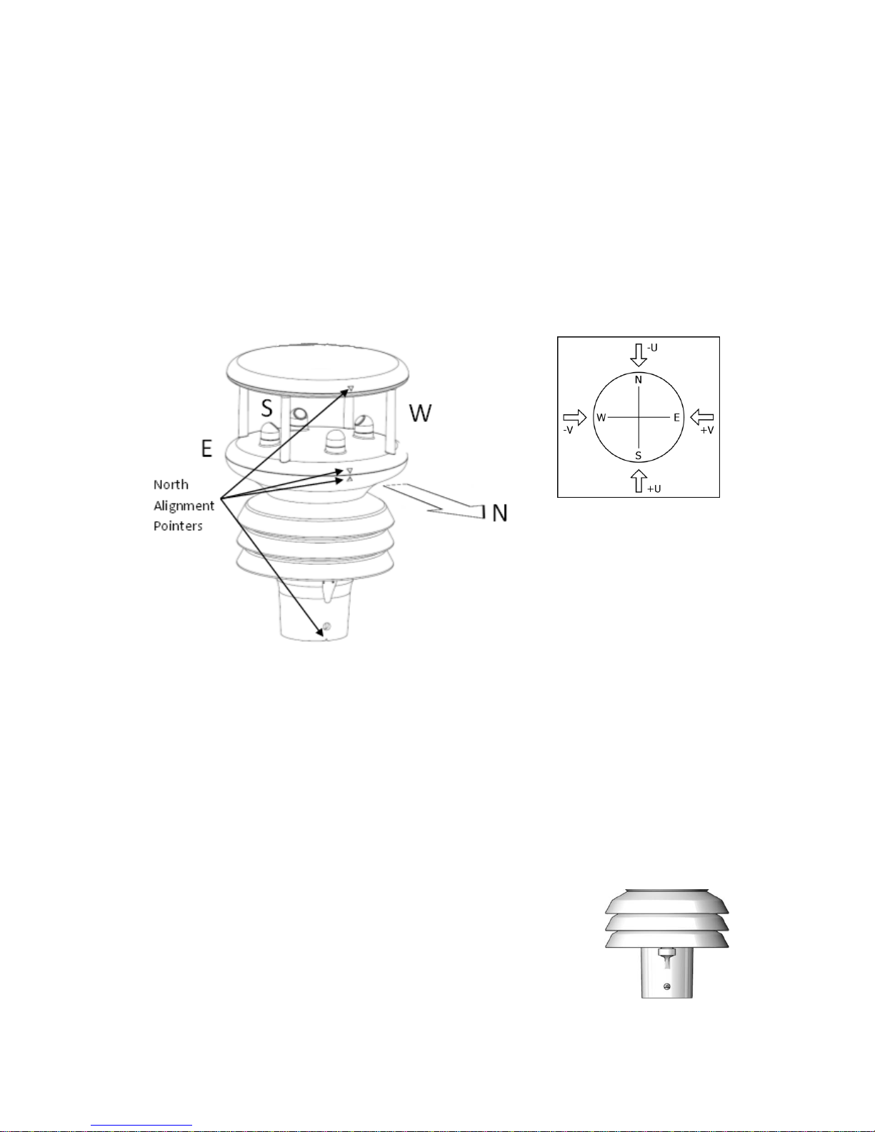
2.1.14 Inclinometer (All MaxiMet Models, diagram illustrates a GMX550)..........11
3. TECHNICAL SPECIFICATION..................................................................................12
4. PRE-INSTALLATION ................................................................................................17
4.1. Equipment supplied........................................................................................ 17
4.1.2 Optional Extras/Spares:.........................................................................17
4.2. Connector and Cable Assembly...................................................................... 17
4.3. Cabling ...........................................................................................................20
4.3.1 Cable Type............................................................................................20
4.3.2 Cable Length.........................................................................................20
4.4. Connections.................................................................................................... 21
4.4.1 View of the MaxiMet Connector looking down at the Cable Side.............21
4.4.2 9-Way Connector and Cable Connections..............................................21
4.5. Power supplies............................................................................................... 22
4.5.1 MaxiMet Units........................................................................................22
4.6. Connecting to a PC using RS232 (default setting)..........................................22
4.7. Connecting to a PC using RS422 (Not a default setting).................................23
4.8. Using RS485 (not a default setting)................................................................ 23
4.9. Using SDI-12 (2 wire network, not a default setting)........................................24

Gill Instruments Ltd
_____________________________________________________________________________________________________________
__________________________________________________________________________________________________
MaxiMet Page 3 Issue 3
Doc. No. 1957-PS-021 May 2018
4.10. Using the MaxiMet GMX531 with a Supplied Kalyx Rain Gauge or
GMX550/GMX551 (user supplies a Rain Gauge) .......................................................24
4.11. Using the MaxiMet GMX541 with supplied Gill Solid State Rain Gauge.......... 26
4.12. Set-Up Requirements .....................................................................................27
4.12.1 Host System..........................................................................................27
4.12.2 Software................................................................................................27
4.12.3 Bench System Test................................................................................27
4.13. Packaging.......................................................................................................27
5. INSTALLATION.........................................................................................................28
5.1. General Installation Guidelines.......................................................................28
5.1.1 Interference...........................................................................................28
5.1.2 Wind......................................................................................................28
5.1.3 Compass...............................................................................................29
5.1.4 GPS......................................................................................................29
5.1.5 Solar......................................................................................................29
5.1.6 Tilt.........................................................................................................29
5.1.7 Rain ......................................................................................................30
5.1.8 General Alignment.................................................................................32
5.1.9 Mounting Tube e.g. Gill Part 1405-30-056..............................................32
5.1.10 Mounting Bracket e.g. Gill Part 1771-PK-115.........................................33
5.1.11 Dimensions (in mm)...............................................................................34
6. CONFIGURING WITH METSET.................................................................................38
6.1. MaxiMet Default Configurations...................................................................... 38
6.2. Configuring MaxiMet with MetSet....................................................................55
6.2.1 Opening MetSet.....................................................................................55
6.2.2 MetSet Editing Screen...........................................................................57
6.2.3 MetSet Online Settings..........................................................................58
6.2.4 MetSet Editing Pages............................................................................58
6.3. Polled Mode.................................................................................................... 69
6.3.1 Configuration for Polled Mode (MaxiMet Set for Power Mode 0).............69
6.3.2 Data Retrieval in Polled Mode (MaxiMet Set for Power Mode 0).............69
6.4. Configuring MaxiMet for SDI-12...................................................................... 70
6.4.1 SDI-12 Units of Measure........................................................................70
6.4.2 SDI-12 Commands................................................................................71
6.4.3 SDI-12 Commands with CRC ................................................................73
6.5. Configuring MaxiMet for Modbus....................................................................76
6.5.1 MaxiMet Supported Modbus Specification..............................................76
6.6. Configuring MaxiMet for NMEA 0183 Output..................................................88
6.6.1 GMX100 NMEA Output String................................................................88
6.6.2 GMX101 NMEA Output String................................................................89
6.6.3 GMX200 NMEA Output String................................................................90
6.6.4 GMX240 NMEA Output String................................................................91
6.6.5 GMX300 NMEA Output String................................................................93

Gill Instruments Ltd
_____________________________________________________________________________________________________________
__________________________________________________________________________________________________
MaxiMet Page 4 Issue 3
Doc. No. 1957-PS-021 May 2018
6.6.6 GMX301 NMEA Output String................................................................94
6.6.7 GMX400 NMEA Output String................................................................95
6.6.8 GMX500 NMEA Output String................................................................96
6.6.9 GMX501 NMEA output String................................................................98
6.6.10 GMX531, GMX541 and GMX551 NMEA Output String ........................101
6.6.11 GMX550 and GMX600 NMEA Output String........................................103
6.7. Safe Mode.................................................................................................... 106
6.7.1 Summary.............................................................................................106
6.7.2 Safe Mode Method 1...........................................................................106
6.7.3 Safe Mode Method 2...........................................................................109
6.8. Using a Terminal Program to run MaxiMet Check Tilt Function..................... 110
6.9. Using a Terminal Program to Set MaxiMet Date and Time ........................... 111
7. VIEWING MAXIMET DATA STRING .......................................................................112
7.1. Use MetSet to View the MaxiMet Data String ............................................... 112
7.2. Using Gill MetView Software to View the MaxiMet Data String ..................... 113
7.2.1 Opening MetView.....................................................................................113
7.2.2 Scanning for Devices................................................................................114
7.2.3 The MetView Console...............................................................................115
7.2.4 MetView Console Display Options............................................................116
7.2.5 MetView Gauge Ranges and Graphs........................................................117
7.2.6 Data Logging............................................................................................119
7.3. Use a Terminal Program to View the MaxiMet Data String ........................... 120
8. MAINTENANCE & FAULT-FINDING.......................................................................123
8.1. Cleaning and Handling.................................................................................. 123
8.2. Servicing....................................................................................................... 123
8.2.1 Precipitation Sensor.............................................................................123
8.2.2 Solar Sensor........................................................................................126
8.2.3 Compass/GPS Modules.......................................................................126
8.2.4 Wind Sensor (WindSonic)....................................................................126
8.2.5 Barometer ...........................................................................................126
8.2.6 UV Shield (MetSpec)...........................................................................126
8.2.7 Temperature, Humidity and Dewpoint..................................................127
8.2.8 GMX531/GMX541/GMX550/GMX551 Side Connector.........................127
8.2.9 Calibration...........................................................................................127
8.3. Fault-finding.................................................................................................. 127
8.4. Safe Mode.................................................................................................... 128
8.5. Bench Test ................................................................................................... 128
8.6. Returning Units............................................................................................. 129
8.7. Guarantee..................................................................................................... 129
9. APPENDICES..........................................................................................................130
9.1. MaxiMet Output Parameters selectable using MetSet Software.................... 130

Gill Instruments Ltd
_____________________________________________________________________________________________________________
__________________________________________________________________________________________________
MaxiMet Page 5 Issue 3
Doc. No. 1957-PS-021 May 2018
9.2. Glossary & Abbreviations.............................................................................. 143
9.3. Electrical Conformity..................................................................................... 144

Gill Instruments Ltd
_____________________________________________________________________________________________________________
__________________________________________________________________________________________________
MaxiMet Page 6 Issue 3
Doc. No. 1957-PS-021 May 2018
1. FOREWORD
Thank you for purchasing the MaxiMet manufactured by Gill Instruments Ltd.
To achieve optimum performance we recommend that youread the whole of this manual before
proceeding with use.
Gill products are in continuous development and therefore specificationsmay be subject to change and
design improvements without prior notice.
The information contained in this manual remains the property of Gill Instruments andmust not be copied
or reproduced for commercial gain.
2. INTRODUCTION
The Gill MaxiMet sensor units are very robust with no moving parts. The sensor units, output rate and
formats are all user selectable.
The MaxiMet can be used in conjunction with a PC, data logger or other device.
The MaxiMet combines all the instrument data into a single data string. This may be configured for digital
ASCII RS232/RS422/RS485 (2 wire point to point only),digital Modbus RTU/ASCII, NMEA andSDI-12
outputs.
2.1. MaxiMet Part Numbers and Parameters
2.1.1 MaxiMet Order Part Numbers (2669 V2.XX.XX Firmware)
NOTE: For information within the part structure:-
1957-XXX-XX-XXX X– A number greater than 0identifiesthe unit to havea Solar Sensor fitted.
1957-05X-XX-XXX X - A number greater than 0 identifies the unit to have an external rain gauge input.
PROJECTCODE
1957 - 0 X X X - X X - X X X
MaxiMet GPS TBA TBA
0 1 0 0 6 0 0=NoGPS 0 0
0 1 0 1 1=GPS
0 2 0 0
0 2 4 0
0 3 0 0
0 3 0 1
0 4 0 0
0 5 0 0
0 5 0 1
0 5 3 1
0 5 4 1
0 5 5 0
0 5 5 1
0 6 0 0
OPTIONSMODELNUMBER WIND SPEED
Range m/s
GMX Model Number

Gill Instruments Ltd
_____________________________________________________________________________________________________________
__________________________________________________________________________________________________
MaxiMet Page 7 Issue 3
Doc. No. 1957-PS-021 May 2018
2.1.2 Summary of MaxiMet Sensors and Derived Parameters
(See Appendices, Para 9.1 for more details).
GMX Sensor Parameter 100 101 300 301 400 200 240 500 501 531 541 550 551 600
Wind Speed, Relative
Wind Direction, Relative
Compass, Heading
Temperature, Air
Humidity, Relative
Barometric Pressure
Rain/Precipitation (External Gauge)
Solar Radiation
GPS (option) Opt Opt Opt Opt Opt Opt Opt Opt Opt
GMX Derived Parameter 100 101 300 301 400 200 240 500 501 531 541 550 551 600
Average Speed (WMO)
Average Direction (WMO)
Average Corrected Direction
(WMO)
Corrected Direction
Gust Direction (WMO)
Gust Speed (WMO)
Status (Sensors)
Wind Status
Dewpoint
Absolute Humidity
Pressure at Sea Level
Pressure at Station
Precipitation Intensity
Precipitation Total
Precipitation Status
Wind Chill
Heat Index
Air Density
Wet Bulb Temperature
Solar (sunshine) Hours
Twilight
Sunrise
Solar Noon
Sunset
Position of the Sun
Angle of Tilt
Node Letter
Volts (Supply)
Time (and Date)
Corrected Speed GPS Opt GPS Opt GPS Opt GPS Opt GPS Opt GPS Opt GPS Opt GPS Opt GPS Opt
Average Corrected Speed (WMO) GPS Opt GPS Opt GPS Opt GPS Opt GPS Opt GPS Opt GPS Opt
GPS Opt GPS Opt
Corrected Gust Speed GPS Opt GPS Opt GPS Opt GPS Opt GPS Opt GPS Opt GPS Opt
GPS Opt GPS Opt
Corrected Gust Direction GPS Opt GPS Opt GPS Opt GPS Opt GPS Opt GPS Opt GPS Opt
GPS Opt GPS Opt
GPS Location (Longitude/latitude) GPS Opt GPS Opt GPS Opt GPS Opt GPS Opt GPS Opt GPS Opt
GPS Opt GPS Opt
GPS Heading GPS Opt GPS Opt GPS Opt GPS Opt GPS Opt GPS Opt GPS Opt
GPS Opt GPS Opt
GPS Speed GPS Opt GPS Opt GPS Opt GPS Opt GPS Opt GPS Opt GPS Opt
GPS Opt GPS Opt
GPS Status GPS Opt GPS Opt GPS Opt GPS Opt GPS Opt GPS Opt GPS Opt
GPS Opt GPS Opt

Gill Instruments Ltd
_____________________________________________________________________________________________________________
__________________________________________________________________________________________________
MaxiMet Page 8 Issue 3
Doc. No. 1957-PS-021 May 2018
2.1.3 Wind Speed and Direction Sensor (GMX200, GMX240, GMX500, GMX501,
GMX531, GMX541, GMX550, GMX551 and GMX600)
The MaxiMet uses theGill WindSonicwind speed and direction sensor. The WindSonicmeasures the times
taken foran ultrasonic pulse ofsound totravel from the north (N) transducer to the south (S)transducer,
and compares it with the time for a pulse to travel from S to N transducer. Likewise times are compared
between west (W) and east (E), andE and W transducer.
If, for example, a north wind is blowing, then the time taken for the pulse to travel from N to S will be
faster than from Sto N,whereasthe W toE and Eto W times will be the same. Thewind speed and
direction can then be calculated from the differences in the times of flight on each axis. This calculation is
independentof factors suchas temperature.
MaxiMet can output the following wind readings dependingon use ofa Compassor GPS:
Relative wind – wind speed and/or direction, uncorrected, but relative to the north marker, which
may not be facing north.
Correctedwind – with the aid of the CompassMagnetic North corrected wind directioncan be
output.
True wind – wind speed and/or direction information corrected by GPS for any direction
misalignment of the north marker and/or for any motion of the station. (E.g. vehicle or vessel).
2.1.4 Solar Radiation Shield (GMX300, GMX301, GMX400, GMX500, GMX501,
GMX531, GMX541, GMX550, GMX551 and GMX600)
A MetSpec Multi-Plate Solar Radiation Shield is used. The special shield plate
geometry, with its double louvre design, provides excellent response time
performance of quick ambient temperature changes while still working effectively
as a baffle tostop largercontaminants such as salt or dirt from reaching the
temperature and humidity sensor. The shield benefits from very robust material
choice and extremely high UV protection requiring no maintenance.
Compass points
:
The
compass point and
polarity of U andV if the
wind components along
the U and V axis are
blowing in the direction
of the respective arrows.

Gill Instruments Ltd
_____________________________________________________________________________________________________________
__________________________________________________________________________________________________
MaxiMet Page 9 Issue 3
Doc. No. 1957-PS-021 May 2018
2.1.5 Barometric Pressure (GMX300, GMX301, GMX400, GMX500, GMX501, GMX531,
GMX541, GMX550, GMX551 and GMX600)
Barometric pressure is provided by a solid-state device fitted onto a board inside a MaxiMet moulding.
2.1.6 Temperature, Relative Humidity and Dewpoint (GMX300, GMX301, GMX400,
GMX500, GMX501, GMX531, GMX541, GMX550, GMX551 and GMX600)
There is internal solid state sensor circuitry contained within the radiation shield that provides digital
output signals for Relative Humidity, Temperature and calculated Dewpoint.
2.1.7 Rain (GMX100, GMX240, GMX400, GMX541, GMX600 (and Gill Spare Part 1957-
PK-073))
Rain drop detection and a reading of Rain level is provided by using an optical infra-red beam sensor.Infra-
red beams bounce off the inner optical surface between transmitters and receivers. Depending on rain
drop levels the intensity of the beams change and internal digital signal processing allows a measurement
of Rainlevels to bemade. The sensor increments rain detected indefault 0.080mm stepsbut tip size can
be changed. The GMX541 rain gauge is supplied with a 20M lead with 9 way and 4 way connectors fitted.
NOTE: The Optical Sensor provides a General Indication only of rainfall levels for use in situationswhere
low maintenance is required. Use a tipping bucket or equivalent with a MaxiMet (e.g. GMX531, GMX550-
and GMX551) where reference quality precipitation measurements are required.
2.1.8 Rain (GMX531)
A reading of Rain levels is provided by a supplied remote Kalyx traditional tipping bucket rain gauge. A
switch contact closure provides a connection to the GMX531 through a plug-in connector where a tip
occurs for 0.200mm of rainfall. For rainfall rates above 120mm/hour andup to 1000mm/hour then
contact EML in the UK for a mathematical correction to readings.
The Kalyx raingauge is supplied wired toa 20metre longcable which has a 4-wayconnectorfitted toit
that plugsinto a socketin themoulding of theGMX531.
2.1.9 Rain (GMX550 and GMX551)
A Rain Gauge switch contact closure is required to be connected through the 4 way plug-in connector, to
register that a tip has occurred. The default tip size is 0.000mm but this can be adjusted by the user to suit
their supplier rain gauge.

Gill Instruments Ltd
_____________________________________________________________________________________________________________
__________________________________________________________________________________________________
MaxiMet Page 10 Issue 3
Doc. No. 1957-PS-021 May 2018
2.1.10 Compass (GMX200, GMX240, GMX500, GMX501, GMX531, GMX541, GMX550,
GMX551 and GMX600)
MaxiMet contains a 2-axis flux gate compass.
MaxiMet uses the internal compass to electronically sense the horizontal component of the Earths’
magnetic field. Wind direction data is corrected for the orientation of the sensor. The output of the wind
direction is relative to magnetic North.The MaxiMet compass is calibrated at Gill Instruments before the
unit is delivered.
Prior toinstalling MaxiMet itis suggested that for best accuracy a declinationfigure should be entered.
Use of the Compass-Corrected Wind Direction readings allows the unit to be installed such that accurate
positioning of the MaxiMet north marker is not required.
Caution: Gill provide a derived parameter for corrected wind direction and speed information, this derived
parameter is based on an algorithm devised by Gill and may not satisfy or meet other known valid
standards for correcting a moving object’s wind speed and direction heading. Details on thealgorithm used
are included in the Appendix Para 9.1.
2.1.11 Compass Declination
Declination is the magnetic declination (the angle between Magnetic North and True North) in degrees.
This is a correction factor that is addedto theMagnetic North heading from the compass.
Map and declination figures in decimal figures can be obtained from:
http://www.geosats.com/magdecli.html
http://www.ngdc.noaa.gov/geomag/declination.shtml
2.1.12 Solar (GMX101, GMX301, GMX501, GMX531, GMX541 and GMX551)
MaxiMet uses a high quality Hukseflux LPO2 second class Solar Radiation/Pyranometer which complies
with ISO 9060. This highly accurate instrument uses thermopile technology to measure hemispherical solar
radiation from a 180 degree field of view angle.
2.1.13 GPS Option (GMX200, GMX240, GMX500, GMX531, GMX541, GMX550, GMX551
and GMX600)
MaxiMet uses a highly accurate GPS antenna receivermodule including a ceramic GPS patch antenna. The
module is capable of receiving signals from up to 48 GPS satellites and transferring them into position and
timing information that can be read over a serial port. Small size and high-end GPS functionality are
combined with low power consumption.
When GPS Speed and GPS Heading are available and GPS Speed transitions are above 5m/s, Corrected
Wind Speed shall be computed as the True Wind Speed using GPS Speed and GPS Heading.

Gill Instruments Ltd
_____________________________________________________________________________________________________________
__________________________________________________________________________________________________
MaxiMet Page 11 Issue 3
Doc. No. 1957-PS-021 May 2018
2.1.14 Inclinometer (All MaxiMet Models, diagram illustrates a GMX550)
MaxiMet outputs Tilt co-ordinates X and Y in terms of degrees and Z in terms of orientation.
Normal Tilt Output
X-Tilt shall be displayed in degrees with 2 signed integral digits
over the range ±89⁰.
With respect to the MaxiMet north marker:-
+XX shallindicate that the unit is tipping towards east.
-XX shallindicate that the unitis tipping towards west.
Y-Tilt shall be displayed in degrees with 2 signed integral digits
over the range ±89⁰.
+YY shall indicate that the unitis tipping towards north.
-YY shall indicate that the unit is tipping towards south.
Z-Orientation shall be displayed as +1 or -1.
+1 (normal upright position (±90 degrees)).
-1 (inverted position (±90 degrees)).
Check Tilt Output
Units with an Inclinometer have a more accurate X and Y Tilt 4Hz output that alsoincludes compass
heading (on wind output units) that can be configured witha PC terminal program during installation if
required (see para 6.8).
X-Tilt shall be displayed in degreeswith up to 2 integral digits and a decimal point over the range
±89.9⁰.
Y-Tilt shall be displayed in degrees withup to 2 integral digits and a decimal point over the range
±89.9⁰.
Z-Orientation shall be displayed as +1 or -1.
The compass reading (on wind outputmodels) shall be output in degrees (000-359).

Gill Instruments Ltd
_____________________________________________________________________________________________________________
__________________________________________________________________________________________________
MaxiMet Page 12 Issue 3
Doc. No. 1957-PS-021 May 2018
3. TECHNICAL SPECIFICATION
Wind Speed
Range
0
.
0
1
to
60m/s
Accuracy
3% 0.01m/s to40m/s
5% above 40 and up to 60m/s
Resolution
0.01m/s
Threshold
0.
0
1m/s
Units of Measure
Metres/Sec, Knots,Miles/Hour,Kilometres/Hour, Feet/minute.
Wind Direction
Range
0
-
359
degrees
–
No dead band
Accuracy
3
0.01m/s to 40m/s
5above 40 and up to 60m/s
Resolution
1
Compass
Range
0
-
359 degrees
Resolution Compass Heading
1
Units of Measure
Degrees
Accuracy
3
Air Temperature
Range -40
C to +70
C
Accuracy
0.3
C@ 20
C
Resolution 0.1
C
Units of Measure
C or
For
K
Relative Humidity
Range
0
-
100%
Accuracy
2% @ 20
C (10% to 90% Relative Humidity)
Resolution
1
%
Units of Measure
% RH
Dew
p
oint
Range
-40
C to +70
C
Resolution
0.1
C
Accuracy
0.3
C@ 25
C
Units of Measure
C or
F or K
Barometric Pressure
Range
300 to 1100hPa
Accuracy
0.5hPa @ 25
C
Resolution
0.1hPa
Units of Measure
hPa,mbar,mmHg, InHg

Gill Instruments Ltd
_____________________________________________________________________________________________________________
__________________________________________________________________________________________________
MaxiMet Page 13 Issue 3
Doc. No. 1957-PS-021 May 2018
Rain
GMX100,
GM
240
, GMX
400,
GMX541
and GMX600
with
Solid State Rain Gauge (RG11)
Precipitation Intensity
0 to 1
50
mm per hour
.
Resolution
0.
0.08
mm rain/tip
(default
–
adjustable
, 0.0
0
1 to 9.998mm/tip
)
Units of
Measure
milli
metres,inches
Rain GMX531 with
External
Tipping Bucket Kalyx
Rain Gauge
Precipitation Intensity
0 to 120mm per hour
accuracy asbelow
.
F
or use with intensities
above 120mm/hr contactEML Instruments.
Resolution
0.2
00
mm
rain
/tip
Accuracy
98%+ at 20mm/hr, 96%+ at 50mm/hr, 95%+at 120mm/hr
Units of Measure
milli
metres,inches
Rain GMX5
4
1
with
External
Solid State
Rain Gauge
(RG11)
Precipitation Intensity
0 to 150mm per hour
Resolution
0.
08
0
mm/tip
(default
–
adjustable, 0.0
0
1 to
9
.998mm/tip)
Units of Measure
milli
metres,inches
Digital Input
Contact closure input capable of capturing events up to 1.4
Hz
Minimum Contact Closure time
-
11mS
Minimum time between
closures
-
500
mS
Capable of reading a switch contact closure
providing the total digital
switch contact resistance (contact and cabling) is less than 20 ohms
Power Supply Output
+12v dc
±1v dc at up to 100mA for Solid State Rain Gauge.
Rain
GMX550 and
GMX551
for use with
an
External Rain Gauge
Precipitation
Intensity
Maximum rate of 1000mm per hour based on 0.2mm per tip
Resolution
As per tip setting
(default 0.000
mm/tip
, adjustable
0.00
0
mm to
9.998mm per tip to match external rain gauge
Units of Measure
milli
metres,inches
Digital Input
Contact closure
input (for tipping bucket rain gauge) capable of
capturing events up to 1.4Hz
Minimum Contact Closure time
-
11mS
Minimum time between
closures
-
500
mS
Capable of reading a switch contact closure providing the total digital
switch contact resistance (contact and cabling) is less than 20 ohms
Solar
Range
300 to 3000nm
Intensity Range
0 to 1600W/m
2
Resolution
1W/m
2
Units of Measure
W/m
2
DIN Standard
ISO 9060 Second Class
GPS
Horizontal Position accuracy
Less than 2.5
m
C
ircularError Probability
(S
elective Availability
Off)
Time to fix
Less than
4
5 seconds
from unit power up when stationary
Channels
48
Accuracy
Longitude and
l
atitude report to 6 decimal places
GPS Time Update
Allow 1 hour upon switch on for GPS time update

Gill Instruments Ltd
_____________________________________________________________________________________________________________
__________________________________________________________________________________________________
MaxiMet Page 14 Issue 3
Doc. No. 1957-PS-021 May 2018
Real Time Clock
Format
Dat
e
and Time
YYYY
-
MM
-
DDThh:mm:ss.s,
e.g. 2014-12-25-T22:34:56.1
Updating
Manual
s
etting
or vi
a
GPS option
Power Loss
Accuracy
±10 seconds for at least 24 hours after power removed from
MaxiMet
Inclinometer
X Tilt
±
8
9 degrees
Y Tilt
±
8
9 degrees
Z O
rientation
+1 Upright,
-
1Inverted
Resolution
X
-
Tilt and Y
-
Tilt measurements have a resolution of 1 degree
Accuracy
Tilt
accuracy ±3
°
for X
-
Tilt, Y
-
Tilt and Z
-
Orientation
Check Tilt
Mode
X, Y and Z output only
X and Y Tilt
in Check Tilt Mode
±89.9 degrees, 4 Hz Output
Outputs
Digital Outputs
Gill ASCII
RS232, RS422,
RS485
*
or SDI
-
12
.
(RS232 point to point and RS485 2wire networkable –Modbus
RTU/ASCII)
Baud Rates
1200 (SDI
-
12), 4800
-
57600 (ASCII RS232,RS422, RS485
*
)
9600-19200 (ModbusRTU/ASCII)
Protocols
ASCII, SDI
-
12 V1.3, NMEA 0183or
Modbus
RTU/ASCII
Data Output
1 reading per
second (
1 Hz
), 1 reading per minute, 1 reading per hour
or Polled Mode
MaxiMet
Status
Status codes provided within the data message string
*2 wire point to point
Power Supply
Input V
oltage (RS232, RS422,
RS485)
5
V
to 30
V
DC
Average C
urrent
at 12V DC
with
Power Saving Mode disabled
(default)
GMX100
–
42mA
GMX101 – 28mA
GMX200 – 22mA
GMX240 - 64mA
GMX300 – 5mA
GMX301 – 5.5mA
GMX400 – 45mA
GMX500 – 24mA
GMX501 – 24mA
GMX531 - 25mA
GMX541 – 60mA (includes the Rain Sensor)
GMX550 – 27mA
GMX551 - 25mA
GMX600 – 64mA
For GPS-enabled units allow for an additional 10mA

Gill Instruments Ltd
_____________________________________________________________________________________________________________
__________________________________________________________________________________________________
MaxiMet Page 15 Issue 3
Doc. No. 1957-PS-021 May 2018
Average Current at 12V
DC
in
Power Saving Mode and output
a reading once per hour
GMX100
-
0.7mA
GMX101 – Not Applicable
GMX200 – 0.7mA
GMX240 – 0.7mA
GMX300 - 0.7mA
GMX301 – 0.7mA
GMX400 - 0.7mA
GMX500 – 0.7mA
GMX501 – 0.7mA
GMX531 – 0.7mA
GMX541 – 0.7mA
GMX550 – 0.7mA
GMX551 – 0.7mA
GMX600 – 0.7mA
For GPS-enabled units allow for an additional 6mA
Environmental
Protection Class
IP6
6
EMC
BS EN 61326
FCC CFR47 Parts 15.109
Operating
Temperature
-40
C to +70
C
Storage Temperature
-40
C to +80
C
Humidity
0
-
100%
RoHS Compliant
Yes
Mechanical
External Construction
Polycarbonate
Fittings
Bolt
fittings supplied for
securing the
unit to a vertical
pipe of diameter 44.45mm
Overall
Dimensions
GMX100 and GMX541 rain sensor
GMX101
GMX200
GMX240
GMX300
GMX301
GMX400
GMX500
GMX501
GMX531
GMX541
GMX550
GMX551
GMX600
Kalyx Tipping Bucket Rain Gauge
142mm x 142mm x 142mm
146mm x 142mm x 142mm
169.5mm x 142mm x 142mm
209.5mm x 142mm x 142mm
155mm x 142mm x 142mm
198mm x 142mm x 142mm
195mm x 142mm x 142mm
222mm x 142mm x 142mm
146mm x 142mm x 142mm
264mm x 142mm x 142mm
222mm x 142mm x 142mm
264mm x 142mm x 142mm
261mm x 142mm x 142mm
225mm x 245mm x 127mm (includesbaseplate)

Gill Instruments Ltd
_____________________________________________________________________________________________________________
__________________________________________________________________________________________________
MaxiMet Page 16 Issue 3
Doc. No. 1957-PS-021 May 2018
Weight
GMX100 and GMX541 rain sensor
GMX101
GMX200
GMX240
GMX300
GMX301
GMX400
GMX500
GMX501
GMX531
GMX541
GMX550
GMX551
GMX600
Kalyx Tipping Bucket Rain Gauge
0.4kg
0.4kg
0.5kg
0.5kg
0.48kg
0.6kg
0.5kg
0.7kg
0.8kg
0.8kg
0.8kg
0.8kg
0.8kg
0.8kg
1kg including baseplate, 1.2kg with baseplate and 20
metre lead
Software
MetSet Configuration
Free
s
oftware on the supplied CD providing the means of
configuration of the MaxiMet
MetView
Free
s
oftware on the supplied CD providing the means of
viewing
MaxiMet data graphically and logging data

Gill Instruments Ltd
_____________________________________________________________________________________________________________
__________________________________________________________________________________________________
MaxiMet Page 17 Issue 3
Doc. No. 1957-PS-021 May 2018
4. PRE-INSTALLATION
4.1. Equipment supplied
MaxiMet and associated Rain Gauge/cables as applicable.
Installation kit (1405-PK-069) comprising of a 9-way connector kit and 3 off M5 bolts and washers
to bolt the unit to a mounting pole.
MaxiMet User Manual and MetSet Software on a CD in the MaxiMet box (this manual).
Product Test Report.
4.1.2 Optional Extras/Spares:
4.2. Connector and Cable Assembly
The MaxiMet is supplied with a mating 9-way connector.
Item
Part Number
Cable 3 Pair twisted and s
hielded wires, 24
AWG
,per metre.
026
-
02660
Cable 4 Pair twisted and s
hielded wires, 24
AWG
,per metre.
026
-
03156
Cable 15 metres (4 pair twisted and
shielded 24
AWG
–
connector pins attached to one
end and stripped wires the other). 1405-10-080
Cable 20Metre
4 pin connector one end
,
stripped wires other end
,
for external rain
gauge (use with GMX531/GMX541/GMX550/GMX551). 1957-10-066
Cable 20 Metre 4 pin connector one end, 9 way connector the other (for GMX541)
.
1957
-
10
-
064
Connector only, 4 way will fit GMX531/GMX541/GMX550 and GMX
551.
020
-
06496
9
-
way
connectorand 3mounting bolts(1 supplied with the unit)
1405
-
PK
-
069
0.5m x 50mm aluminium support tube tapped for MaxiMetmounting bolts
1405
-
30
-
056
MaxiMet mounting bracket
1771
-
PK
-
115
Rain Gauge, Kalyx Tipping bucket
only (no
cable attached).
1957
-
PK
-
069
Rain Gauge. ARG100 Tipping bucket (no cable attached)
1723
-
PK
-
076
Rain Gauge, Solid State for GMX541
(no cable
or connector
supplied
).
1957
-
PK
-
073
MaxiMet 1.8m
RS232 to USB
converter including 5V DC power and communication
configuration cable (9-way MaxiMet connector fitted one end and USB connector at
the other end).
1957-10-065
Part Name
Souriau Clipper
Part Number
Connector 9
-
way
CL
1
F1201
Backshell
CL101021
Solder bucket contacts
(9 required)
CM10SS10MQ

Gill Instruments Ltd
_____________________________________________________________________________________________________________
__________________________________________________________________________________________________
MaxiMet Page 18 Issue 3
Doc. No. 1957-PS-021 May 2018
Connector and Cable Assembly continued:-
1. Open the pack of connector parts supplied (Gill Part 1405-PK-069).
2. Arrange Backshell Parts.
3. Trim back the screened cable outer and screen sleeves 40mm.
4. Trim back the screen drain wires flush with the outer sleeve.
5. Strip back the connection wires by 5mm and tin solder.
6. Solder the contact pins to the wires (please note that the connector supplies the correct strain
relief for cables with an outside diameter of 6-12mm).
7. Put the parts on the cable in the order as shown below.
8. Whilst squeezing the red retainerin the direction ofARROWS A, pullin the direction of ARROWB.
Your connector should now resemble the connector in the picture below.
9. Insert each contact pin until you feel a slight click. If you have inserted the contact into the
incorrect hole it canbe removed at this point by simply pulling it out. Please note there will be
some resistance.
Rear view of connector
A
A
B
Screen Twisted Pair Cable
5mm
40mm
Screen drain wires cut flush

Gill Instruments Ltd
_____________________________________________________________________________________________________________
__________________________________________________________________________________________________
MaxiMet Page 19 Issue 3
Doc. No. 1957-PS-021 May 2018
10. Continue to insert all of the contacts you require. Once all of the contacts are inserted push the
red retainer into place. NB: The retainer can only be pushed back into place if the contacts are
fully engaged.
11. Fit theconnector to theMaxiMet so that you canfinish assembling the connector.
12. Screw the back shell onto the connector until it is fully in place. Please note that the final rotations
can be slightly stiff.
13. Now screw the next part of the connector into place.
14. Now screw the cable-clamping nut into place.
15. The connector can now be removed from the MaxiMet.
Note: To disassemble the connector, reverse this procedure.

Gill Instruments Ltd
_____________________________________________________________________________________________________________
__________________________________________________________________________________________________
MaxiMet Page 20 Issue 3
Doc. No. 1957-PS-021 May 2018
4.3. Cabling
All MaxiMets have five output communication connection options:
USB (using the 1.8m MaxiMet RS232 to USB cable, Part No. 1957-10-065)
RS232
RS422
RS485 (Gill ASCII, two wire point to point) Modbus two wire networkable.
SDI-12
MaxiMets GMX531, GMX541, GMX550 and GMX551 have arain gauge contact closure input. For details
see Technical Specification in para 3.
Note: It is important that the cable is appropriate for the chosen communication network. The following
sections describe the recommended typesand maximum lengths of cable in each case.
4.3.1 Cable Type
Digital Communications
Wire type: 24 AWG
Wire size: 7x32 AWG.
Cable outer diameter: 6-12mm (to match the connector gland).
For RS422/485 operation the cable should have twisted pairs with drain wire, screened with aluminised
tape, with an overall PVC sheath. Typical wire size 7/0.2mm (24 AWG).
The table below shows an example manufacturers’ reference; other manufacturers’ equivalents can be
used.
Tipping Bucket
Wire type: 24 AWG (to fit MaxiMetGMX531/550/551, 4-way M8
connector)
Cable outer diameter: 3.5mm to 5mm (to match the connector gland)
Recommended cable types
Application No. of
Pairs
24 AWG
Gill Ref.
24 AWG
Belden Ref. 24 AWG Batt
Electronics Ref.
SDI
-
12
2
-
9729
-
Digital RS232 or RS485 2 wire
3
026
-
02660
9730
91030
Digital RS422
4
026
-
03156
9728
91199
Tipping Bucket
1
-
2
See above
NA
NA
4.3.2 Cable Length
The maximum cable length is dependent on the chosen communicationmethod.
The following table showsthe maximum cable lengthsfor the supportedcommunication protocols at the
given baud rates, using the recommended cable. If any problems of data corruption etc. are experienced,
then a slower baud rate should be used. Alternatively, a higher specification cable can be tried.
This manual suits for next models
13
Table of contents
Other Gill Weather Station manuals
Popular Weather Station manuals by other brands

HS
HS Froggit WS60 user manual

La Crosse Technology
La Crosse Technology CA84688 Faqs

Fourier
Fourier MultiLogPRO user guide

WeatherSpy
WeatherSpy WS1066 instruction manual

La Crosse Technology
La Crosse Technology WS-7025U instruction manual

La Crosse Technology
La Crosse Technology WS-8157U-IT instruction manual

Hama
Hama EWS-152 operating instructions

La Crosse Technology
La Crosse Technology WS-7394U instruction manual

Alecto
Alecto WS-1200 user manual

YTORA
YTORA TPW899 manual

La Crosse Technology
La Crosse Technology WS-2510 operating instructions

La Crosse Technology
La Crosse Technology WEATHER DIRECT WA-1242U owner's manual