Gill Metpak PRO User manual

Base Station
User Manual
Weather Stations
Parts 1723-XA 1-11X (Firmware version 2436-4.01.01)
Parts 1723-XC 1-X1X (Firmware version 2436-4.01.01)
Parts 1723-XA X-11X (Firmware version 2436-4.02.04 Modbus units only)
Parts 1723-XC X-11X (Firmware version 2436-4.02.04 Modbus units only)
Doc No: 1723-PS-0023 Issue 1
Gill Instruments Limited
SaltmarshPark, 67 Gosport Street, Lymington,
Hampshire, SO41 9EG, UK
Tel:+44 1590 613500, Fax:+44 1590 613555
Email: 1 Website: www.gillinstruments.com
MetPak
Base Station
MetPak RG Base Station
MetPak Pro
Base Station

Gill Instruments Ltd
_____________________________________________________________________________________________________________
________________________________________________________________________________________________
MetPak/MetPak RG and MetPak Pro Base Stations Page | 2 Issue 1
Doc. No. 1723-PS-0023 October 2018
Contents
1. FOREWORD............................................................................................5
2. INTRODUCTION......................................................................................5
2.1. MetPak Base Station Part Numbers and Parameters........................................ 6
2.1.1. MetPak Base Station Part Number Structure............................................6
2.1.2. MetPak Base Station Derived Parameters and Sensors...........................6
2.1.3. Wind Speed and Direction Sensors..........................................................7
2.1.4. Radiation Shield ......................................................................................9
2.1.5. Temperature, Relative Humidity and Dewpoint.........................................9
2.1.6. Barometric Pressure................................................................................9
2.1.7. Precipitation (Digital Input 1)..................................................................10
2.1.8 PRT Temperature (PRT Input)...............................................................10
2.1.9 Analogue Sensor 1................................................................................10
2.1.10 Analogue Sensor 2................................................................................10
2.1.11 Status of MetPak Sensors .....................................................................10
2.1.12 Supply Voltage......................................................................................10
2.2. MetPak Base Station Range default ASCII Output Summary.......................... 11
3. TECHNICAL SPECIFICATION..............................................................12
4. PRE-INSTALLATION............................................................................15
4.1. Equipment supplied........................................................................................15
4.1.1. Optional Extras:.....................................................................................15
4.2. Base Station Anemometer 10 Metre Cable Assembly..................................... 16
4.2.1. WindSonic and WindMaster Clipper Connector Assembly Details ..........16
4.2.2. WindObserver (Non Heated units) Connector Assembly Details.............19
4.2.3. WindSonic M Heated units Connector Assembly Details........................19
4.2.4. WindObserver Heated units Connector Assembly Details ......................20
4.3. Communication Cabling.................................................................................. 20
4.3.1 Communication and Power Cable type ..................................................21
4.3.2 Cable Length.........................................................................................21
4.4. Cable Connections General............................................................................ 22
4.5. Earthing.......................................................................................................... 22
4.6. Power Supplies............................................................................................... 22
4.7. Power and Communication Connections........................................................ 23
4.8. Connecting to a PC using Gill RS232 to USB Configuration Cable.................24
4.9. Connecting to a PC using RS232 (Default setting).......................................... 27
4.10. Connecting to a PC using RS422 (Not a Default Setting)................................ 27
4.11. Using RS485 (2 wire point to point only, not a default setting.......................... 28
4.12. Using SDI-12 (2 wire network) not a default setting......................................... 28
4.13. Analogue, Digital and PRT Input Connections ................................................ 29
4.14. MetPak Pro Base Station Junction Box (Part 1723-PK-021)........................... 33
4.15. Set up requirements ....................................................................................... 37
4.15.1. Host System:........................................................................................37
4.15.2. Software:..............................................................................................37
4.15.3. Bench system test ................................................................................37
4.16. Packaging....................................................................................................... 37
5. INSTALLATION.....................................................................................38
5.1. Example System Installations.........................................................................38
5.1.1 Non Heated Wind Sensor System..........................................................38
5.1.2 Heated Wind Sensor System.................................................................40
5.2. Interference .................................................................................................... 42

Gill Instruments Ltd
_____________________________________________________________________________________________________________
________________________________________________________________________________________________
MetPak/MetPak RG and MetPak Pro Base Stations Page | 3 Issue 1
Doc. No. 1723-PS-0023 October 2018
5.3. Wind Sensor Installation................................................................................. 42
5.4. MetPak Base Station Range Mounting and Dimensions (in mm).................... 43
5.5. MetPak Pro Base Station Junction Box Mounting (1723-PK-021)................... 45
5.6. Solar Installation............................................................................................. 46
5.7. Rain Gauge Installation................................................................................... 46
6. CONFIGURING WITH METSET............................................................49
6.1. MetPak Base Station Default Configurations ..................................................49
6.2. Configuring MetPak Range Base Stations with MetSet................................... 53
6.3. Configuring a Base Station for Polled Mode....................................................64
6.3.1 To Configure a Base Station Unit for Polled Mode:.................................64
6.3.2 Using Polled Mode:................................................................................64
6.4. Configuring a Base Station for SDI-12............................................................ 65
6.4.1. SDI-12 Units of Measure........................................................................65
6.4.2. SDI-12 Commands................................................................................66
6.4.3. SDI-12 Commands with CRC ................................................................68
6.5. Configuring a Base Station for MODBUS........................................................ 70
6.5.1 Base Station Supported Modbus Specification......................................70
6.6. Configuring a MetPak Base Station for NMEA Output..................................... 75
6.7. Safe Mode...................................................................................................... 77
6.7.1. Safe Mode Method 1.............................................................................77
6.7.2. Safe Mode Method 2.............................................................................81
7. VIEWING METPAK BASE STATION DATA.........................................82
7.1. Use MetView to View the Base Station Data...................................................82
7.1.1. Opening MetView..................................................................................82
7.1.2. Scanning for Devices.............................................................................83
7.1.3. The MetView Console............................................................................84
7.1.4. MetPak Pro Base Station User External Sensor Display Example..........85
7.1.5. MetView Console Display Options.........................................................86
7.1.6. MetView Gauge Ranges and Graphs.....................................................87
7.1.7. Data logging..........................................................................................89
7.2. Use a Terminal Program to View the Base Station Data.................................91
7.2.1. Setting up a logging file..........................................................................93
7.2.2. To stop logging......................................................................................93
8. MAINTENANCE & FAULT-FINDING ....................................................94
8.1. Cleaning and Handling....................................................................................94
8.2. Servicing.........................................................................................................94
8.2.1. Wind Sensors........................................................................................94
8.2.2. UV Radiation Shield (MetSpec)..............................................................94
8.2.3. Barometer .............................................................................................95
8.2.4. Temperature, Humidity and Dewpoint Probe (Rotronic HC2-S3-GI)........95
8.2.5. Tipping Bucket Precipitation Sensor.......................................................96
8.2.6. Tipping Bucket Spare Parts...................................................................98
8.2.7. Solar Sensor..........................................................................................98
8.2.8. Calibration.............................................................................................99
8.2.9. Returning the Base Station....................................................................99
8.3. Fault-finding....................................................................................................99
8.3.1. Fault Symptoms/Solutions.....................................................................99
8.3.2. MetPak Base Station Range Sensor Status Codes..............................100
8.4. Safe Mode.................................................................................................... 101
8.5. Bench Test ................................................................................................... 101
8.6. Returning Units............................................................................................. 101

Gill Instruments Ltd
_____________________________________________________________________________________________________________
________________________________________________________________________________________________
MetPak/MetPak RG and MetPak Pro Base Stations Page | 4 Issue 1
Doc. No. 1723-PS-0023 October 2018
8.7. Guarantee..................................................................................................... 101
9. APPENDICES......................................................................................102
9.1. Glossary & Abbreviations.............................................................................. 102
9.2. Electrical Conformity..................................................................................... 103

Gill Instruments Ltd
_____________________________________________________________________________________________________________
________________________________________________________________________________________________
MetPak/MetPak RG and MetPak Pro Base Stations Page | 5 Issue 1
Doc. No. 1723-PS-0023 October 2018
1. FOREWORD
Thank you for purchasing a MetPak Base Station unit manufactured by Gill Instruments Ltd.
To achieve optimum performance we recommend that you read the whole of this manual before
proceeding with use.
Gill products are in continuous development and therefore specifications may be subject to change
and design improvements without prior notice.
The information contained in this manual remains the property of Gill Instruments and should not
be copied or reproduced for commercial gain.
2. INTRODUCTION
All the MetPak Base Station range equipments are Professional multi-sensor instruments that
measure the most essential weather parameters. They also provide a data collection system that
allows customers to add their own selection of sensors to meet local requirements.
Wind Measurement can be chosen from a variety of 2 and 3 axis Gill anemometers, please refer to
section 2.1.3 for the full list of compatible sensors.
Temperature and Humidity are measured and Dewpoint calculated using an industry standard
probe housed in a naturally aspirated radiation shield. Barometric pressure is measured using an
industry standard sensor.
The MetPak RG Base Station allows in addition for the customer to use a tipping bucket for Rain
measurements.
The MetPak Pro Base Station allows in addition for the customer to add up to four sensors. One
PRT (temperature sensor), one digital (contact closure rain gauge) and two analogue inputs (4-
20mA or 0-5V) e.g. water level sensor, Pyranometer, pressure sensor, soil temperature etc. Other
types of sensors may be added limited by the number of inputs available.
MetPak Range Base Stations combine all the instrument data into a single combined data string.
They may be configured for digital ASCII RS232/RS422/RS485 (2 wire point to point), digital
MODBUS RTU/ASCII and SDI-12 outputs.
The Base Station electrical Hub box comes with a pre-installed 10 Metre cable to connect to a Gill
Wind Sensor. There is one cable glasn for the installed Temperature/Humidity sebnsor.There is
one cable gland allocated to provide entry for termination of other sensors and one cable gland for
data/power cables.
A separate Junction box (optional accessory) is available for termination of external sensors,
power and communication cables.
A separate Heater Interface box (optional accessory) allows for termination of the Base Station 10
Metre cable to a heated Wind Sensor and Heater power supply.
The instrument uses a rugged mounting clamp that attaches to any vertical pipe upfrom 30mm to
58mm diameter.
Base Station (10 Metre cable not shown)

Gill Instruments Ltd
_____________________________________________________________________________________________________________
________________________________________________________________________________________________
MetPak/MetPak RG and MetPak Pro Base Stations Page | 6 Issue 1
Doc. No. 1723-PS-0023 October 2018
2.1. MetPak Base Station Part Numbers and Parameters
2.1.1. MetPak Base Station Part Number Structure.
2.1.2. MetPak Base Station Derived Parameters and Sensors.

Gill Instruments Ltd
_____________________________________________________________________________________________________________
________________________________________________________________________________________________
MetPak/MetPak RG and MetPak Pro Base Stations Page | 7 Issue 1
Doc. No. 1723-PS-0023 October 2018
2.1.3. Wind Speed and Direction Sensors
The MetPak Range Base Stations can be used with Gill 2 axis (WindSonic or WindObserver) or 3
axis (WindMaster or WindMaster Pro) wind speed and direction sensors. They are connected via
the supplied MetPak Hub Box RS422 communication and power 10 Metre cable.
MetPak Base Station Wind Sensors measure the times taken for an ultrasonic pulse of sound to
travel from the North (N) transducer to the South (S) transducer, and compares it with the time for
a pulse to travel from S to N transducer. Likewise times are compared between West (W) and East
(E), and E and W transducer.
If, for example, a North wind is blowing, then the time taken for the pulse to travel from N to S will
be faster than from S to N, whereas the W to E, and E to W times will be the same. The wind
speed and direction can then be calculated from the differences in the times of flight on each axis.
This calculation is independent of factors such as temperature.
The compass point and polarity of U and V if the wind components along the U and V axis are
blowing in the direction of the respective arrows.
Wind Sensor Base Station units output Relative wind – wind speed and/or direction relative to the
north marker.
WindSonic Range North Marker and UV Wind Components
WindObserver Range North Marker and UV Wind Components
Align the WindObserver using the North Transducer Arm.

Gill Instruments Ltd
_____________________________________________________________________________________________________________
________________________________________________________________________________________________
MetPak/MetPak RG and MetPak Pro Base Stations Page | 8 Issue 1
Doc. No. 1723-PS-0023 October 2018
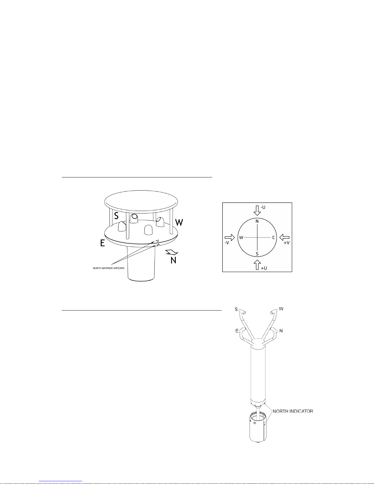
WindMaster Range North Marker and UVW Components
2 Axis Base Station using WindSonics and required Configuration Settings:-
1405-PK-038 WindSonic Option 2 Black
1405-PK-040 WindSonic Option 3 Black
1405-PK-072 WindSonic Option 2 White
1405-PK-073 WindSonic Option 3 White
1405-PK-420 WindSonic 75 Option 2 Black
1405-PK-423 WindSonic 75 Option 3 Black
Configuration Setting M4,U1,O1,L1,P1,B4,H2,NQ,F1,E2,T1,S4,C2,G0,K0,
2 Axis Base Station using WindSonic M and required Configuration Settings:-
1405-PK-200 WindSonic M Heated
1405-PK-201 WindSonic M Heated
1405-PK-300 WindSonic M Unheated
1405-PK-301 WindSonic M Unheated
Configuration Setting M4,U1,O1,L1,P1,B4,H2,NQ,F1,E2,T1,S4,C2,G0,K0,
2 Axis Base Station using WindObservers and required Configuration Settings:-
1390-65-X-XXX WindObserver 65
1390-70-X-XXX WindObserver 70
1390-75-X-XXX WindObserver 75
1390-90-X-XXX WindObserver 90
Configuration for Non-Heated WindObserver is:-
A0,B4,C1,E1,F1,G0000,H1,J1,K1,L1,M4,NQ,O1,P1,T1,U1,V1,X1,Y1,Z1
Configuration for Heated WindObservers is:-
A0,B4,C1,E1,F1,G0000,H2,J1,K1,L1,M4,NQ,O1,P1,T1,U1,V1,X1,Y1,Z1
Note – Applies to Firmware Version 2387 V6.02 onwards.
3 Axis Base Station using WindMasters and required Configuration Settings:-
1590-PK-020 WindMaster
1561-PK-020 WindMaster Pro
1590-PK-050 WindMaster Pipe Mount
1590-PK-130 WindMaster RA
M4,U1,O1,L1,P1,B4,H2,NQ,E1,T1,S1,C2,A4,I1,J1,V1,X1,G0,K0,F1 1,F2 0,F3 1

Gill Instruments Ltd
_____________________________________________________________________________________________________________
________________________________________________________________________________________________
MetPak/MetPak RG and MetPak Pro Base Stations Page | 9 Issue 1
Doc. No. 1723-PS-0023 October 2018
2.1.4. Radiation Shield
2.1.5. Temperature, Relative Humidity and Dewpoint
2.1.6. Barometric Pressure
Barometric pressure output is provided by a solid-state device fitted on to the circuit board in the
MetPak Base Station Unit Hub box. Vent to atmosphere is via a Gore-Tex type filter which also
protects the pressure sensor from the effects of wind and rain.
A MetSpec Base Station Multi-Plate Radiation Shield provides excellent
protection to the Rotronics temperature and relative humidity sensor,
shielding the probe from unwanted errors, especially from secondary upward
reflecting solar radiation and/or wind blown precipitation/airborne
contaminants. The special shield plate geometry, with its double louvre
design, provides excellent response time performance of quick ambient
temperature changes while still working effectively as a baffle to stop larger
contaminants such as salt or dirt from reaching the Rotronics probe. Due to
the increased protection offered to the Rotronics probe by the MetSpec
shield, the maintenance cycle can be extended. The shield benefits from very
robust material choice and extremely high UV protection requiring no
maintenance. A further benefit of the MetSpec shield design is that the
measured temperature is now even closer to reference temperature
measurements made using artificially aspirated motors without the drawbacks
of such systems (power and the maintenance of moving parts).
Hygroclip
The MetPak Base Station MetSpec
shield contains a Rotronic Hygroclip
module. It is a complete instrument, with
integrated temperature compensation.
Calibration data is maintained within the
integrated electronics. It provides digital
output signals for Relative Humidity,
Temperature and Dewpoint.
Gore-Tex
type filter

Gill Instruments Ltd
_____________________________________________________________________________________________________________
________________________________________________________________________________________________
MetPak/MetPak RG and MetPak Pro Base Stations Page | 10 Issue 1
Doc. No. 1723-PS-0023 October 2018
2.1.7. Precipitation (Digital Input 1).
MetPak RG and MetPak Pro Base Stations:–
Rainfall can be measured by the well-proven tipping bucket method. Rain is collected by a funnel
and is passed to one of the two buckets situated at either end of a short balance arm. The balance
arm tips when the first bucket is full, emptying this bucket and positioning the second bucket under
the funnel. The tipping process repeats indefinitely as long as the rain continues to fall, with each
tip corresponding to a fixed quantity of rainfall; at each tip the moving arm forces a magnet past a
reed switch, causing contact to be made for a few milliseconds.
The Digital input (DIG1), detects when two dedicated terminals are short circuited (less than 1k
ohm). Rain levels are provided by reading the number of switch closures taking place over each
output rate time period (default one reading per second). Then multiplying this number by the Rain
Gauge count figure set using MetSet (e.g. 0.2mm per switch closure) and outputting the result in
the data string.
2.1.8 PRT Temperature (PRT Input)
An external 2 or 4 wire PT100 device can be connected to a MetPak Pro Base Station to provide
an additional remote temperature measurement.
2.1.9 Analogue Sensor 1
An external remote analogue sensor, 0-5v/4-20mA output, can be connected to a MetPak
Pro Base Station AN1 input.
2.1.10 Analogue Sensor 2
An external remote analogue sensor, 0-5v/4-20mA output, can be connected to MetPak
Pro Base Station AN2 input.
2.1.11 Status of MetPak Sensors
Outputs the MetPak Base Station Sensors Status Code (see para 8.3.2).
2.1.12 Supply Voltage
The DC Supply voltage measured at the MetPak Base Station unit is output in the Base Station
Digital Data Output string.

Gill Instruments Ltd
_____________________________________________________________________________________________________________
________________________________________________________________________________________________
MetPak/MetPak RG and MetPak Pro Base Stations Page | 11 Issue 1
Doc. No. 1723-PS-0023 October 2018
2.2. MetPak Base Station Range default ASCII Output Summary
MetPak 2 Axis Base Station Default Data String
Node, Relative Wind Direction, Relative Wind Speed, Pressure, Humidity, Temperature, Dewpoint,
Supply Voltage, Status, Checksum.
STX>Q,170,000.08,1019.5,035.0,+024.7,+008.3,+04.9,00,<ETX>55 & (CR,LF)
MetPak 3 Axis Base Station Default Data String
Node, Relative Wind Direction, Relative Wind Speed, W Axis, Pressure, Humidity, Temperature,
Dewpoint, Supply Voltage, Status, Checksum.
STX>Q,170,000.08,+000.02, 1019.5,035.0,+024.7,+008.3,+04.9,00,<ETX>55 & (CR,LF)
MetPak RG 2 Axis Base Station Default Data String
Node, Relative Wind Direction, Relative Wind Speed, Pressure, Humidity, Temperature, Dewpoint,
Digital Input 1, Supply Voltage, Status, Checksum.
<STX>Q,014,000.06,1011.2,042.1,+023.0,+009.4,0000.000,+04.9,00,<ETX>40 & (CR,LF)
MetPak RG 3 Axis Base Station Default Data String
Node, Relative Wind Direction, Relative Wind Speed, W Axis, Pressure, Humidity, Temperature,
Dewpoint, Digital Input 1, Supply Voltage, Status, Checksum.
<STX>Q,014,000.06,+000.02,1011.2,042.1,+023.0,+009.4,0000.000,+04.9,00,<ETX>40 &
(CR,LF)
MetPak Pro 2 Axis Base Station Default Data String
Node, Relative Wind Direction, Relative Wind Speed, Pressure, Humidity, Temperature, Dewpoint,
PRT, Analogue Input 1, Analogue Input 2, Digital Input 1, Supply Voltage, Status, Checksum.
<STX>Q,249,000.01,1017.3,049.2,+021.4,+010.3,+040.45,+000.06,+000.04,0000.000,+11.6,00,<
ETX>7C & (CR,LF)
MetPak Pro 3 Axis Base Station Default Data String
Node, Relative Wind Direction, Relative Wind Speed, W Axis, Pressure, Humidity, Temperature,
Dewpoint, PRT, Analogue Input 1, Analogue Input 2, Digital Input 1, Supply Voltage, Status,
Checksum.
<STX>Q,249,000.01,+000.02,1017.3,049.2,+021.4,+010.3,+040.45,+000.06,+000.04,0000.000,+1
1.6,00,<ETX>7C & (CR,LF)

Gill Instruments Ltd
_____________________________________________________________________________________________________________
________________________________________________________________________________________________
MetPak/MetPak RG and MetPak Pro Base Stations Page | 12 Issue 1
Doc. No. 1723-PS-0023 October 2018
3. TECHNICAL SPECIFICATION
Wind Measurement
Parameters Polar Wind Speed & Direction (2 axis sensor) plus Vertical axis
(3 axis sensor) or U and V Vectors (2 axis sensor) or U, V and W
vectors for 3 axis sensor.
Units of Measurement m/s, knots, mph, kph, ft/min
Wind Speed
-
Refer to Supplied Anemometer Manual for full details
Range 0-45m/s WindMaster
0-60m/s WindSonic/WindSonic M
0-65m/s WindMaster Pro
0-70m/s WindObserver 70
0-75ms WindSonic 75/WindObserver 75
0-90m/s WindObserver 90
Accuracy 2% @12m/s
Resolution 0.01m/s
Threshold 0.01m/s
Wind Direction
Range 0-359 Degrees – No dead band
Accuracy 3@12 m/s WindSonics and WindSonic M
2@12 m/s WindObservers and WindMasters
Resolution 1
Air Temperature
(Hygro
clip)
Type Pt 100 1/3 Class B
Range -35C to +70C
Accuracy 0.1C
Resolution 0.1C
Units of Measure C or F
Relative Humidity
(Hygroclip)
Range 0-100%
Accuracy 0.8% @ 23C
Resolution 1%
Units of Measure % RH
Dew Point
Resolution 0.1C
Accuracy 0.15C (23C ambient temperature @ 20C dew point)
Units of Measure C or F
Barometric Pressure
Range 600 to 1100hPa
Accuracy 0.5hPa
Resolution 0.1hPa
Units of Measure hPa, mbar, mmHg, InHg
Compensated for Temperature dependency –20C to +70C

Gill Instruments Ltd
_____________________________________________________________________________________________________________
________________________________________________________________________________________________
MetPak/MetPak RG and MetPak Pro Base Stations Page | 13 Issue 1
Doc. No. 1723-PS-0023 October 2018
Inputs
-
MetPak Pro
Base Station
(MetPak RG
Base Station
, Digital
Input only).
Analogue 1 (AN1) 0 to 5V or 4 to 20mA powered or Analogue Sensor Powered.
Analogue 2 (AN2) 0 to 5V or 4 to 20mA powered or Analogue Sensor Powered.
Analogue Input A-D
Conversion 12 bit resolution with an accuracy of 0.1% of reading, +35uV
offset (voltage inputs) or 0.5uA (current inputs).
Analogue Input Impedance Input impedance for 0-5v input is 330 k ohm.
Input impedance for 4-20mA input is 47 ohms.
PRT 4 wire PRT, Pt100 conforms to IEC 60751
Digital Input (DIG1)
Rain Gauge
Contact Closure input (tipping bucket rain gauge) capable of
capturing events up to 10Hz
Digital Input Capable of detecting an event with a duration of greater than
1.4mS.
Digital Input Capable of detecting a space between events (i.e. terminals
open-circuit) with a duration of greater than 11mS.
Digital Input Capable of reading a switch contact closure providing the total
Digital Switch contact resistance (contact and cabling) is less
than 1k ohm.
Outputs
Digital Outputs RS232, RS422, *RS485 (*2 wire point to point) or SDI-12.
(RS232 point to point and RS485 2 wire networkable –
MODBUS RTU/ASCII)
Baud Rates 1200 (SDI-12), 4800-57600 (ASCII RS232, RS422, *RS485)
9600-19200 (MODBUS RTU/ASCII)
Protocols ASCII, SDI-12 V1.3, NMEA 0183 (MetPak only) or MODBUS
RTU/ASCII
Data Output 1 reading per second (1 Hz), 1 reading per 2 seconds, 1
reading per 4 seconds or Polled Mode
MetPak Status Status codes provided within the data message string
*
RS485 2 wire point to point only.
Power Supply
Input voltage (RS232, RS422,
RS485) 12v to 30v dc
Current at 12v Default setting (first value is Base Station current)
15mA MetPak Base Station Current
23mA MetPak RG Base Station Current
23mA MetPak Pro Base Station Current
+ 9mA at 12v with WindSonic
+13mA at 12v dc with WindSonic 75
+ 9mA at 12v WindSonic M (plus heater power)
+ 50mA at 12v WindObserver 70/75/90 (plus Heater power)
+ 55mA at 12v WindMaster/WindMaster Pro

Gill Instruments Ltd
_____________________________________________________________________________________________________________
________________________________________________________________________________________________
MetPak/MetPak RG and MetPak Pro Base Stations Page | 14 Issue 1
Doc. No. 1723-PS-0023 October 2018
Input Voltage SDI-12 9.6v to 16v dc (12v nominal)
Current 30mA MetPak Base Station Current
35mA MetPak RG Base Station Current
35mA MetPak Pro Base Station Current
+ 9mA at 12v with WindSonic
+13mA at 12v dc with WindSonic 75
+ 9mA at 12v WindSonic M (plus heater power)
+ 50mA at 12v WindObserver 70/75/90 (plus Heater power)
SDI-12 not applicable with WindMaster/Pro
Environmental
MetPak
Base Station
Range
Protection Class IP65
EMC BS EN 61326
Operating Temperature -35C to +70C
Storage Temperature -40C to +80C
Humidity 0-100%
RoHS Compliant Yes
Mechanical
MetPak
Base Station
Range
External Construction UV Stabilised white thermoplastic (MetSpec shield and
Hygroclip Mountings) and anodized Aluminium bracket
Fittings Stainless Steel 316 bracket fittings supplied for clamping to a
vertical pipe diameter of diameter 30mm to 58mm.
Overall Dimensions
MetPak Base Station
MetPak RG Base Station
MetPak Pro Base Station
201mmx287mmx129mm (excluding bracket clamp)
Weight
MetPak Base Station
MetPak RG Base Station
MetPak Pro Base Station
1.7kg (including bracket and 10M cable)
Software
MetSet Configuration
MetView
Free PC Software providing the means of configuration of the
Base Station Unit.
Free PC Software providing the means of viewing Base Station
data and providing a basic logging facility.

Gill Instruments Ltd
_____________________________________________________________________________________________________________
________________________________________________________________________________________________
MetPak/MetPak RG and MetPak Pro Base Stations Page | 15 Issue 1
Doc. No. 1723-PS-0023 October 2018
4. PRE-INSTALLATION
4.1. Equipment supplied
1723-xA-x-xxx 2 Axis MetPak Base Station Variant unit with a 10 metre cable from the
Hub box to connect to a Gill Anemometer.
Or
1723-xC-x-xxx 3 Axis MetPak Base Station Variant unit with a 10 Metre cable from the
Hub box to connect to a Gill Anemometer.
and A Gill anemometer either as part of the Base Station part structure or ordered separately.
and 8 way connector inside the hub box for power and communication.
and Mounting bracket plate/nuts and bolts in a box.
and Base Station Range User Manual, MetSet and MetView Software on a CD in the Base
Station box (this manual).
and Product Test Report.
4.1.1. Optional Extras:
Item
Part Number
Barometric Pressure Hub Box Gore-Tex filter spares kit 1723-PK-024
Hygroclip Temperature and Humidity Filter Replacement Kit (two filters) 1723-PK-025
Hygroclip HC2-S3-GI 037-04263
Heater Interface Box 1723-PK-099
Rain Gauge. ARG100 Tipping bucket (no cable attached) 1723-PK-076
Junction Box with internal terminating pcb (for MetPak Pro). 1723-PK-201
Terminating pcb (used in Junction box) for MetPak Pro. 1723-PK-202
Pack of 4 brackets for Pole Mounting the Junction Box for MetPak Pro 1723-PK-203
Pack of 4 feet for Panel Mounting the Junction Box for MetPak Pro. 1723-PK-204
MetPak Range 1.8 Metre RS232 to USB converter including 5v dc power and
communication configuration cable (8 way MetPak hub box connector fitted one
end and USB connector at the other end).
1723-10-051

Gill Instruments Ltd
_____________________________________________________________________________________________________________
________________________________________________________________________________________________
MetPak/MetPak RG and MetPak Pro Base Stations Page | 16 Issue 1
Doc. No. 1723-PS-0023 October 2018
4.2. Base Station Anemometer 10 Metre Cable Assembly.
Base Station variants come with an integral 10 Metre, Belden 8104 cable (7 wires and a screen)
fitted to the hub box connector J4, (RS422 interface).
The cable is terminated in connector solder contacts for installing into a WindSonic Option 2/3/M
with Clipper Connector or WindMaster/WindMaster Pro Clipper Connector (connectors supplied
with the Wind Sensor).
This Anemometer RS422 cable can be extended using twisted pair screened cable if required
within the bounds of RS422 communication limits and ensuring the anemometer receives its
minimum supply voltage.
The cable provides communication and DC power to the Wind Sensor. Care must be taken
not to short out contacts should the base station be powered before a connector is fitted.
If used with a WindObserver or WindSonic M with Analogue Outputs the 10 metre cable contact
pins will need to be cut off and wire stripped/soldered for use with their respective connectors or
termination into the optional Heater Power Interface Box.
If shortening the 10 Metre cable to a required length, strip and prepare as follows:-
1. Trim back the screened cable outer PVC sheath to 52mm.
2. Trim back the braid and drain wire to 20mm from the outer sheath.
3. Separate braid and drain wire from the foil and cores. Twist braid and drain wires
together.
4. Trim the twisted braid and drain wire to 15mm from the outer sheath and tin ends
5mm.
5. Cut the foil and White/Green wire back to within 5mm of the outer sheath.
6. Strip and tin one end of the White/Green wire removed to 5mm.
7. Locate White/Green wire to twisted braid and drain wire and solder.
8. Insulate the White/Green wire joint.
9. Strip back the connection wires by 4mm and tin solder.
10. Solder the contact pins supplied with the connector to the wires.
11. Note that the hub box sensor connector supplies the correct strain relief for
cables with an outside diameter of 6-12mm.
4.2.1. WindSonic and WindMaster Clipper Connector Assembly Details
Route the cable through the connector parts as in direction shown below (WindSonic connector
shown, the WindMaster Connector is similar).
Cable Sleeve
Contact Pin

Gill Instruments Ltd
_____________________________________________________________________________________________________________
________________________________________________________________________________________________
MetPak/MetPak RG and MetPak Pro Base Stations Page | 17 Issue 1
Doc. No. 1723-PS-0023 October 2018
Whilst squeezing the red retainer in the direction of ARROWS A, pull in the direction of ARROW B.
A A B
Your connector should now resemble the connector in the picture below.
Insert each contact pin until you feel a slight click. If you have inserted the contact into the
incorrect hole it can be removed at this point by simply pulling it out. Please note there will be
some resistance.
WindSonic (Option 2/3/M) and WindMaster/Pro RS422 10 Metre Cable Connections are as
follows:-
Ba
se Station 10 Metre Cable
WindSonic Option 2
and 3 Connector Pin
Wind Sonic M
Non Heated
WindMaster
/WindMaster Pro
Green White
(Sig Gnd)
1
No Connection
4
Orange White
(Supply +)
2
2
11
White Orange
(Supply
-
)
3
3
12
Brown White
RS422+ input)
4
4
2
W
hite Brown
(RS422
–
input)
5
5
1
Blue White
(RS422+ output)
6
6
5
White Blue
(RS422
-
output)
7
7
6
White Green (
Screen
shield)
Cut offwire at sleeve
1
31
Rear View of WindSonic Connector
Rear View of WindMaster Connector

Gill Instruments Ltd
_____________________________________________________________________________________________________________
________________________________________________________________________________________________
MetPak/MetPak RG and MetPak Pro Base Stations Page | 18 Issue 1
Doc. No. 1723-PS-0023 October 2018
Continue to insert all of the contacts you require. Once all of the contacts are inserted squeeze the
2 red retainers (See Arrows A on previous page) into place. NB. The retainer can only be pushed
back into place if the contacts are fully engaged.
Fit the connector to the WindSonic/WindMaster Sensor so that you can finish assembling the
connector.
Screw the back shell onto the connector until it is fully in place. Please note that the final rotations
can be slightly stiff.
Now screw the next part of the connector into place.
Now screw the cable-clamping nut into place.
The connector can now be removed from the WindSonic/WindMaster.
Replace the 31 way WindMaster connector sealing nut with Sealing Nut part 1723-10-109 supplied
with the Base Station unit. This part allows for correct sealing around the outer surface of the wired
10 Metre cable.
NOTE: To disassemble the connector, reverse this procedure.

Gill Instruments Ltd
_____________________________________________________________________________________________________________
________________________________________________________________________________________________
MetPak/MetPak RG and MetPak Pro Base Stations Page | 19 Issue 1
Doc. No. 1723-PS-0023 October 2018
4.2.2. WindObserver (Non Heated units) Connector Assembly Details
Wiring between the Base Station wind sensor 10 Metre cable and a Non Heated WindObserver
19-way Cannon connector variant unit is as follows:-
4.2.3. WindSonic M Heated units Connector Assembly Details
WindSonic M (Heated) RS422 10 Metre Cable Connections to the Heater Power Interface Box
(1723-PK-099).
Note: See also the lid of the Heater Power Interface Box for Connection Details.
Cut off the contact pins connected to the Base Station 10 Metre cable, strip and solder wires.
Connect wires to the Heater Power Interface box as follows:-
Remote Base Station WindObserver 65/70/75/90 (Non Heated)
10 Metre Cable 19 Way Connector
White/Green Cable Screen/Drain wires
Green/White M
Orange/White R
White/Orange D
Brown/White P
White/Brown C
Blue/White U
White/Blue V
No Connection A, E and H
No Connection B, F and G
Remote Base Station Optional Heater Power Interface Box WindSonic M (Heated)
10 Metre Cable 8 Way Terminal Block 9 Way Connector
White/Green 8 1
Green/White 7 No Connection
Orange/White 6 2
White/Orange 5 3
Brown/White 4 4
White/Brown 3 5
Blue/White 2 6

Gill Instruments Ltd
_____________________________________________________________________________________________________________
________________________________________________________________________________________________
MetPak/MetPak RG and MetPak Pro Base Stations Page | 20 Issue 1
Doc. No. 1723-PS-0023 October 2018
4.2.4. WindObserver Heated units Connector Assembly Details
These connection details show the use of the optional Gill Heater Interface box
WindObserver 65/70/75/90 RS422 10 Metre Cable Connections to the Heater Power Interface Box
(1723-PK-099).
Note: See also the lid of the Heater Power Interface Box for Connection Details.
Cut off the contact pins connected to the MetPak Pro Base Station 10 Metre cable, strip and solder
wires. Connect wires to the Heater Power Interface box as follows:-
4.3. Communication Cabling
The Base Station is supplied with a mating 8 way connector for power and communication
connections.
MetPak, MetPak RG and MetPak Pro Base Stations have five communication connection options:
USB (using the 1.8m MetPak RS232 to USB cable, Part No. 1957-10-065).
RS232.
RS422.
RS485 (two wire point to point) or networkable if using Modbus.
SDI-12.
MetPak RG and MetPak Pro Base Stations have a contact closure input connection:
DIG1 (Digital Switch).
MetPak Pro Base Station has in addition various Sensor Input connection options:
AN1 and AN2, Analogue inputs (0-5v or 4-20mA).
PRT. Platinum Resistance Thermometer Input.
It is important that the cable is appropriate for the chosen communication network. The following
sections describe the recommended types and maximum lengths of cable in each case.
This manual suits for next models
2
Table of contents
Other Gill Weather Station manuals
Popular Weather Station manuals by other brands

Creative Play
Creative Play PB114 installation instructions

BALDR
BALDR B0359WST2H2R user manual

Eurochron
Eurochron EFWS 302 operating instructions

HomeMatic
HomeMatic WDC7000 operating manual

La Crosse Technology
La Crosse Technology WS-9043U instruction manual

elsner elektronik
elsner elektronik Suntracer KNX-GPS light Technical specifications and installation instructions