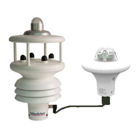
Gill MetConnect THP User manual


1. Welcome.............................................................................................................................5
1.1. Overview of Content...................................................................................................................... 5
1.2. Description of Icons....................................................................................................................... 5
1.3. General Notes................................................................................................................................ 6
1.4. User Manual Revision History ....................................................................................................... 6
2. Product Overview................................................................................................................7
2.1. MetConnect Product Range .......................................................................................................... 7
2.2. MetConnect Specification ............................................................................................................. 8
2.3. MetConnect Component Parts...................................................................................................... 8
2.4. MetConnect Standard Equipment................................................................................................. 8
2.5. Downloadable Software ................................................................................................................ 8
2.6. MetConnect Accessories ............................................................................................................... 9
2.7. MetConnect CE, UKCA, FCC conformity ........................................................................................ 9
2.8. Right to change and revise ............................................................................................................ 9
3. Set-up MetConnect ...........................................................................................................10
3.1. Introduction................................................................................................................................. 10
3.2. Configurable features.................................................................................................................. 10
3.3. MetSet Set-Up Software.............................................................................................................. 11
3.4. Connect MetConnect to MetSet ................................................................................................. 12
3.5. Set-Up Communication Protocol................................................................................................. 12
3.6. Set-up MetConnect integrated sensors....................................................................................... 12
3.7. Set-up additional sensor inputs................................................................................................... 12
4. Install MetConnect............................................................................................................13
4.1. Introduction................................................................................................................................. 13
4.2. Select an appropriate site............................................................................................................ 13
4.2.1. Physical Location ......................................................................................................................... 13
4.2.2. Distance from the power supply and data collection system ..................................................... 13
4.2.3. EMC Interference......................................................................................................................... 14
4.3. Prepare the equipment ............................................................................................................... 14
4.3.1. Power and Communications Cable.............................................................................................. 14
4.3.2. Connector Pin Allocation............................................................................................................. 15
4.3.3. Power and Earthing ..................................................................................................................... 15
Power....................................................................................................................................................... 15
Earthing ................................................................................................................................................... 16
4.3.4. Connection of additional sensors................................................................................................ 16
4.4. Install the MetConnect................................................................................................................ 17
4.4.1. Select Alignment.......................................................................................................................... 17
4.4.2. Install MetConnect on a Pipe or Pole .......................................................................................... 17
4.4.3. Install MetConnect to a Panel or Wall......................................................................................... 18
4.4.4. Install Cable Strain Relief............................................................................................................. 18
4.4.5. Install Earthing............................................................................................................................. 18

5. Use MetConnect................................................................................................................ 19
5.1. Introduction................................................................................................................................. 19
5.2. MetConnect data......................................................................................................................... 19
5.3. Status Codes ................................................................................................................................ 19
5.4. MetView software....................................................................................................................... 19
5.5. Fault Finding ................................................................................................................................ 19
6. Maintain MetConnect .......................................................................................................20
6.1. Introduction................................................................................................................................. 20
6.2. Product Maintenance.................................................................................................................. 20
6.2.1. General Maintenance.................................................................................................................. 20
6.2.2. Wind Sensor................................................................................................................................. 20
6.2.3. Pressure Sensor ........................................................................................................................... 21
6.2.4. Shield ........................................................................................................................................... 21
6.2.5. Temperature and Humidity Sensor ............................................................................................. 21
6.2.6. MetConnect Mounting Bracket Plates, Bolts, Connectors and Cable Clamps ............................ 21
6.2.7. Cable clamps................................................................................................................................ 21
6.2.8. Earthing........................................................................................................................................ 21
6.2.9. Additional Sensors....................................................................................................................... 21
6.3. Calibration ................................................................................................................................... 21
6.3.1. Pressure Sensor ........................................................................................................................... 21
6.3.2. Other Gill Instruments Sensors.................................................................................................... 21
6.3.3. Additional Sensors....................................................................................................................... 21
6.4. Fault Finding ................................................................................................................................ 22
6.5. Safe Mode.................................................................................................................................... 23
6.6. Product Repair............................................................................................................................. 23
6.6.1. Minor Repairs .............................................................................................................................. 23
6.6.2. Major Repairs .............................................................................................................................. 23
6.7. Warranty Repairs......................................................................................................................... 23

Appendix A - Technical Specification.......................................................................................24
Appendix B - MetConnect Connector Pin Allocation ................................................................27
.......................................28
.............................................................................32
....................................................................................33
................................................................................................34
.......................................................................39
.................................................................41
...............................................................44
......................................................................46
..................................................................................51
............................................................................................52
...............................................................................55
....................................................57

1. Welcome
Welcome to the MetConnect user manual.

Document Version
Release Date
Key Changes
0.82
25 Nov 2021
“Final” draft for Review
1
15 Dec 2021
First Release

2. Product Overview
S = Sensor supplied as part of MetConnect model
C = Connector available for user supplied sensor
MetConnect
THP
MetConnect
One
Temperature
S
S
Humidity
S
S
Pressure
S
S
Wind speed and direction
C
S (integrated)
Analogue Sensor Input 1
C
C
Analogue Sensor Input 2
C
C
PRT
C
C
Rain
C
C


Accessory
Gill Instruments Part Number
Connector, M12, 8 way, field wireable
1733-PK-002
Cable, for power and communications, 2m
with M12, 8 way over moulded connector
1733-PK-012
Cable, for power and communications, 10m
with M12, 8 way over moulded connector
1733-PK-013
Cable, for power and communications, 20m
with M12, 8 way over moulded connector
1733-PK-014
Bracket Mounting Plate, replacement
1733-PK-022
Cable, M12 to USB, for MetConnect set-up
1733-PK-031
Sensor, replacement pressure sensor
1733-PK-040
Sensor, replacement temperature and humidity sensor
1733-PK-041
Heater Interface box for external anemometer
1733-PK-099

3. Set-up MetConnect
o
o


4. Install MetConnect
o
o
o
o

o
o
Cable Feature
Recommendation
Wire Size
24 AWG
Strand Size
7 x 32 AWG
Pairing
Twisted pair with drain wire
Screening
Screened with aluminium tape
Outer Diameter
6-8mm
Number of pairs required and
maximum cable length
RS232
3 pairs, max. length = 6.5m
RS422
4 pairs, max. length = 1000m
RS485
4 pairs, max. length = 1000m
SDI-12
2 pairs, max. length = 90m

Power
Pin
Wire
Colour
RS-232
RS-422
RS-485
SDI-12
1
White
Power Ground
Power Ground
Power Ground
Power Ground
2
Brown
Rx-
Rx-
Rx-
-
3
Green
-
Tx+
Tx+
-
4
Yellow
Tx-
Tx-
Tx-
-
5
Grey
-
Rx+
Rx+
-
6
Pink
Power (V+)
Power (V+)
Power (V+)
Power (V+)
7
Blue
Signal Ground
Signal Ground
Signal Ground
Signal Ground
8
Red
-
-
-
SDI-12 Signal

Earthing
Earth
Point

NORTH
MARKER
ARROWS
MOUNTING
BRACKET
PLATES


5. Use MetConnect

6. Maintain MetConnect
This manual suits for next models
1
Table of contents
Other Gill Weather Station manuals