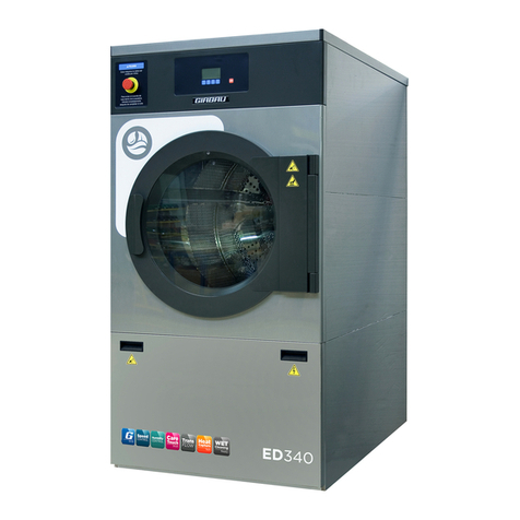
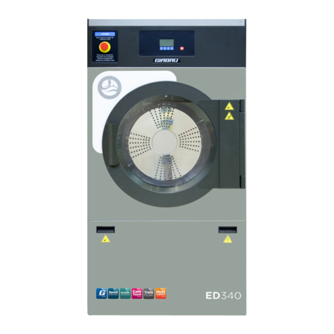
GIRBAU ED460 Service manual

Code No. 549758
Rev. nº 10/0418
Model
From Machine No.
ED260
ED340
ED460
ED660
ED900
ED1250
2,215,001
2,240,001
2,265,001
2,290,001
2,480,001
2,470,001
Installation Instruction Manual for
ED dryers
GIRBAU, SA
Crta de Manlleu, km. 1
08500 VIC (Barcelona) • SPAIN
National sales:
T.(+ 34) 902 300 359
International sales:
T.(+ 34) 938 862 219
Service:
T.(+ 34) 902 300 357
www.girbau.es
For USA and CANADA:
CONTINENTAL GIRBAU Inc.
2500 State Road 44
WI 54904 Oshkosh • USA
Tel. 1(920) 231-8222
www.continentalgirbau.com
EN
Installation
ED260/ED340
ED460/ED660
ED900/ED1250

Safety instructions 2
Code No. 549758
Rev. nº 10/0418
CONTENTS
SAFETY INSTRUCTIONS ................................................................................................................................. 4
1. GENERAL DESCRIPTION OF THE MACHINE ............................................................................................ 7
1.1. Dryer description .......................................................................................................................................... 7
1.1.1. Construction features ........................................................................................................................ 7
1.1.2. Functional features ............................................................................................................................ 7
1.2. Machines with gas heating. Diagram and description of the burner ........................................................... 8
1.2.1. Models ED260, ED340, ED460 and ED660 ...................................................................................... 8
1.2.2. Models ED900 and ED1250 .............................................................................................................. 9
1.3. Machines with electric heating. Description of the electric circuit ............................................................. 10
1.4. Machines with steam heating. Description of the steam heat exchanger ................................................. 10
1.5. Dos and don'ts in using the machine ......................................................................................................... 10
1.6. Protection, safety and control elements .................................................................................................... 11
1.7. EC declaration of conformity ..................................................................................................................... 12
2. Receipt, storage and transport ................................................................................................................. 14
2.1. Receipt ....................................................................................................................................................... 14
2.2. Storage ...................................................................................................................................................... 15
2.3. Transport ................................................................................................................................................... 16
2.3.1. Transporting with packaging. Fork-lift truck .................................................................................... 16
2.3.2. Transporting with packing crate using a hoist ................................................................................. 17
2.3.3. Separating the machine from the base of the packing crate ........................................................... 17
2.4. Table of weight and dimensions ................................................................................................................ 19
3. Location ....................................................................................................................................................... 20
3.1. General information and location ............................................................................................................... 21
3.2. Areas of usage ........................................................................................................................................... 22
3.3. Positioning and levelling the machine ....................................................................................................... 23
3.4. Anchoring the dryer ................................................................................................................................... 23
3.5. Environment conditions ............................................................................................................................. 24
3.6. Ventilation conditions and extraction in the premises ............................................................................... 25
3.6.1. Minimum ventilation openings. Machines with electric heating ....................................................... 25
3.6.2. Ventilation openings. Machines with gas heating ........................................................................... 26
3.7. Height of the work stations ........................................................................................................................ 27
3.7.1. Models ED260, ED340, ED460 and ED660 .................................................................................... 27
3.7.2. Models ED900 and ED1250 ............................................................................................................ 29
4. Technical and connection details for the machine ................................................................................. 30
4.1. General technical details ........................................................................................................................... 30
4.2. Electrical connection details. Electrical protection devices ....................................................................... 31
4.2.1. Models with gas or steam heating ................................................................................................... 32
4.2.2. Machines with electric heating ........................................................................................................ 34
4.3. EC certified models. Specific values for models with GAS heating .......................................................... 36
4.3.1. Heating data .................................................................................................................................... 36
4.3.2. Maximum NOx values and classification ......................................................................................... 37
4.3.3. Categories of commercially available gases ................................................................................... 37
4.3.4. Details of gas connection ................................................................................................................ 38
4.3.5. Electric power and consumption. Machines with gas heating ......................................................... 38
4.4. AGA certified models. Specific values for models with gas heating .......................................................... 39
4.4.1. Heating data .................................................................................................................................... 39
4.4.2. Details of gas connection ................................................................................................................ 39
4.4.3. Electric power and consumption. Machines with gas heating ......................................................... 39
4.5. ETL certified models. Specific values for models with gas heating ........................................................... 40
4.5.1. Heating data .................................................................................................................................... 40
4.5.2. Details of gas connection ................................................................................................................ 40
4.5.3. Electric power and consumption. Machines with gas heating ......................................................... 40
4.6. Specific values for models with steam heating .......................................................................................... 41
4.6.1. Steam heating details ...................................................................................................................... 41
4.6.2. Electric power and consumption. Machines with steam heating ..................................................... 41
4.7. Specific values for models with electric heating ........................................................................................ 42
4.7.1. NOMINAL HEATING power ............................................................................................................ 42

Safety instructions 3
Code No. 549758
Rev. nº 10/0418
4.7.2. REDUCED HEATING power ........................................................................................................... 43
4.8. Exhaust ducting. Technical and connection details ................................................................................... 44
4.9. Wiring diagram ........................................................................................................................................... 45
4.9.1. Measurements for the installation plan and location ....................................................................... 46
5. CONNECTING THE MACHINE ................................................................................................................... 47
5.1. Electrical requirements .............................................................................................................................. 47
5.1.1. Characteristics of the electrical wiring ............................................................................................. 48
5.1.2. Models with breaker switch ............................................................................................................. 49
5.1.3. Models without breaker switch ........................................................................................................ 51
5.2. Steam connection ...................................................................................................................................... 51
5.2.1. Characteristics of the installation ..................................................................................................... 51
5.3. Gas connection .......................................................................................................................................... 52
5.3.1. Characteristics of the gas installation ............................................................................................. 54
5.3.2. Gas supply connection .................................................................................................................... 54
5.4. Changing the type of gas ........................................................................................................................... 55
5.4.1. Gas type change label ..................................................................................................................... 56
5.4.2. Changing the combustion adjustment elements. Models ED260, ED340, ED460 and ED660 ...... 57
5.4.3. Changing the combustion adjustment elements. Models ED900 and ED1250 .............................. 58
5.5. Connecting the exhaust ducting ................................................................................................................ 60
5.5.1. Specifications for the ducting .......................................................................................................... 61
5.5.2. Exhaust extraction for several machines ........................................................................................ 62
6. EMERGENCY STOP IN COIN-OP INSTALLATIONS ................................................................................. 63
7. STARTING A DRYING CYCLE FROM AN EXTERNAL DEVICE .............................................................. 63
7.1. Connecting to a central vending unit and configuring the machine ........................................................... 63
8. OPTIONS ...................................................................................................................................................... 63
8.1. AFS option (Fire prevention) ..................................................................................................................... 63
9. INITIAL START-UP OF THE MACHINE ...................................................................................................... 64
9.1. Initial checks .............................................................................................................................................. 64
9.2. Machines with gas heating. Analysis of the combustion gases ................................................................ 65
9.2.1. Adjusting the position of the Venturi. Models ED260, ED340, ED460, ED660 ............................... 66
9.3. Machines with electric heating ................................................................................................................... 66
10. Removal from service and dismantling ................................................................................................. 67

Safety instructions 4
Code No. 549758
Rev. nº 10/0418
IMPORTANT SAFETY INSTRUCTIONS
WARNING – Risk of Fire:
WARNING – To reduce the risk of fire, electric shock, or injury to persons when using your appliance, follow
basic precautions, including the following:
Clothes dryer installation must be performed by a qualified installer.
Install the clothes dryer according to the manufacturer’s instructions and local codes.
Do not install a clothes dryer with flexible plastic venting materials. If flexible metal (foil type) duct is
installed, use duct that has been investigated and found acceptable for use with clothes dryers.
Flexible venting materials are known to collapse, be easily crushed, and trap lint. These conditions
will obstruct clothes dryer airflow and increase the risk of fire.
To reduce the risk of severe injury or death follow all installation instructions.
SAVE THIS INSTRUCTIONS.
WARNING
TRANSPORT, INSTALLATION, INSPECTION, MAINTENANCE, REPAIR OR MODIFICATION
ROUTINES ON GIRBAU EQUIPMENT
1. The actions described in these instructions are strictly reserved for contractually AUTHORISED
TECHNICAL SERVICES (ATS) and personnel who have successfully completed training by Girbau
SA.
2. The company responsible for the Authorised Technical Service accepts full liability for the work done
and any possible consequences that may derive from it.
3. Any actions carried out by personnel who are not authorised by the manufacturer will be considered
to be improper and will result in the automatic voiding of the machine’s warranty.
4. The manufacturer will not accept responsibility for any physical and/or material damage caused by
actions performed on the machine undertaken by unauthorised personnel.
5. Do not store or install the machine in areas exposed to the ELEMENTS or where it may be splashed
by water.
6. The room where the machine is located MUST comply with the environmental conditions (air venting,
temperature, humidity, etc.) specified in the technical specifications table. NEVER INSTALL THE
MACHINE IN ENVIRONMENTS where it will be splashed with water or where there is a very high
level of humidity in the atmosphere.
7. All installations required for the proper operation of the machine MUST be carried out by a duly
accredited Registered Installation Contractors, in compliance with the legal regulations applicable in
the country of use.
8. Once the corresponding operation has been performed, the ATS staff must perform the final
machine inspection.
9. Avoid carrying out any action on the machine without having first read and understood the machine’s
Installation and Operating Manuals, paying special attention to the Safety Instructions.
10. In any action that modifies the values of the machine’s specifications plate, it should be borne in
mind that:
- It is the responsibility of the ATS to check that the external installation for the machine has been
modified and adapted to the new requirements, particularly to those regarding ducting and
electrical protection.
- It is the responsibility of the ATS to update the specifications plate, in accordance with the new
operation conditions, once the final machine inspection has been performed.

Safety instructions 5
Code No. 549758
Rev. nº 10/0418
11. Carrying out transport, installation, inspection routines, adjustments, maintenance, repairs, cleaning
or any work on the machines without applying safety measures or having the necessary technical
know-how can lead to ELECTRICAL SHOCK OR SERIOUS ACCIDENTS.
12. When tools designed for specific transport, installation, maintenance and repair routines are
available, their use is compulsory in order to avoid unnecessary risks.
13. Before carrying out any procedures on machines fitted with pneumatic or hydraulic circuits:
- Make the machines COMPLETELY SAFE by following the instructions set out in the
corresponding Manuals or by wedging them with wooden blocks where necessary.
- Bear in mind that working on a component without having previously understood the role that it
performs in the circuit as a whole involves a high risk of suffering a SERIOUS ACCIDENT.
14. BEFORE CARRYING OUT ANY inspection routine, adjustment, maintenance, repairs, cleaning or
any work on the machine, DISCONNECT IT FROM ALL THE ENERGY SOURCES.
- COMPLETELY disconnect the machine from the power supply and prevent the possibility of
accidental reconnection by mechanically locking the automatic external switch and/or the switch
breaker. Stopping the machine with the NORMAL STOP key or push-button is not enough.
- Disconnect the electrical connection of any circuit external to the machine; for example external
dosing equipment, external vending units, folders or ironer feeders. These circuits are
independent of the supply to the machine.
- Before beginning any procedure on machines equipped with an inverter or equipment with
capacitative loads, wait for at least five minutes (10 minutes on equipment with a power rating
greater than 25 kW) after the electrical disconnection, to eliminate risk of residual voltage.
- Close and mechanically lock the manual WATER, GAS, STEAM, THERMAL OIL,
COMPRESSED AIR, etc. supply valves.
- Check that no part of the machine is at an excessively high temperature and that no parts are in
movement through inertia.
15. DANGER! Some fault localisation procedures require checking at different points of the electric
circuit with the machine connected to the power supply and other supply sources. When carrying out
these procedures, respect the following instructions:
- The appropriate checks must be carried out by ONLY ONE PERSON.
- During these procedures, ONLY remove the protective covers from the electric circuit and/or the
inverter. Never remove the covers protecting the moving parts of the machine.
16. THE MANUFACTURER ACCEPTS NO RESPONSIBILITY IF THESE SAFETY INSTRUCTIONS
AND ALL THE INFORMATION IN THE CORRESPONDING MANUALS ARE NOT FOLLOWED.
KEEP THESE INSTRUCTIONS IN A SAFE PLACE.

Safety instructions 6
Code No. 549758
Rev. nº 10/0418
SYMBOLS USED IN MACHINE LABELLING
Electrical risk
Protective guard for elements carrying
an electric current.
High temperature risk
Handle with caution.
Use adequate protection.
Mechanical risk
Protective guard for moving parts.
Risk of inhaling harmful or irritant
vapours
Keep the doors/covers closed.
Use adequate protection.
Flame risk (only on some machines)
Protective guard for flame.
Risk of falling
Use proper access and safety methods.
Access prohibited
Refer to instruction
manual/booklet
SYMBOLS USED IN THIS MANUAL
Symbol used to highlight a possible
HAZARD, WARNING or NOTE.
This symbol is used to emphasise a
particular explanation.
TRANSLATION OF THE ORIGINAL MANUAL

General description 7
Code No. 549758
Rev. nº 10/0418
1. GENERAL DESCRIPTION OF THE MACHINE
This INSTALLATION, OPERATION AND MAINTENANCE manual applies to dryer models ED240, ED340,
ED460, ED660, ED900 and ED1250 in the different heating and control systems.
1.1. Dryer description
The essential features of the dryer are as follows:
1.1.1. Construction features
Front-loading rotary dryer.
Stainless steel drum.
Drum with large perforation area consisting of pressed holes that aid the distribution of the drying air flow.
Drum with rear axle supported by double bearings.
Double glazed drum access door with air cavity (an option without air cavity is also available).
Lint filter that has a large surface area and is easy to access for cleaning.
Rust resistant external structure.
The drum rotation by an asynchronous AC motor controlled by an inverter.
Suction by an asynchronous AC motor controlled by inverter for ED900 and ED1250 models only.
Drying flow output adjustable with variable opening flap.
Three possible heating options:
o Electric heaters
o Atmospheric burner with gas input controlled by double winding solenoid, Class B and Class J (in
accordance with EN1020).
o Pressurised steam exchanger.
1.1.2. Functional features
Dryer operation controlled by microprocessor.
Control of the temperature, drying time, drum rotation speed and linen wetness.
Suction motor speed control on ED900 and ED1250 models only. This motor is operated by an inverter,
which makes it possible to adjust the ventilation to the particular characteristics of each facility and optimise
its performance.
Operation of the machine adaptable to the possibilities of the installation and the needs of the user.
Motor rotation safety control.
Transmission by belt between the motor and the drum shaft.
Detection of air flow losses by pressure switch on models ED260, ED340, ED460 and ED660; and by
mechanical pressure switch on models ED900 and ED1250.
Inverter activated motor controlled by the microprocessor. This technology takes advantage of all the
features offered by inverter technology, resulting in a significant reduction in noise, vibration and wear on all
the machine components and the matching of the drum rotation speed to the specific needs of each
program.
Multiple controls that ensure the safe use of the machine.

General description 8
Code No. 549758
Rev. nº 10/0418
1.2. Machines with gas heating. Diagram and description of the burner
1.2.1. Models ED260, ED340, ED460 and ED660
Diagram of the burner (Fig. 1.1)
A .......... Connection point
B .......... Control
C .......... Solenoid valve
D .......... Injector
E .......... Venturi pipe
F .......... Ducting
G ......... Ignition electrode
H .......... Ionisation electrode
J .......... Burner
Fig. 1.1
Description of operation (Fig. 1.1)
When the dryer control requests heating, the
burner control system (B) activates the ignition
electrode (G) to generate a spark;
simultaneously power is fed to the solenoid
valve (C) to open the gas flow.
The gas enters the burner via a single nozzle
(D).
The ionisation electrode (H) detects the flame.
If the presence of a flame has not been
detected after a certain time following the
ignition order, the solenoid valve closes, an
alarm report is issued and the burner control
enters safety mode.
Fig. 1.2
For further information refer to paragraph 1.6. Protection, safety and control elements.

General description 9
Code No. 549758
Rev. nº 10/0418
1.2.2. Models ED900 and ED1250
Fig. 1.3
Fig. 1.4
Diagram of the burner
A ....... Connection point
B ....... Control
C ....... Solenoid valve
D ....... Injector
E ....... Deflector
F ....... Ducting
G ...... Ignition electrode
H ...... Ionisation electrode
J ....... Burner
Description of operation (Fig. 1.3 and 1.4)
When the dryer control requests heating, the burner control system (B) activates the ignition electrode (G) to
generate a spark; simultaneously power is fed to the solenoid valve (C) to open the gas flow. The gas enters
the burner via a single nozzle (D). Then, the ionisation electrode (H) detects the flame. If the presence of a
flame has not been detected after a certain time following the ignition order, the solenoid valve closes, an
alarm report is issued and the burner control enters safety mode.
Fig. 1.5
For further information refer to paragraph 1.6. Protection, safety and control elements.
ED900 and ED1250 models are equipped with 2 electronic ignition controls (Fig. 1.3/B and 1.4/B). One of the
controls operates two electrodes and another triggers the third electrode on model ED900 or the other two
electrodes on model ED1250. A modular system makes it possible to turn on only two burners or all the
burners, as required.

General description 10
Code No. 549758
Rev. nº 10/0418
1.3. Machines with electric heating. Description of the electric circuit
Electric heaters
Electric heating elements mounted in an array, which heat the air entering the dryer.
Description of the operation
When the dryer control calls for heating, the contactors supplying the electric heaters are activated.
Further information, see the wiring diagram provided with the machine.
1.4. Machines with steam heating. Description of the steam heat exchanger
Steam heat exchanger
An array of aluminium finned copper pipes for pressurised steam that heat the air entering the dryer.
Description of the operation
When the dryer control requests heating, this activates the solenoid valve that allows the passage of steam
through the heat exchanger and heats the air entering the drum.
Additionally, models ED900 and ED1250 have a flap that enables a bypass for the cooling phase. In the cooling
phase, a linear actuator is activated which tilts the flap that shuts of the passage of air through the coil and
enables the passage of air through a duct without heating.
1.5. Dos and don'ts in using the machine
CAUTION!
APPROPRIATE USE:
THIS MACHINE HAS BEEN CONCEIVED AND DESIGNED FOR THE INDUSTRIAL DRYING OF LAUNDRY
ITEMS WASHED IN WATER FREE FROM INFLAMMABLE OR EXPLOSIVE PRODUCTS. ANY USE OTHER
THAN DESCRIBED, CARRIED OUT WITHOUT WRITTEN AUTHORISATION FROM THE MANUFACTURER,
WILL BE TAKEN AS INAPPROPRIATE TO THE TERMS OF USE.
Further information on the intended use of the machine and the contraindications for use can be found in the
Operating Instruction Manual.

General description 11
Code No. 549758
Rev. nº 10/0418
1.6. Protection, safety and control elements
Fixed guards: Covers. These protect the user from contact with dangerous points and material accidentally
ejected from the machine.
Mobile guards: Filter cover.
Breaker switch: These connect or disconnect the electrical power from the machine (on some models only
in accordance with Standard EN60204-1).
Start safety: If a momentary interruption of the power supply occurs, the machine shuts down at once and
does not resume until the corresponding start button is pressed.
Drum access door microswitch: If the door is opened during operation, the machine switches off the
heating and halts the drum rotation.
Filter cover microswitch: If the filter cover is opened during operation, the machine switches off the heating
and halts the drum rotation.
Electric circuit safety measures: To protect the electric circuit against external malfunctions and prevent
any malfunctioning causing damage to the operator.
Audible alarm: Among other functions, the alert beep warns of possible alarms.
Drum movement detector (Reed): This detects the rotation of the drum. If rotation halts unexpectedly, the
machine switches off the heating to avoid damaging the linen.
Input thermostat: A passive safety system that limits the input temperature. This protects against
overheating caused by a fault in the system regulating the temperature.
Output thermostat: A passive safety system that limits the output temperature. This protects against
overheating caused by a fault in the system regulating the temperature.
Input temperature probe and output temperature probe: These constantly monitor the temperature at the
inlet and outlet, adapting it to the programmed value.
Pressure-switch: Controls the vacuum in the exhaust circuit.
Safety device to prevent back-flow of fumes. Oscillating shutter that prevents air from entering through
the extraction tube in the event of a back-flow situation.
Thermal protection for the motors: Protection against overheating of the drum drive and vacuum motors.
EMERGENCY STOP BUTTON
Safety device that halts the machine immediately and keeps it halted. This device is identified by a red button on
a yellow background located on the upper front cover.
Applying the emergency stop, depending on models
Professional control
Models ED260 and ED340. The emergency stop device is optional. (According to Standard EN60335-1, the
emergency stop device is not required in these models).
Models ED460 and ED660. The emergency stop device is installed in all the machines. (According to
Standard EN60204-1).
Coin control
Applying the emergency stop in coin-op facilities described in Chapter 6 of this manual.

General description 12
Code No. 549758
Rev. nº 10/0418
1.7. EC declaration of conformity
Models ED-260, ED-340, ED-460, ED-660
EC DECLARATION OF CONFORMITY
Manufacturer: GIRBAU S.A.
Address: Ctra. de Manlleu, km 1, 08500 Vic, Barcelona, SPAIN
Identification of the machine
Generic denomination:
Air dryer
Secadora de aire
Lufttrockner
Séchor à air
Essiccatore ad aria
Assecadora d’aire
Function:
Extracting misture from a load of moist fabric material
Extraer humedad de una carga de material textil húmedo
Extrahieren von Feuchtigkeit aus einer Ladung feuchten Textilmaterials.
Extraire l’humidité d’une charge de matériel textile humide
Estrazione di umidità da un carico di tessuti bagnati
Extreure humitat d’una càrrega de material tèxtil humit
Type:
Rotatory
Rotativa
Rotierend
Rotatif
Rotativo
Rotativa
Model: ED260, ED340, ED460, ED660
The manufacturer declares under its sole responsibility that the specified equipment has been manufactured in compliance
with the following Directives:
El fabricante declara bajo su exclusiva responsabilidad que el producto especificado se ha fabricado conforme a las
siguientes Directivas:
Der Hersteller bestätigt, dass das vorstehend bezeichnete Produkt gemäß den folgenden Richtlinien hergestellt wurde:
Le fabricant déclare, sous sa seule responsabilité, que le produit spécifié a été fabriquée conformément aux Directives
suivantes:
Il fabbricante dichiara, sotto la sua esclusiva responsabilità, che il prodotto specificato é fabbricato secondo le seguenti
Direttive:
El fabricant declara, sota la seva exclusiva responsabilitat, que el producte especificat s’ha fabricat conforme a les següents
Directives:
2006/42/EC Machine Safety Directive
Main harmonized standards: EN ISO 10472-1:2008, EN ISO 10472-4:2009, EN 12100:2010, EN 13849-1:2015
2014/35/EC Low Voltage Directive
ED-260, ED-340 models harmonised standards: EN 60335-1:2012
ED-460, ED-660 models harmonised standards: EN 60204-1:2006
2014/30/EC Electromagnetic Compatibility Directive
Main harmonized standards: EN 61000-6-3:2007, EN 61000-6-2:2005, EN 61000-3-2:2014, EN 61000-3-3:2013
N.B.: LGAI Technological Center S.A. Number: 0370. N.B. Declaration. Certificate: 0370-EMC-0074
2009/142/EC Gas Appliances Directive (Models with gas heating)
Main harmonized standards: EN 1020:2009
N.B.: LGAI Technological Center S.A. Number: 0370. EC type examination. Certificate: 0370-CM-1234
2011/65/EC Hazardous Substances in Electrical and Electronic Equipment Directive
Main harmonized standards: EN 50581
2012/19/EC Waste Electrical and Electronic Equipment Directive (not a CE Marking Directive)
Declaration place: Vic

General description 13
Code No. 549758
Rev. nº 10/0418
Modelo ED1250
EC DECLARATION OF CONFORMITY
Manufacturer: GIRBAU S.A.
Address: Ctra. de Manlleu, km 1, 08500 Vic, Barcelona, SPAIN
Identification of the machine
Generic denomination:
Air dryer
Secadora de aire
Lufttrockner
Séchor à air
Essiccatore ad aria
Assecadora d’aire
Function:
Extracting misture from a load of moist fabric material
Extraer humedad de una carga de material textil húmedo
Extrahieren von Feuchtigkeit aus einer Ladung feuchten Textilmaterials.
Extraire l’humidité d’une charge de matériel textile humide
Estrazione di umidità da un carico di tessuti bagnati
Extreure humitat d’una càrrega de material tèxtil humit
Type:
Rotatory
Rotativa
Rotierend
Rotatif
Rotativo
Rotativa
Model: ED-1250
The manufacturer declares under its sole responsibility that the specified equipment has been manufactured in compliance
with the following Directives:
El fabricante declara bajo su exclusiva responsabilidad que el producto especificado se ha fabricado conforme a las
siguientes Directivas:
Der Hersteller bestätigt, dass das vorstehend bezeichnete Produkt gemäß den folgenden Richtlinien hergestellt wurde:
Le fabricant déclare, sous sa seule responsabilité, que le produit spécifié a été fabriquée conformément aux Directives
suivantes:
Il fabbricante dichiara, sotto la sua esclusiva responsabilità, che il prodotto specificato é fabbricato secondo le seguenti
Direttive:
El fabricant declara, sota la seva exclusiva responsabilitat, que el producte especificat s’ha fabricat conforme a les següents
Directives:
2006/42/EC Machine Safety Directive
Main harmonized standards: EN ISO 10472-1:2008, EN ISO 10472-4:2008, EN 12100:2010, EN 13849-1:2015
2014/35/EC Low Voltage Directive
Main harmonised standards: EN 60204-1:2010
2014/30/EC Electromagnetic Compatibility Directive
Main harmonized standards: EN 61000-6-3:2007, EN 61000-6-2:2005, EN 61000-3-2:2014, EN 61000-3-3:2013
2009/142/EC Gas Appliances Directive (Models with gas heating)
Main harmonized standards: EN 1020:2009
2011/65/EC Hazardous Substances in Electrical and Electronic Equipment Directive
Main harmonized standards: EN 50581:2012
2012/19/EC Waste Electrical and Electronic Equipment Directive (not a CE Marking Directive)
Declaration place: Vic

Receipt, storage and transport 14
Code No. 549758
Rev. nº 10/0418
2. RECEIPT, STORAGE AND TRANSPORT
2.1. Receipt
Upon delivery inspect the dryer:
Check that the product has not suffered any damage in transit. Any damage caused in this way will not be
attributable to the manufacturer, and the appropriate claim should be made against the party responsible for
transporting the product.
The data on the delivered machine’s specification nameplate complies with the requirements stipulated in
the order: MODEL, VOLTAGE, FREQUENCY AND TYPE OF HEATING.
The nameplate is located on the rear of the machine. (A, Fig. 2.1 and Fig. 2.2).
Fig. 2.1
Fig. 2.2

Receipt, storage and transport 15
Code No. 549758
Rev. nº 10/0418
2.2. Storage
When storing the machine, keep in mind the following points:
Never store the machine where it will be exposed to the weather.
Store the machine in a moisture free location (oxidation could appear on
some components).
Apply anti-corrosion protection if they are to be stored in a humid ambient
(mainly exposed to maritime humidity).
Stacking machines
The maximum quantity of machines that can be stacked is one unit. (Fig. 2.3).
Fig. 2.3
ED900 and ED1250 models are not stackable in any circumstances.
In the case of machines with steam heating, it is not possible to stack
any machine on top of another (Fig. 2.4).
Fig. 2.4

Receipt, storage and transport 16
Code No. 549758
Rev. nº 10/0418
2.3. Transport
CAUTION!
IT IS COMPULSORY FOR ALL MANOEUVRING TO BE CARRIED OUT BY STAFF SPECIALISING IN SUCH
TRANSPORTING.
ALL HOISTING OR TRANSPORT TOOLS AND DEVICES MENTIONED IN THIS SECTION MUST BE
AUTHORISED FOR LOADS HIGHER THAN THE MACHINE GROSS WEIGHTS, AND SUITABLE FOR THE
MACHINE SIZES (Refer to Section 2.4).
VERY IMPORTANT!
DO NOT OVERLOAD THE SLINGS. THE ANGLE FORMED BETWEEN THEM MUST ALWAYS BE LESS
THAN 60°. USE SLINGS OF SUFFICIENT LENGTH. (Fig. 2.2). DO NOT USE SLINGS TO LOAD MODELS
ED900 AND ED1250.
ALWAYS TRANSPORT THE MACHINE IN AN UPRIGHT POSITION.
DO NOT USE ROLLERS TO MOVE THE MACHINE.
TO MOVE THE MACHINE ACROSS THE FLOOR, USE A FORK-LIFT TRUCK.
THE FRONT IS DISTINGUISHED BY THE LABEL INDICATING FRONT/FRENTE/AVANT.
THE REAR IS DISTINGUISHED BY THE LABEL INDICATING BACK/ATRÁS/ARRIÈRE.
2.3.1. Transporting with packaging. Fork-lift truck
Before moving the machine, make sure the items to be used are suitable and capable of bearing its weight.
See weights and measures in the table in Section 2.4.
Move the machine with the crate, using a fork-lift truck.
On models ED260, ED340, ED460 and ED660,
the machine’s centre of gravity is displaced towards the
rear, and for this reason, the blades of forklift trucks
should always be inserted from the rear (Fig. 2.5). Do
not lift the machine by inserting the blades of the forklift
truck from the front or from the sides.
On models ED900 and ED1250 the blades of forklift
trucks should be inserted from the rear or from the
sides. Do not lift the machine by inserting the blades of
the forklift truck from the front.
Fig. 2.5

Receipt, storage and transport 17
Code No. 549758
Rev. nº 10/0418
2.3.2. Transporting with packing crate using a hoist
Only for models ED260, ED340, ED460 and ED660
Before moving the machine, make sure the items to be
used are suitable and capable of bearing its weight.
See weights and measures in the table in Section 2.6.
Pass TWO slings inside the transport base as shown in
Figure 2.6. To prevent the machine from tipping
sideways excessively, take care to follow the
positioning instructions indicated in the detail of the
figure.
The angle between the slings at the top should never
be greater than that indicated in the figure.
Fig. 2.6
2.3.3. Separating the machine from the base of the packing crate
A three-man team is recommended to perform this operation. Before moving the machine, make sure the items
to be used are suitable and capable of bearing its weight.
The weight of the machine and the position of its centre of gravity indicated in Section 2.4 and Figures 2.5 and
2.6 must be taken into account at all times.
The machine comes fully assembled in a single crate.
Tools needed
Fitting covers: ............. Torx T25 screwdriver.
Attaching to the base: 17 mm (11/16 in) open end spanner
Levelling the feet: ....... 7 mm set spanner
Models ED260, ED340, ED460 and ED660
Fig. 2.7
Models ED990 and ED1250
Fig. 2.8

Receipt, storage and transport 18
Code No. 549758
Rev. nº 10/0418
Move the machine on the transporting crate base as close
as possible to the final location.
Remove the bottom rear cover from the dryer. Remove
the bolts (Fig. 2.9/A) securing it to the transport base.
Refit the lower rear cover and fasten properly.
Keep the spacers (Fig. 2.9/B) from the securing bolts.
These should be used if necessary to attach the machine
to the floor.
Fig. 2.9
Using a lever inserted at the sides of the back of the
machine, lift the rear.
Insert a thick block (Fig. 2.10/A) at both sides of the rear
of the base to aid in inserting a roller (Fig. 2.10/B) that
allows the machine to slide over the transporting crate
base.
Fig. 2.10
Fig. 2.11
CAUTION!
Never lift the machine at the middle or without the
rear cover fitted and secured (Figure 2.11).
Slide the machine towards the rear of the transporting
crate base until it is positioned at the final location (Figure
2.12).
Fig. 2.12

Receipt, storage and transport 19
Code No. 549758
Rev. nº 10/0418
Only for models ED260, ED340, ED460 and ED660: Lift
the rear of the machine and wedge it with a thick block, as
described in this section.
Fit the feet supplied with the machine (Figure 2.13). The
mounting points for the feet are visible from inside the
machine (Fig. 2.9/C).
Insert the two rear feet.
Repeat the operation with the front feet.
Adjust the height of the feet to level the machine properly.
Do not drag the machine once the feet are fitted.
Fig. 2.13
2.4. Table of weight and dimensions
See Figures 2.3 and 2.5.
Unit
ED260
ED340
ED460
ED660
ED900
ED1250
Dimensions
and weight
WITH crating
L
mm
826
826
1030
1030
1429
1429
(in)
(32.5)
(32.5)
(40.6)
(40.6)
(56.3)
(56.3)
P
mm
1092
1280
1163
1450
1651
1940
(in)
(43.0)
(50.4)
(45.8)
(57.1)
(65)
(76.4)
HE,G
mm
1680
1680
1985
1985
2526
2526
(in)
(66.1)
(66.1)
(78.1)
(78.1)
(99.4)
(99.4)
HV
mm
1673
1673
1948
1948
2526
2526
(in)
(65.8)
(65.8)
(76.7)
(76.7)
(99.4)
(99.4)
J
mm
510
635
570
740
670
845
(in)
(20.1)
(25.0)
(22.4)
(29.1)
(26.4)
(33.3)
K
mm
880
890
1092
1050
1315
1365
(in)
(34.6)
(35.0)
(43.0)
(41.3)
(51.8)
(53.7)
weig
ht
kg
269
299
361
409
795
890
(lb)
(593)
(660)
(795)
(902)
(1753)
(1962)
Dimensions
and weight
WITHOUT crating
L
mm
798
798
1002
1002
1370
1370
(in)
(31.4)
(31.4)
(39.4)
(39.4)
(53.9)
(53.9)
P
mm
985
1173
1056
1343
1585
1874
(in)
(38.8)
(46.2)
(41.6)
(52.9)
(62.4)
(73.8)
HE,G
mm
1522
1522
1828
1828
2377
2377
(in)
(59.9)
(59.9)
(72.0)
(72.0)
(93.8)
(93.8)
HV
mm
1553
1553
1859
1859
2377
2377
(in)
(61.1)
(61.1)
(73.2)
(73.2)
(93.6)
(93.6)
J
mm
510
635
570
740
670
845
(in)
(20.1)
(25.0)
(22.4)
(29.1)
(26.4)
(33.3)
K
mm
740
750
952
910
1180
1230
(in)
(29.1)
(29.5)
(37.5)
(35.8)
(46.5)
(48.4)
weig
ht
kg
249
279
339
386
745
836
(lb)
(549)
(616)
(747)
(850)
(1642)
(1843)

Location 20
Code No. 549758
Rev. nº 10/0418
3. LOCATION
CAUTION!
THE LOCATIONS WHERE THE MACHINES ARE TO BE SITED MUST COMPLY WITH THE LEGAL
REGULATIONS IN FORCE IN THE COUNTRY OR AREA WHERE THESE MACHINES ARE TO BE USED.
PROVISION SHOULD BE MADE FOR AN ERGONOMIC USE OF THE MACHINE, ESPECIALLY FOR
LOADING, AND UNLOADING OPERATIONS, AND FOR ACCESS TO THE CONTROLS.
NEVER INSTALL THE DRYER IN AREAS CONTAINING EXPLOSIVE OR HIGHLY FLAMMABLE
ENVIRONMENTS.
CAUTION!
THE MANUFACTURER IS OBLIGED TO ADVISE YOU THAT FAILURE TO INSTALL THIS MACHINE
PROPERLY MAY PRODUCE A FAULT OR CAUSE POOR MACHINE OPERATION RESULTING IN
SERIOUS BODILY INJURY. THE MANUFACTURER DECLINES ALL RESPONSIBILITY IN THESE CASES.
CAUTION!
THE DRYER MUST BE INSTALLED ON A FLAT FLOOR SURFACE THAT IS PERFECTLY EVEN AND
CAPABLE OF SUPPORTING THE WEIGHT OF THE MACHINE.
ANY INFLAMMABLE SUBSTANCES COVERING THE FLOOR SUCH AS RUGS AND CARPETS MUST BE
REMOVED.
A FIRE EXTINGUISHER MUST BE PLACED INSIDE THE PREMISES, IN A PLACE EASILY VISIBLE AND
EASILY ACCESSIBLE. FOLLOW THE RULES OF THE COUNTRY WHERE THE DRYER IS INSTALLED TO
LEARN THE TYPE AND LOCATION OF THE FIRE EXTINGUISHER.
CAUTION!
SPECIFIC WARNING FOR GAS-HEATED DRYERS.
BEFORE CARRYING OUT THE INSTALLATION OF THE MACHINE, CHECK THAT THE LOCAL GAS
SUPPLIES (TYPE OF GAS AND PRESSURE) ARE COMPATIBLE WITH THE EQUIPMENT
REQUIREMENTS.
THIS APPLIANCE MUST BE INSTALLED IN ACCORDANCE WITH THE RULES IN FORCE, AND MUST BE
USED ONLY IN AREAS THAT ARE ADEQUATELY VENTILATED. CONSULT THE INSTRUCTIONS
BEFORE INSTALLING AND USING THIS APPLIANCE.
CAUTION!
SPECIFIC WARNING FOR MACHINES INSTALLED ON USA/CANADA PREMISES.
TO REDUCE THE RISK OF FIRE, THIS MACHINE MUST BE INSTALLED ON A CONCRETE FLOOR
WITHOUT ANY COVERING.
DANGER!
DRY CLEANING MACHINES
THE INSTALLATION OF DRY CLEANING MACHINES AND DRYERS WITH GAS HEATING IN THE SAME
PREMISES IS INCOMPATIBLE.
SOME DRY CLEANING MACHINES IN POOR CONDITION MAY EMIT GASES FROM SOLVENTS INTO THE
LOCAL ATMOSPHERE, AND THESE, ON INTERACTING WITH TEMPERATURE, MAY BECOME HIGHLY
TOXIC AND CORROSIVE GASES. EXTREME CARE MUST BE TAKEN IN THE MAINTENANCE OF THESE
MACHINES.
This manual suits for next models
5
Table of contents
Other GIRBAU Dryer manuals