11 12
3. System operation
4. Maintenance and fault handling
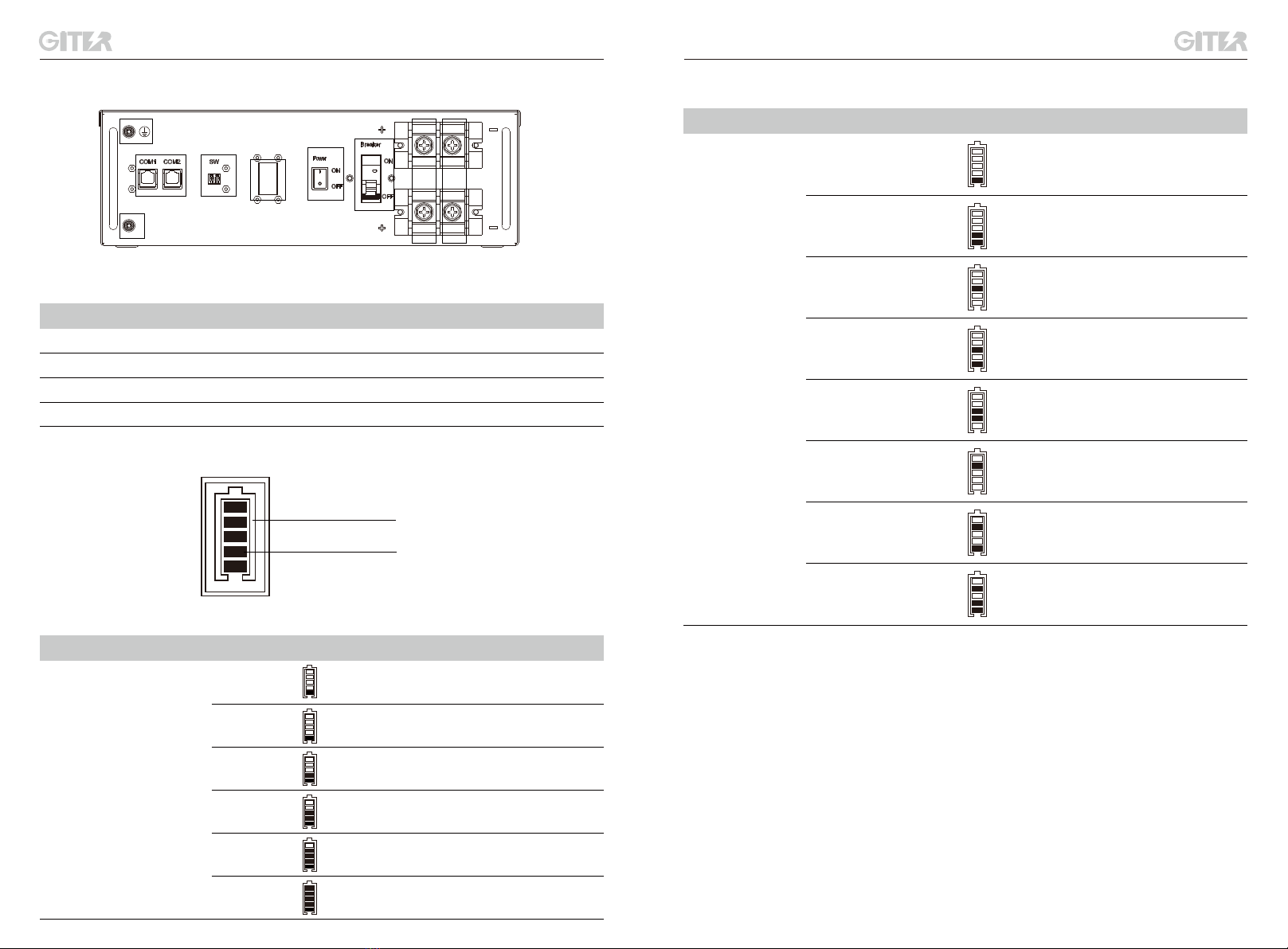
3.1 Power on/off
4.1 Routine maintenance
4.2 Other faults and abnormal phenomena
4.2.1 Unable to turn on
Check all power cables and communication cables carefully.
Common faults and corresponding troubleshooting are listed below.
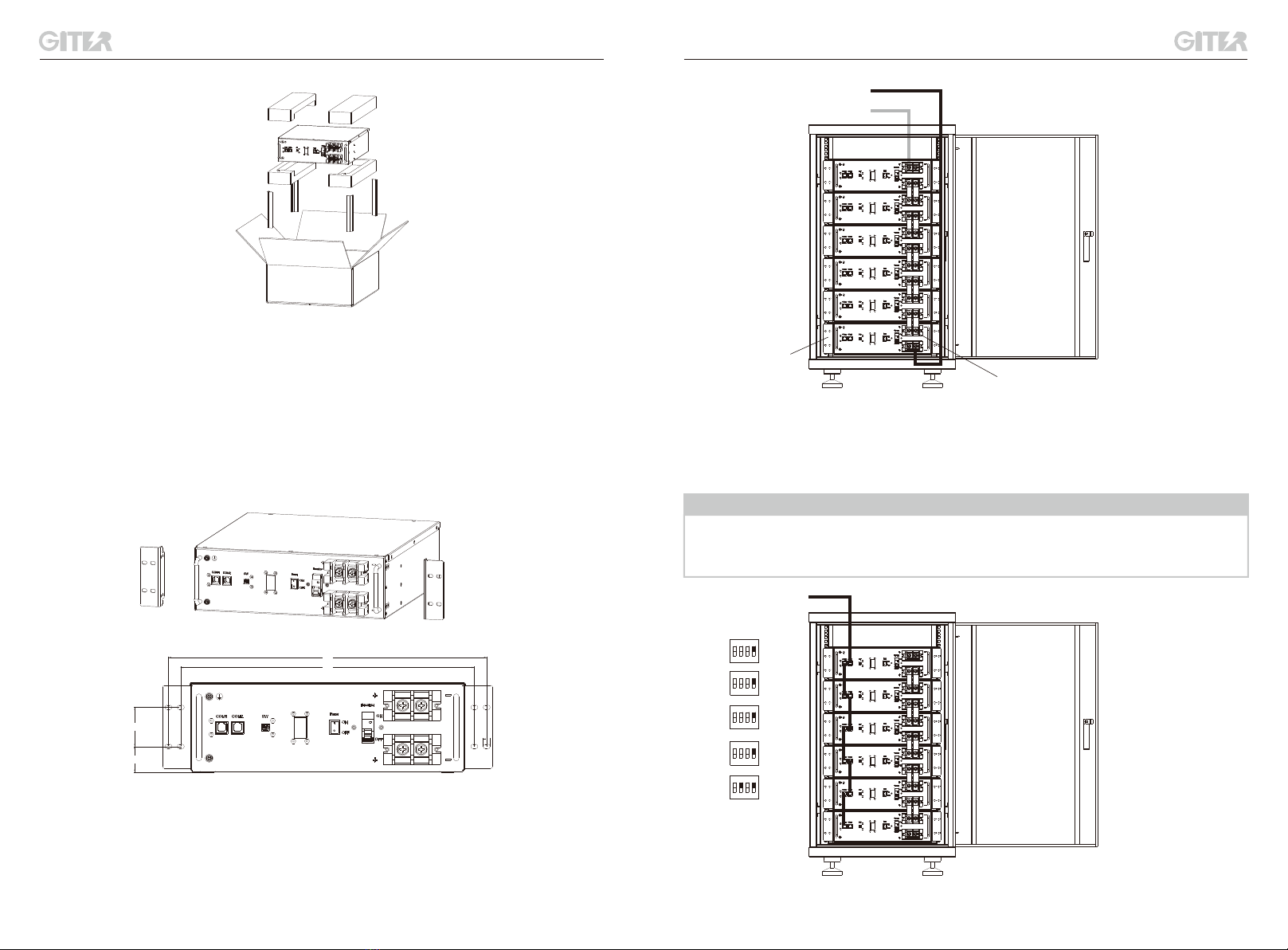
POWER ON: Switch on the Battery Breaker, turn the Power Switch (Rebound button) "ON" and hold
for 1-2 seconds. Then the battery module will activate and the LED display will light up.
POWER OFF: Turn the Power Switch (Rebound button) "ON" and hold for 5 seconds, and the
battery will be turned off.
Batteries should be turned on in the correct order to avoid damage
• Check if the environment situation meet the requirements of the battery.
• Check whether the charging and discharging function of the battery is normal. When one of the
following situations happen, it is necessary to charge the battery in time: the battery protection code
09 appears, the battery is often under charged, and the battery is stored for more than 3 months.
• Check the battery and its appearance, terminals, cables, LED lights, etc.
Fault Troubleshooting Description
Turn on the Power
switch and hold for 2
seconds, while the LED
light isn't on in 3
seconds.
Check if there
resistance when you
turn on the switch.
If the switch has no
resistance, please contact
customer service.
4.2.3 Unable to charge
Fault Troubleshooting Description
The battery cannot be
charged normally while it
is not fully charged with
no LED protection code
nor error code.
1.Check if the battery has
been turned on;
2.Check if the power cables
are connected correctly;
3.Check if the battery breaker
is ON;
4.Check if the ambient
temperature is within the
operating range.
If the battery still cannot
be charged normally after
these steps, please
contact customer service.
4.2.4 Unable to discharge
Fault Troubleshooting Description
The battery cannot be
discharged as it should
while it is still alive with no
LED protection code nor
error code.
1. Check if the battery has been
turned on;
2. Check if power cables are
connected correctly;
3. Check if the battery breaker is
on;
4. Check if the ambient
temperature is within the operating
range;
5. Disconnect the power cables
and test the battery output voltage.
If the voltage is too low, please
charge immediately. If there is no
voltage, please contact customer
service. If the voltage is normal,
you can restart the battery.
If the battery still cannot
be discharged normally
after these steps, please
contact customer service.
4.2.5 No communication between battery and upper controller (if any)
Fault Troubleshooting Description
The upper controller failed
to detect the batteries
1. Confirm if the battery has been
turned on;
2. Check if the power cables are
connected correctly;
3. Check if the communication
cables are connected correctly
and whether they are damaged;
4. Check if the DIP Switch 2 is
set "ON", which is on the farthest
battery away from the upper
controller;
5. Restart the batteries.
If the battery still cannot
be used normally after
following the steps, please
contact customer service.
4.2.2 Shut down immediately after turning on
Fault Troubleshooting Description
Turn on the Power switch and
hold for 2 seconds, while the
LED light goes off again after 8
seconds.
Check if the switch can
bounce back.
If the switch cannot
bounce back, please
contact customer service.