Gitzo GHF2W User manual

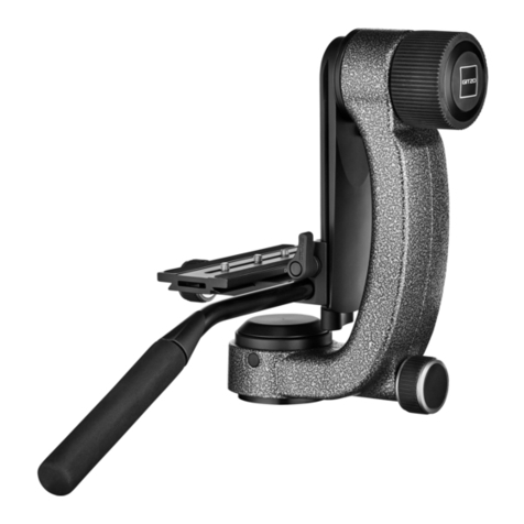
GHF2W
2 way fluid head


GHF2W
2 way fluid head

Instructions/Istruzioni/Gebrauchsanweisung/Mode d’emploi/Instrucciones
43
A
D
E
2
C1
1 2
X
A
B
2
1
C

使用说明 / 사용설명서 / 使用説明書
56
7
2
H
1
F
F
8
H

9 10
11 12 13

14
1615
F
N
2
1

English
FIG. 1 – Assemble Handle Bar
Assemble the handle bar “A” as shown in figure.
The pan bar length can be adjusted by locking the bar with knob “B” at
the desired position. The rosette “X” has teeth to allow the pan bar to be
positioned at various intervals.
FIG. 2 – How to remove the camera plate
Hold the camera plate, loosen screw “C” as shown in the diagram, and
lift the plate out of the quick release adaptor.
FIG. 3 – How to mount the equipment on the plate
To tighten the plate you can use
- a coin “A”
- ex key “E”
- the screw’s flip ring “D”
The plate can be mounted on the camera/lens in different directions.
FIG. 4 – How to mount the equipment on the head
Insert the equipment and plate from above. Tighten knob “C” to lock the
camera securely in place. The quick release adaptor allows the sliding of
the plate when the locking lever is not fully locked, and includes a safety
pin that prevents accidental fallings of the camera.

FIG. 5-6-7-8-9-10-11-12-13-14 – Counter balance system
The head is provided with a spring loaded counter balance system (ON/
OFF, 7 positions) to balance the off centre weight of your equipment. The
head is able to support loads up to 4 kg (8.8 lbs), and the balance system
allows to balance a off centre load up to 2,5 kg (5.5 lbs). The head can
be used with or without counter balance system.
FIG. 5
Without counter balance system the head behaves like a standard fluid head:
1. make sure that the tilt control knob “F” is tightened.
2. with one hand pull out and fully rotate the knob “H” to “OFF” position
(following the arrow).
3. with the other hand hold your equipment and unscrew the knob “F”.
FIG. 6
If you want to use the head with counter balance system, proceed as follow:
- unscrew the knob “F” while holding your equipment in order to prevent
it from suddenly flopping
- move the equipment in order to reach the “zero” position (indicated
by arrow )
FIG. 7 - With the other hand fully rotate the knob “H” to “ON” position
(following the arrow).
FIG. 8 - If the equipment doesn’t move, it means that you have reached
the balance point.

FIG. 9 - If the equipment falls, find the balance point as follow.
1. FIG. 10 - Rotate and pull out the knob “H” to “off” position.
2. FIG. 11 - Rotate your equipment in the opposite direction of the fall.
3. FIG. 12 - Reach the first dash after the “zero” position accordingly to
the direction of the fall (always opposite direction) and rotate the knob
“H” to “ON” position until it locks into position.
4. FIG. 13 - Check if the equipment doesn’t move: it means that you have
reached the balance point.
5. FIG. 14 - If the equipment falls down, repeat the instructions above,
selecting the following position (2nd and 3rd dashes after the ). 3rd
position allows the maximum balance capacity.
FIG. 15 – Remove equipment from the head
FIG. 16 – Use
N Pan control knob: friction and lock (360°)
F Tilt control knob: friction and lock (+90/-60°)


Italiano
FIG. 1 – Montaggio della leva di comando
Montare la leva di comando “A” come mostrato in figura.
La lunghezza della leva di comando può essere regolata bloccando la leva
nella posizione desiderata con la manopola “B”. I denti della rosetta “X”
consentono di sistemare la leva di comando in varie posizioni.
FIG. 2 – Rimozione della piastra per la fotocamera
Tenendo la piastra per la fotocamera, svitare la manopola “C” ed estrarre
la piastra dall’adattatore come mostrato in figura.
FIG. 3 – Montaggio dell’apparecchio sulla piastra
Per fissare la piastra è possibile utilizzare
-una moneta “A”
-la chiave a brugola “E”
-l’anello pieghevole della vite “D”
La piastra può essere fissata alla fotocamera/lente in posizioni diverse.
FIG. 4 – Montaggio dell’apparecchio sulla testa
Montare l’apparecchio e la piastra dall’alto. Bloccare saldamente la
fotocamera sulla testa avvitando la manopola “C”. L’adattatore per piastra
rapida consente lo scorrimento laterale della piastra quando la leva di
bloccaggio non è completamente bloccata ed è dotato di un perno di
sicurezza per evitare cadute accidentali della fotocamera.

FIG. 5-6-7-8-9-10-11-12-13-14 – Sistema di controbilanciamento
La testa è fornita di un sistema di controbilanciamento a molla precaricata
(ON/OFF, 7 posizioni) per compensare il peso sbilanciato dell’apparecchio
in uso. La testa può portare fino a 4 kg di peso, mentre il sistema di
bilanciamento può compensare uno squilibrio fino a 2,5 kg. La testa può
essere utilizzata con o senza il sistema di controbilanciamento attivato
o disattivato.
FIG. 5
Senza il sistema di controbilanciamento la testa si comporta come una
normale testa fluida:
1. assicurarsi che la ghiera di controllo dell’inclinazione “F” sia stretta;
2. con una mano estrarre e ruotare a fondo la manopola “H” in posizione
“OFF” (come indicato dalla freccia);
3. con l’altra mano tenere l’apparecchio e svitare la ghiera “F”.
FIG. 6
Per utilizzare la testa con il sistema di controbilanciamento, procedere
come segue:
- svitare la ghiera “F” reggendo l’apparecchio per impedirne la caduta
- portare l’apparecchio in posizione “zero” (indicata dalla freccia )
FIG. 7 - Con l’altra mano ruotare a fondo la manopola “H” in posizione
“ON” (come indicato dalla freccia).
FIG. 8 - Se l’apparecchio non si muove, significa che è stato raggiunto il
punto di bilanciamento.

FIG. 9 - Se l’apparecchio si inclina, trovare il punto di bilanciamento
come segue.
1. FIG. 10 - Estrarre e ruotare la manopola “H” in posizione “OFF”.
2. FIG. 11 - Ruotare l’apparecchio in direzione opposta a quella di caduta.
3. FIG. 12 - Selezionare il primo valore di compensazione dopo la posizione
“zero” in base alla direzione di caduta (andare sempre nella direzione
opposta) e ruotare la manopola “H” fino a bloccarla su “ON”.
4. FIG. 13 - Verificare che l’apparecchio non tenda a inclinarsi.
Se l’apparecchio non si muove significa che è stato raggiunto il punto
di bilanciamento.
5. FIG. 14 - Se l’apparecchio si inclina, ripetere la procedura descritta in
precedenza selezionando un nuovo valore di compensazione (secondo
o terzo valore dopo la ). La posizione “+/-3” corrisponde al massimo
bilanciamento disponibile.
FIG. 15 – Rimozione dell’apparecchio dalla testa
FIG. 16 – Uso
N Manopola di controllo della panoramica: frizione e blocco (360°)
F Ghiera di controllo dell’inclinazione: frizione e blocco (+90/-60°)


Deutsch
ABB. 1 – Zusammenbau des Schwenkgriffs
Bauen Sie den Schwenkgriff „A“ zusammen, wie in der Abbildung gezeigt.
Zur Einstellung der Schwenkgrifflänge blockieren Sie den Griff mittels
Knopf „B“ in der gewünschten Position. Die Rosette „X“ hat Zähne, damit
der Schwenkgriff in verschiedenen Abschnitten greifen kann.
ABB. 2 – Wie Sie die Kameraplatte entfernen
Halten Sie die Kameraplatte, lösen Sie die Schraube „C“, wie in der Abbildung
dargestellt; nehmen Sie die Platte aus dem Schnellwechseladapter.
ABB. 3 – Wie Sie die Ausrüstung auf der Platte montieren
Zum Anziehen der Platte können Sie Folgendes verwenden
- Münze „A“
- Sechskantschlüssel „E“
- Bügel „D“ der Schraube
Die Platte kann in verschiedenen Richtungen an die Kamera bzw. die
Objektive montiert werden.
ABB. 4 – Wie Sie die Ausrüstung auf den Kopf montieren
Setzen Sie Ausrüstung und Platte von oben ein. Knopf „C“ anziehen, um
die Kamera sicher zu befestigen. Der Schnellwechseladapter gestattet das
Gleiten der Platte, wenn der Verschlusshebel nicht vollständig festgezogen
ist. Ein Sicherheitspin verhindert ein unbeabsichtigtes Herausrutschen der
Schnellwechselplatte samt Equipment.

ABB. 5-6-7-8-9-10-11-12-13-14 – Gegengewichtsystem
Der Kopf ist mit einem gefederten Gegengewichtssystem (ON/OFF, 7
Positionen) ausgestattet. Dieses balanciert außerhalb des Schwerpunkts
befindliche Lasten aus. Der Kopf unterstützt Lasten bis zu 4 kg, das
Gegengewichtssystem balanciert außerhalb des Schwerpunkts befindliche
Lasten bis zu 2,5 kg aus. Der Kopf kann mit oder ohne Gleichgewichtssystem
eingesetzt werden.
ABB. 5
Beim Einsatz ohne Gegengewicht verhält sich der Kopf wie ein Standard-
Fluid-Kopf:
1. Stellen Sie sicher, dass der Neiger-Knopf „F“ fest angezogen ist.
2. Mit einer Hand ziehen Sie den Knopf „H“ heraus und drehen ihn ganz
in die „OFF“-Position (der Pfeilrichtung folgend).
3. Mit der anderen Hand halten Sie Ihre Ausrüstung und lösen Sie den
Knopf „F“.
ABB. 6
Wenn Sie den Kopf mit Gegengewichtssystem nutzen möchten, gehen
Sie vor, wie folgt:
-Lösen Sie den Knopf „F“, während Sie die Ausrüstung festhalten, um ein
unbeabsichtigtes Herausrutschen zu vermeiden
-Bewegen Sie die Ausrüstung in die Null-Position (siehe Pfeil ).
ABB. 7 - Mit der anderen Hand drehen Sie den Knopf „H“ in die „ON“-
Position (dem Pfeil folgend).

ABB. 8 - Wenn sich die Ausrüstung nicht nach hinten oder vorne neigt,
haben Sie den Gleichgewichtspunkt erreicht.
ABB. 9 - Neigt sich die Ausrüstung, finden Sie den Gleichgewichtspunkt,
wie folgt:
1. ABB. 10 - Ziehen Sie den Knopf „H“ heraus und drehen Sie ihn die
„OFF“-Position.
2. ABB. 11 - Drehen Sie Ihre Ausrüstung in die Richtung, die dem Neigen
entgegengesetzt ist.
3. ABB. 12 - Erreichen Sie den ersten Strich nach der „Null“-Position
je nach Fallrichtung (immer in die entgegensetzte Richtung); drehen Sie
den Knopf „H“ in die „ON“-Position, bis er einrastet.
4. ABB. 13 - Prüfen Sie, ob sich die Ausrüstung nicht bewegt: Dies
bedeutet, Sie haben den Gleichgewichtspunkt erreicht.
5. ABB. 14 - Falls die Ausrüstung weiterhin neigt, wiederholen Sie
die oben beschriebenen Schritte und wählen die folgende Position (2.
und 3. Strich nach dem ). Die 3. Position entspricht der maximalen
Gegengewichtskapazität.
ABB. 15 – Entfernen Sie die Ausrüstung vom Kopf

ABB. 16 – Verwenden Sie
N Schwenkregler-Knopf: Friktion und Verriegeln (360°)
F Neiger-Knopf: Friktion und Verriegeln (+90/-60°)

Français
FIG. 1 – Montage de la barre panoramique
Installez la barre « A » comme indiqué sur l’illustration.
La hauteur de la barre panoramique se règle en la verrouillant dans la
position désirée grâce à la molette « B ». La molette « X » est crantée
pour permettre de positionner la barre panoramique à divers intervalles.
FIG. 2 – Comment retirer le plateau rapide
En tenant le plateau rapide, desserrez la vis « C » comme indiqué sur le
schéma et extrayez le plateau en dehors de son support.
FIG. 3 – Comment monter l’équipement sur le plateau
Pour serrer le plateau, vous pouvez utiliser :
- une pièce de monnaie « A » ;
- une clé hexagonale « E » ;
- l’anneau de serrage en demi-lune « D ».
Le plateau peut être monté dans plusieurs sens sur le boîtier/l’objectif.
FIG. 4 – Comment monter l’équipement sur la rotule
Insérez l’équipement et le plateau par le haut. Serrez la molette « C » pour
que l’appareil soit verrouillé de manière sécurisée. Le support du plateau
rapide permet de faire coulisser le plateau lorsque le levier de verrouillage
n’est pas complètement fermé et comporte un ergot de sécurité qui
empêche toute chute accidentelle de votre matériel.
Table of contents
Languages:
Other Gitzo Camera Accessories manuals
Gitzo
Gitzo G0045611 User manual

Gitzo
Gitzo GT2540LLVL User manual

Gitzo
Gitzo GT2540G User manual

Gitzo
Gitzo GH1780QD User manual

Gitzo
Gitzo G1258LVL User manual

Gitzo
Gitzo GT2531 User manual

Gitzo
Gitzo GT1940C User manual

Gitzo
Gitzo GT2940LVL User manual

Gitzo
Gitzo GT2540EX User manual

Gitzo
Gitzo Classic Inter Pro Studex Mk2 G1341 G1341 User manual

Gitzo
Gitzo GT0531 User manual

Gitzo
Gitzo GM2560T User manual

Gitzo
Gitzo GT2531LVL User manual

Gitzo
Gitzo GT1531 User manual

Gitzo
Gitzo GT3531S User manual

Gitzo
Gitzo GT2541G User manual

Gitzo
Gitzo GT2941LLVL User manual

Gitzo
Gitzo GT3531 User manual

Gitzo
Gitzo Mini Traveler User manual
Gitzo
Gitzo GT2540 User manual