Operating Manual for Navi-
gation Lights Series
AQUA SIGNAL 30
Betriebsanleitung für Navi-
gationsleuchten Serie
AQUA SIGNAL 30
Instructions de service pour
feux de navigation série
AQUA SIGNAL 30
Navigation Lights with LED technology Navigationsleuchten mit LED-Technik Feux de navigation en technologie LED
Supply: 12V/24V DC ±20%.
Consumption: approx- 1,0 W
2 Mile allround white LED light
Stromversorgung: 12V/24V DC ±20%.
Leistungsaufnahme: ca. 1,0 W
2 Seemeilen rundum weiß LED Leuchte.
Alimentation: 12V/24 DC ±20%.
Consommation: ca. 1,0 W
Visibilité 2 mn
These lights are in accordance with the international IMO
regulations for collision avoidance from 1972 / COLREG’s
1972.
Diese Navigationsleuchten entsprechen den internationalen
Bestimmungen der IMO, Kollisionsverhütungsregeln 1972 /
COLREG’s 1972.
Ces feux de navigation sont conformes aux règlements
internationaux IMO contre les abordages en mer de 1972 /
COLREG’s 1972.
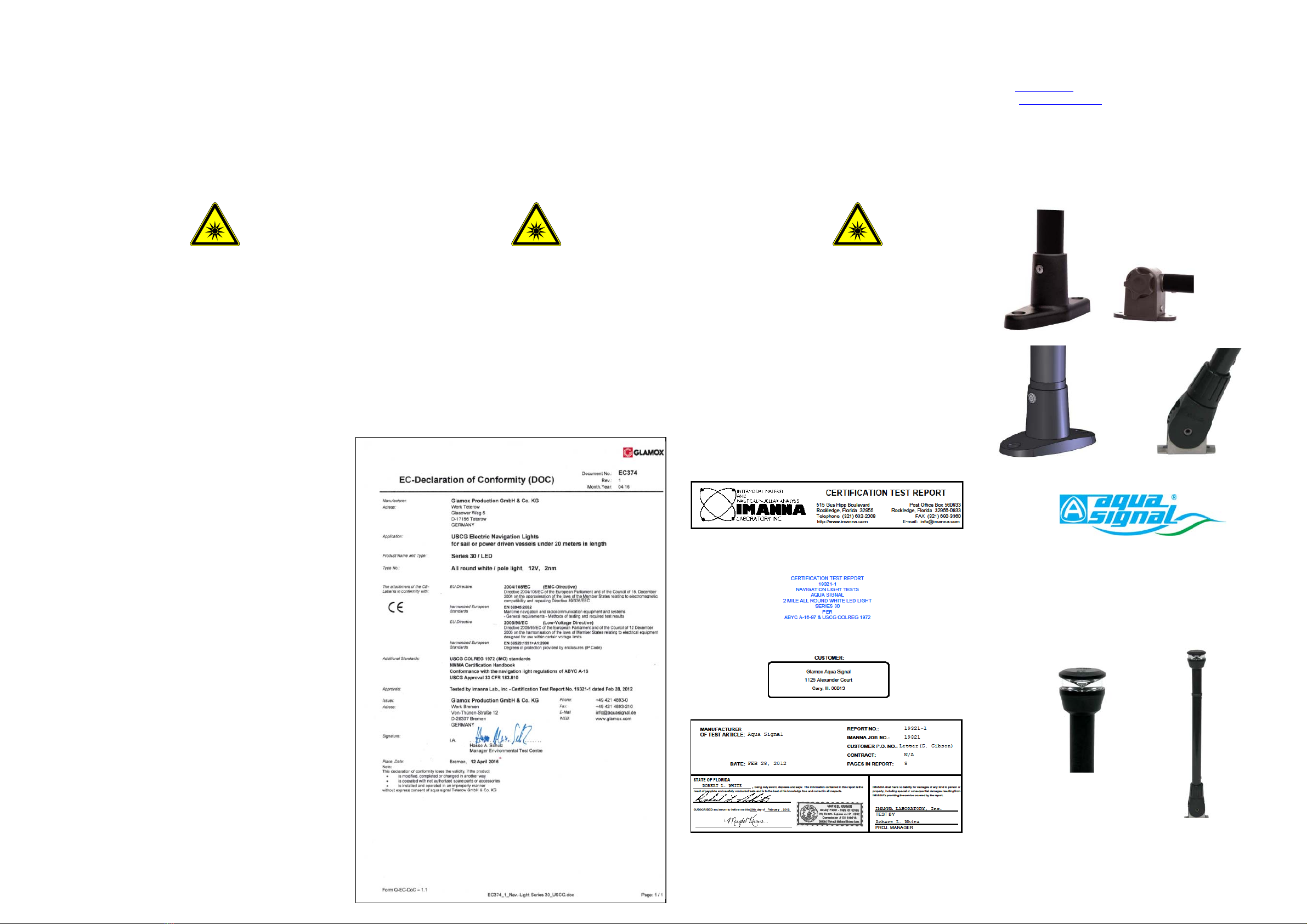
Approvals:
(i) USCG Approval 33 CFR 183.810 - COLREG´s USCG /
IMO for vehicles of 12 to 20 metres length
(ii) ABYC A-16-97 for sailing and motor boats below 20
metres length
(iii) Tested by IMANNA Lab. Inc. Test report 19321-1,
Feb 28 2012
Zulassungen:
(i) USCG Approval 33 CFR 183.810
COLREG´s USCG / IMO für Fahrzeuge zwischen 12 m und
20 m.
(ii) ABYC A-16-97 für Segel- und Motorboote unter 20 m.
(iii) Tested by IMANNA Lab. Inc. Test report 19321-1,
28.02.2012.
Homologations:
(i) Approbation USCG 33 CFR 183.810
COLREG´s USCG / IMO pour véhicules dont la taille est
comprise entre 12 m et 20 m
(ii) ABYC A-16-97 pour bateaux à voile et à moteur avec
une taille inférieure à 20 m.
(iii) Testé par IMANNA Lab. Inc. Rapport de test : 19321-1,
28 février 2012
Regulations
For all ships the rules set forth in Annex 1 to the Interna-
tional Regulations for Preventing Collisions at Sea - Posi-
tioning and Technical Details of Lights and Signalling
Shapes - must be adhered to. The technical data regarding
horizontal and vertical positioning and spacing of the naviga-
tion and signalling lights laid down in these mounting in-
structions do apply to all ships irrespective of their flag.
Vorschriften
Für alle Schiffe müssen die in Anhang 1 ausgeführten
Vorschriften der Kollisionsverhütungsregeln – Platzierung
und technische Details für Lichter und Signalkörper – ein-
gehalten werden. Die technischen Daten in Bezug auf die
horizontale und vertikale Platzierung und die Abstände der
Navigations- und Signallichter, die in dieser Betriebsanlei-
tung beschrieben sind, gelten für alle Schiffe, unabhängig
von ihrer Flagge.
Règlements
Pour les navires étrangers ANNEXE 1 - formes, position et
détails technique des feux, les règlements internationaux
contre les abordages en mer de 1972 doivent être appli-
qués.
Les caractéristiques techniques concernant la position
horizontale et verticale, ainsi que l’espacement des feux de
navigation, décrites dans nos instructions de montage,
s’appliquant aux navire de toutes nationalités.
Mounting Instructions
The function of the navigation lights can only be assured
and be in accordance with the regulations if the following
points are adhered to:
For correct positioning of the navigation lights on board the
collision regulations 1972 /COLREG’s 1972 have to be
followed.
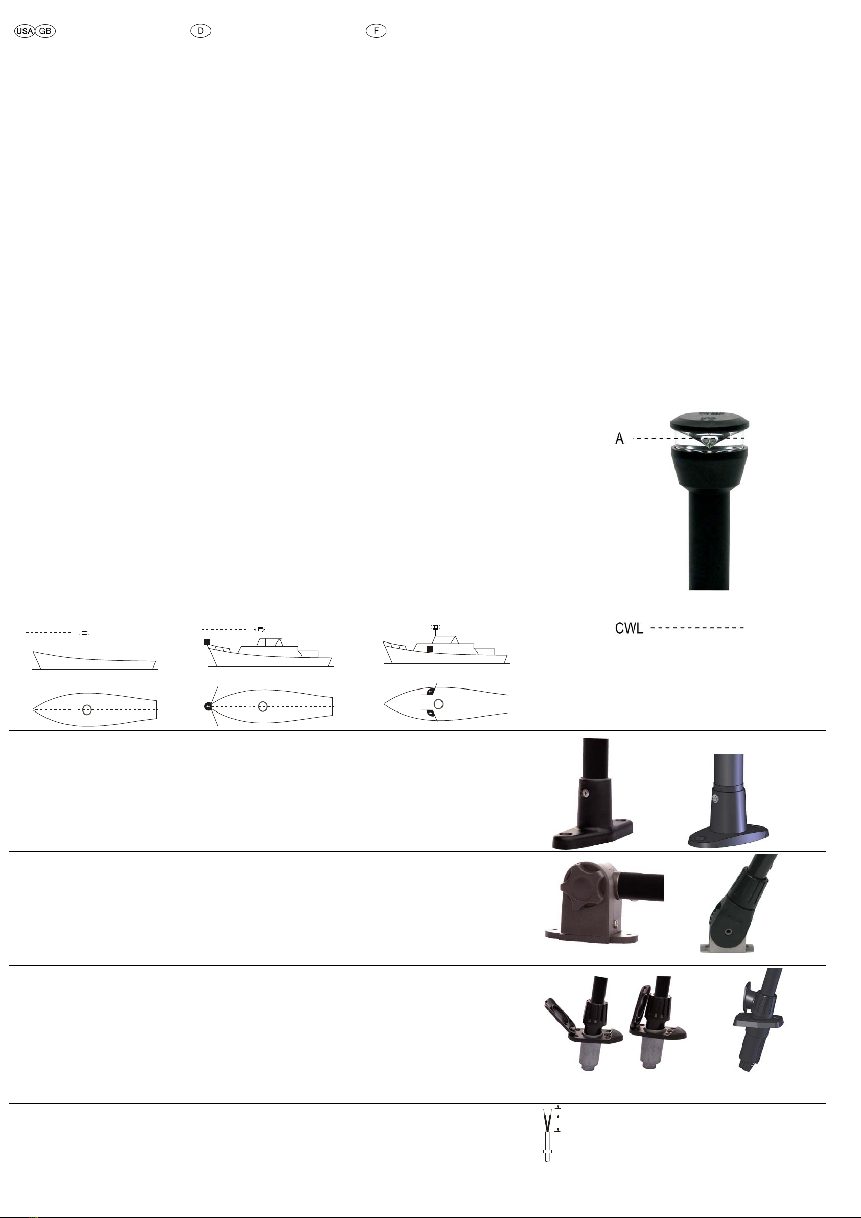
The navigation lights must be positioned on and above the
keel line e.g. parallel to it. Their horizontal symmetrical level
(A) must be parallel to the construction water line (CWL)
(4).
The light cannot be obstructed by parts of the boat or pas-
sengers. Their position may not be changed while in use.
Mounting up side down is not allowed.
Anbauanweisung
Die Funktion der Navigationsleuchten ist nur dann gesichert
und den Regeln entsprechend, wenn beim Anbau und der
Wartung folgende Punkte beachtet werden: Die korrekte
Positionierung der Navigationsleuchten an Bord ergibt sich
aus den Kollisionsverhütungs-Regeln 1972 / COLREG’s
1972. Die Navigationsleuchten müssen in und über der
Kiellinie bzw. parallel dazu angebracht werden.
Ihre horizontale Symmetrieebene (A) muss parallel zur
Konstruktionswasserlinie (CWL) liegen (4).
Der Lichtaustritt darf nicht durch Teile des Fahrzeuges oder
durch an Bord befindliche Gegenstände oder Personen
verdeckt werden. Ihre Stellung zum Fahrzeug darf sich
während der Betriebsdauer nicht verändern.
Eine Montage über Kopf ist unzulässig.
Instructions de montage en général
La bonne fonction des feux de navigation et l’accord avec
les règlements peuvent seulement être assurer si les points
suivants sont suivi.
Pour le positionement correct des feux à bord il faut suivre
les règlements internationaux contre les abordages en mer
de 1972 / COLREG’s 72.
Les feux doivent être montés sur ou en parallèle à la ligne
de quille. Leur plan horizontal (A) devra être parallèle à la
ligne de flottaison (CWL) (4).
Leur position par rapport au navire ne devra pas être chan-
gée pendant leur service.
Un montage inversé n’est pas autorisé.
Descriptions Pole light series 30
Angle: 360° white
visibility 2 nm
Kurzbeschreibung Stableuchte Se-
rie 30
Ausstrahlungswinkel: 360 ° weiß
Tragweite 2 sm
Descriptions réduites série 30
Secteur horizontal : 360°blanc
Visibilité 2 mn
A
CWL
<7 m
< 23’
Sw30
Sw30
max. 7 kn
(1)
A
CWL
TD
<12 m
< 65’
Sw30
Sw30
(2)
A
CWL
<12 m
< 65 ‘
SBb
SBb
Sw30
Sw30
(3)
Assembly with fixed foot
Place foot on assembly area, adjust and mark the bore
holes for the screws with a scriber in the centre. For
through-bolts arrange corresponding bores.
Guide the connection cable through an additional bore and
screw torch to the assembly area. Observe correct
positioning of seal ! Tighten fixing screws !
Montage bei einem festem Fuß
Den Fuß auf der Montagefläche aufsetzen, ausrichten und
die Bohrungen für die Schrauben mit einer Reißnadel in der
Mitte markieren. Bei Durchgangsschrauben entsprechende
Bohrungen setzen.
Das Anschlusskabel durch eine weitere Bohrung führen und
die Stableuchte auf der Montagefläche verschrauben. Auf
eine korrekte Lage der Dichtung achten! Befestigungs-
schrauben festziehen!
Montage sur pied fixe
Placer le pied sur la surface de montage, le mettre dans la
position adéquate, puis marquer les alésages prévus pour
les vis au centre, à l’aide d’une pointe à tracer. Effectuer des
alésages appropriés si vous utilisez des vis traversantes.
Faire passer le câble d'alimentation à travers un autre trou,
puis visser le tube fluorescent à la surface de montage.
Faire de telle sorte qu’il y ait un état d'étanchéité correct !
Serrer les vis de fixation à bloc !
Assembly with jointed foot
Place foot on assembly area, adjust and mark the bore
holes for the screws with a scriber in the centre. For
through-bolts arrange corresponding bores.
Guide the connection cable through an additional bore and
screw pole light to the assembly area. Observe correct
positioning of seal ! Tighten fixing screws !
Montage bei einem Fuß mit Gelenk
Den Fuß auf der Montagefläche aufsetzen, ausrichten und
die Bohrungen für die Schrauben mit einer Reißnadel in der
Mitte markieren. Bei Durchgangsschrauben entsprechende
Bohrungen setzen.
Das Anschlusskabel durch eine weitere Bohrung führen und
die Stableuchte auf der Montagefläche verschrauben. Auf
eine korrekte Lage der Dichtung achten! Befestigungs-
schrauben festziehen!
Montage sur pied avec joint
Placer le pied sur la surface de montage, le mettre dans la
position adéquate, puis marquer les alésages pour les vis au
milieu à l’aide d’une pointe à tracer. Effectuer des alésages
appropriés si vous utilisez des vis traversantes.
Faire passer le câble d'alimentation à travers un autre trou,
puis visser le tube fluorescent à la surface de montage.
Faire de telle sorte qu’il y ait un état d'étanchéité correct !
Serrer les vis de fixation à bloc !
Assembly for foot with plug-in light
Place seal on assembly area, adjust and mark the neces-
sary bore holes for the screws with a scriber in the centre. In
case of a tilted assembly surface widen bores if
necessary.
After boring assemble the inset deck foot and screw to the
assembly area.
Observe correct positioning of seal ! Tighten fixing screws !
Montage bei einem Fuß mit steck-
barer Stableuchte
Die Dichtung auf der Montagefläche aufsetzen, ausrichten
und die notwendigen Bohrungen mit einer Reißnadel in der
Mitte markieren. Bei einer Neigung der Montagefläche ist die
Bohrung ggf. aufzuweiten.
Nach dem Bohren ist der versenkte Decksfuß einzubauen
und auf der Montagefläche zu verschrauben.
Auf eine korrekte Lage der Dichtung achten! Befestigungs-
schrauben festziehen!
Montage sur pied avec tube fluo-
rescent enfichable
Placer le pied sur la surface de montage, le mettre dans la
position adéquate, puis marquer les alésages pour les vis au
milieu à l’aide d’une pointe à tracer. Dans le cas d’une
inclinaison de la surface de montage, l’alésage doit être
éventuellement élargi.
Après le perçage, le pied de pont noyé doit être installé et
vissé à la surface de montage.
Faire de telle sorte qu’il y ait un état d'étanchéité correct !
Serrer les vis de fixation à bloc !
Electrical installation for the pole
light
All navigation lights are pre-fitted with cables and do not
have to be disassembled. Connect the red cable to the +
pole, and the black cable to the - pole.
Elektrischer Anschluss der Stab-
leuchte
Die Stableuchte ist vorverkabelt und braucht für die Montage
nicht zerlegt zu werden.
Das rote Kabel an den + Pol, das schwarze Kabel an den
- Pol anschließen.
Installation électrique du tube fluo-
rescent
Le tube fluorescent est précâblé et ne doit pas être démonté
lors du montage.
Relier le câble rouge au pôle positif et le câble noir au pôle
négatif.
35
mm
5
(4)
Series 30
22 Series 30/20
Series 30
22 Series 30/20
Series 30
22 Series 30/20