4.3 ELECTRICAL INSTALLATION - SETTINGS
Address settings:
1. Each unit (searchlight or panel) must have its own unique address.
Panels and searchlights have separate address spaces, i.e. a
panel with setting ‘2’ does not interfere with a searchlight set to
address ‘2’.
2. The addressed units (panels and searchlights) can be placed freely
along the bus, they don’t have to be placed according to their ad-
dress or in any special order.
3. The address of searchlights are normally pre-set from factory. See
chapter “changing address on searchlight” if changes are needed.
The address can also be hardwired by the address-rotary switch in
the connection box.
4.4 STARTUP OF SYSTEM
1. Check that all connections are correct and no short-circuits or
breaks. Check all 230VAC supply lines. Also check the 24VDC
supply to the panels and other control modules.
2. Turn on power first to the searchlight motor units, then the xenon
power supplies, and at last the 24VDC supplies to the panels. If
the panels are powered from separate supplies, then first apply
power to the slave panels, then to the master panel. Check visu-
ally that each searchlight makes a positional scan right after the
master panel is powered up. The master panel should now find all
searchlights and panels, and be able to communicate with them.
3. Check movement and light on /off of all searchlights.
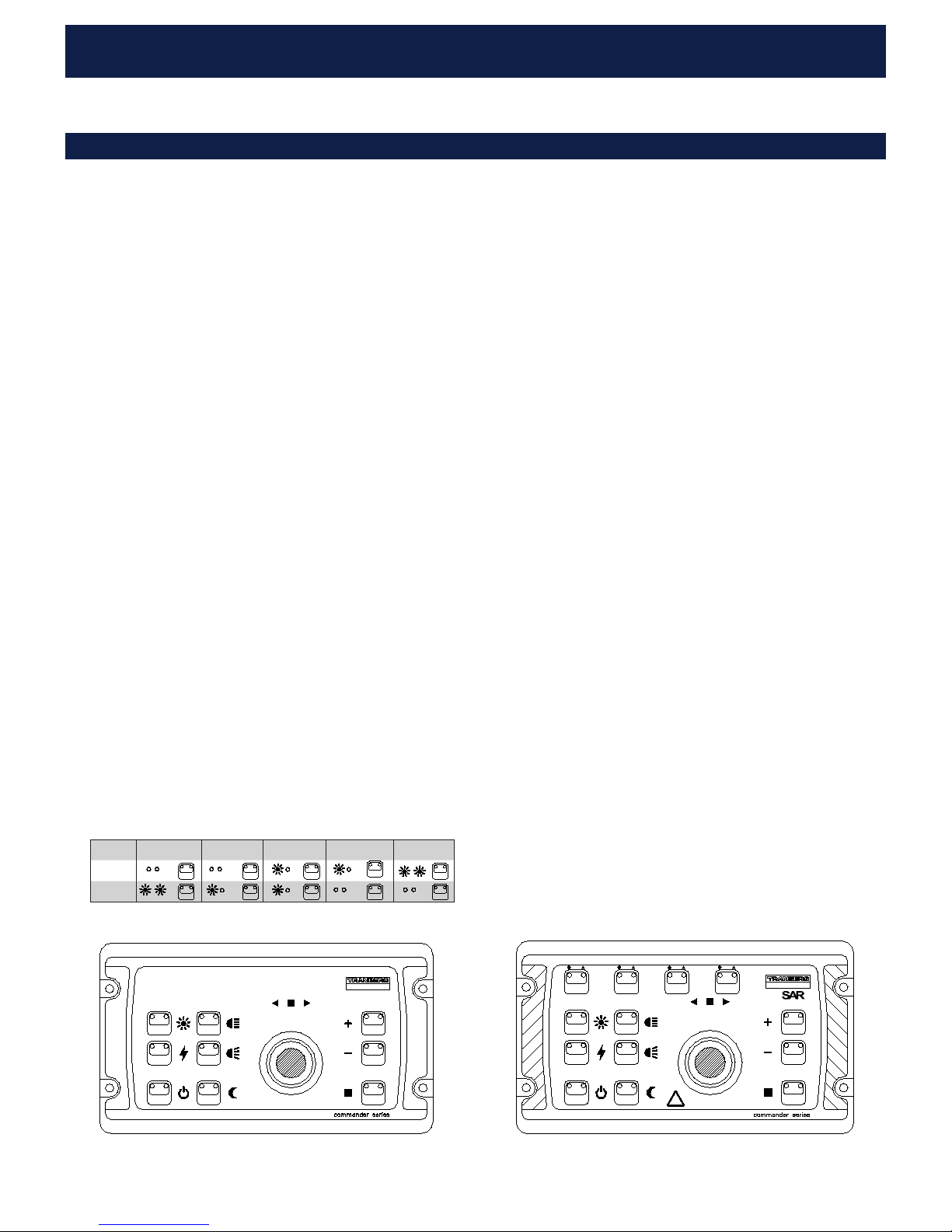
5.1 IDENTIFYING THE MASTER PANEL
For the following special procedures, the master panel need to be
identified.
The master panel can be recognized by the yellow indicator in the
power button. When you turn off power by pressing this button, the
yellow indicator will be continuously lit in the master panel. It will blink
slowly (1 sec. on, 1 sec off) on a slave panel.
5.2 RE-SCAN OF NODES CONNECTED TO THE BUS
If necessary, the master panel can do a bus scan when powered up
using the following procedure:
(Note: Do not operate or use any panels or searchlights during this
procedure. Ensure that all are powered up.)
1. Turn off the master panel using the power button. Release the but-
ton. The backlight will turn off.
2. Press and hold the power button for at least 5 seconds.
3. While holding the power button, press and release the second se-
lect button (marked ‘2/6’ (2613) or ‘B’ (2614) ). (Repeat if neces-
sary, until backlight turns on).
4. The panel backlight will now turn on, and it will start the scanning
of the bus (it takes a couple of seconds).
5. Release the power button.
6. When the scan process is finished, the panel will show which
searchlights are present on the bus by fast flashing the corre-
sponding leds on the select buttons (upper row).
7. Turn on the panel by using the power button as usual.
8. Repeat the procedure if necessary.
5.3 ALTERNATIVE RE-SCAN PROCEDURE
FOR PANELS DELIVERED FROM APRIL 2009 AND ONWARDS:
If necessary, the master panel can do a bus scan when powered up
using the following procedure: A panel can do both this alternate
re-scan procedure as well as the previous procedure (ch. 5.1).
(Note: Do not operate or use any panels or searchlights during this
procedure. Ensure that all are powered up.)
1. Set all panels to standby (“turn off”) by using the on/stdby button.
The backlight will turn off. Locate the master panel (see ch. 3.2),
and turn it on again.
2. Press and hold both speed buttons (‘fast’ and ‘slow’) for at least
5 seconds.
3. On the 2613 and 2614 panels, the indicators in the ‘searchlight
select’ buttons will start flashing in sequence. On the 2612 panels,
the indicators in the speed buttons will flash in sequence. Release
the speed buttons.
4. The sequential flashing will last for a couple of seconds, as long as
the scanning of the bus is performed. When the flashing is finished,
the system is ready for use.
5. Repeat the procedure if necessary.
4 INSTALLATION 5 SPECIAL PROCEDURES
CABLING - SEARCHLIGHT MAINS (230VAC):
For halogen searchlights both power to the lamp as well as power to
the motor unit are supplied through the same cable. Dimension the
cable and fusing according to the wattage of the lamp. Note that halo-
gen lamps have a large inrush current at power-up (due to low filament
resistance when cold), so a slow fuse with same rating, or a fuse with
a higher rating is recommended.
600A105512
1
2
3
4
5
6
7
8
RJ-45
A
Ref
Ref
B
RJ-45
1
2
3
4
5
6
7
8
A
Ref
Ref
B
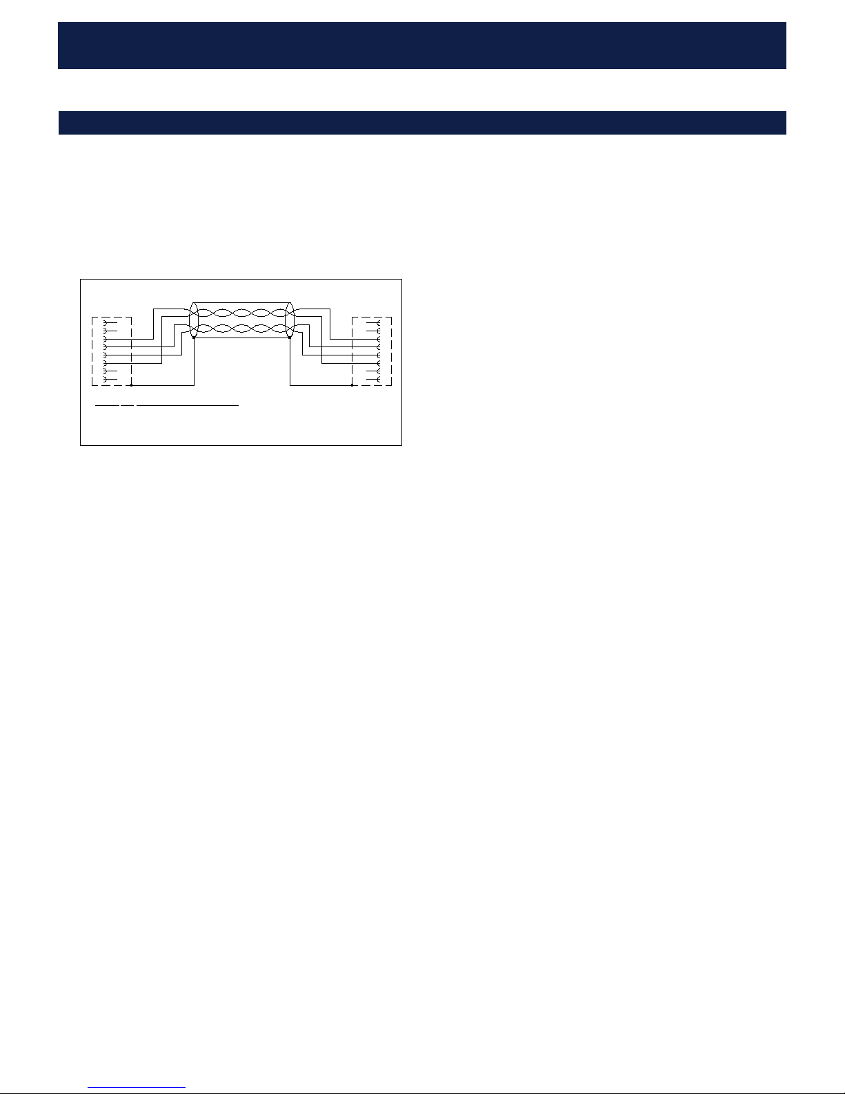
Shield Shield
Cable RS-485
TIA 568-A: TIA 568-B:
White/Orange White/Green
Orange Green
Blue Blue
White/Blue White/Blue
Pin:
3
6
4
5
Signal:
A
B
Ref
Ref
Use twisted pair cable with screen.
Characteristic impedance:
100-250ohm
Pin 1,2,7,8: Not connected
Connections, communication cable
NOTE1:
Keep communication cables away from all power lines.
NOTE2:
Treat / regard Shield/Reference as a signal. It shall under no circum-
stance be connected to Ground or other Protective Earth potentials.
See technical data for details of communication interface.