Page 4
IMPORTANT NOTE: PLEASE ENSURE THAT ALL RELEVANT PERSONNEL READ THE POINTS LISTED WITHIN THIS LEAFLET AND THAT A COPY
IS GIVEN TO STAFF INVOLVED WITH THE INSTALLATION AND MAINTENANCE OF THIS PRODUCT.
SAFETY NOTE: PLEASE REFER TO ‘THE MANUAL HANDLING OPERATIONS REGULATIONS 1992’ DURING HANDLING.
.
AND GLENWOOD™ ARE TRADEMARKS OR REGISTERED TRADEMARKS OF GLASDON GROUP OR
ITS SUBSIDIARIES IN THE U.K. AND OTHER COUNTRIES
A planned maintenance schedule or regular inspection is
recommended, replacing components as necessary.
Replacement components are available direct from GLASDON.
GLASDON cannot be held responsible for claims arising from incorrect
installation, unauthorised modications or misuse of the product.
© Copyright April 2019
Glasdon UK Ltd reserve the right to alter specications without prior notice.
Stock No. C000/0525 - DWG No. 11B-055-17 Issue 1 - April 2019
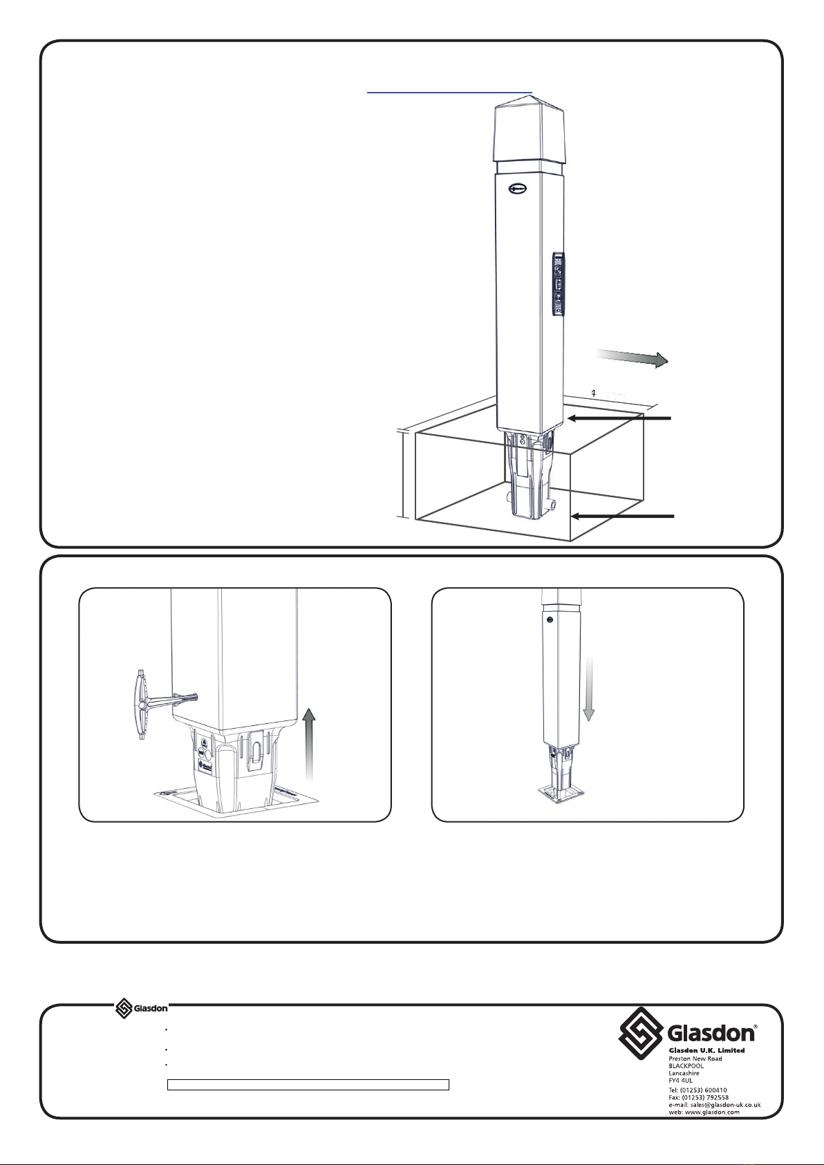
1. Check for buried services before starting
excavations.
2. Mark out and prepare a hole 400mm x
400mm x 315mm deep.
4. Once the post is positioned correctly pour
concrete into the prepared hole to the
ground level.
4. Ensure the post remains vertical during
the concrete setting period. Leave to set.
5. Should block paving be required reduce
the height of the concrete accordingly to
allow the paving to be sited at ground level.
3. Place a small amount of gravel or sand in
the base of the prepared hole and position
post into the hole. Add/remove gravel as
required to help position the post at the
correct height.
-Ensure the top of the post stem is level with
the ground.
-Ensure the post is vertical with the use of a
spirit level.
-Ensure the post is orientated correctly with
regard to the retroreective banding and
the site requirements. (i.e. Red reector faces
oncoming trafc on the near-side and white
reector faces on coming trafc on the off-
side).
Glenwood 170 Extended Base Installation Instructions
315mm
400mm
4
00m
m
Spirit
Level
Layer of
Gravel or
Sand
Ground
Level
C
arriageway (UK)
See our website for a video guide - www.glasdon.com
Glenwood 170 Socketed Post Operating Instructions
To remove the post, rmly push the key into
the track and lift to remove the post from the
socket.
To lock the post in place, drop it into the
socket. Ensure the post is orientated correctly
with regard to the retroreective banding
and the site requirements (i.e. red reector
faces oncoming trafc on the near side and
white reector faces oncoming trafc on the
off-side). Test by attempting to pull the post
from the socket.
2.1.