Glasdon JUBILEE DUO 220 Manual

OPERATING & INSTALLATION MANUAL
IMPORTANT NOTE:
The bin must be sited on level ground to ensure correct alignment of the doors and body. If you are
not using Glasdon xings you must ensure that 50mm diameter washers are used in order to secure
the bin when ground xing.
Ensure that all relevant personnel read the points listed within this leaet and that a copy is given to
sta involved with the installation and maintenance of this product.
1 of 8
GLASDON JUBILEE™ DUO 220

OPERATING & INSTALLATION MANUAL
CONTENTS PAGE
SECTION 1 OPERATING THE BIN
Open/Closing Keyed Version 3
Open/Closing Keyless Version 3
Removing Liner/Using Sack Retention 3
Inserting/Removing Bait Box 4
Inserting/Removing Poster 4
Removing/Replacing Aperture Panels 4
Ashtray Emptying 5
SECTION 2 CLEANING
Bin 5
Liner Tray 5
SECTION 3 INSTALLATION / FIXING INSTRUCTIONS
Concrete Foundation Fixing Kit 6
Paving Slab Fixing Kit 6
Concrete-In Anchor (Adjustable Depth) Fixing Kit 7
2 of 8

OPENING/CLOSING - KEYED VERSION
3 of 8
1. 2. 3. 4.
Place foot into base recess, on
the left hand door as shown.
Insert key into keyhole. Turn
key anticlockwise until it stops.
Using the foot recess and the
key, lift the door and allow it
to pivot open. Lift and pull to
open the second door.
Slam to shut.
Note: Right hand door must be
shut rst before slamming the
left hand door shut.
OPENING/CLOSING - KEYLESS VERSION
1. 2. 3. 4.
Place foot into base recess as
shown.
Push pedal upwards with toe
cap to operate foot pedal.
Using the top of the door and
foot to assist, lift door and allow
it to pivot open. Lift and pull to
open the second door.
Slam to shut.
Note: Right hand door must be
shut rst before slamming the
left hand door shut.
REMOVING LINER/USING SACK RETENTION (OPTIONAL EXTRA)
1. 2. 3. 4.
Remove liner by sliding out of
bin.
Release elasticated sack band
away from body for safety.
Insert plastic sack. Reposition elasticated sack band
to secure plastic sack.
SECTION 1 - OPERATING THE BIN

4 of 8
REMOVING/INSERTING LINER TRAY AND FITTING BAIT BOX
1. 2. 3.
Remove the liner tray by
removing the xings with a
4mm Allen key.
Insert bait box into position
with the aperture facing the
rear of the bin.
Reposition liner tray into bin
base, insert xings and tighten
with the Allen key to secure.
Glasdon Jubilee Duo 220L Bin.
Max. size bait box 280 x 280 x
130mm
INSERTING/REMOVING POSTER
1. 2. 3.
Remove all six wingnuts
and washers from the inside
of the bin by unscrewing
anticlockwise.
From outside the bin, remove
the frame and insert/replace
poster behind the clear panel.
Place frame back into position
and tighten wingnuts from
inside the bin to secure.
IMPORTANT NOTE: Do not
over-tighten wingnuts
Accepts laminated A4 paper/
card with a visible viewing area
of 277mm x 191mm
REMOVING/REPLACING APERTURE PANELS
1. 2. 3. 4.
Using an M8 security Allen
key loosen the screws on the
aperture. Unscrew and remove
all x3 screws and washers.
From outside the bin, pivot the
panel forward from base then
pull downwards to remove.
To insert a panel, position top
bosses of the panel into holes in
the body then push panel into
position.
Replace washers and screws
and tighten with an M8 security
Allen key to secure.

5 of 8
ASHTRAY OPERATING INSTRUCTIONS
1. 2. 3. 4.
Open both doors as detailed
previously. (‘Opening/Closing’)
Using the handle, slide the
ashtray liner out. Use other
hand to support the liner.
Empty contents of the liner. Slide ashtray liner back into the
bin compartment making sure
the handle is facing towards
you.
SECTION 2 - CLEANING
CLEANING YOUR BIN
We would recommend a warm pressure wash with soap or alternatively hand wash with 10% solution of mild detergent in warm water
using a soft bristle brush followed by a rinse with clean water.
Felt tip marker pens or paint may be removed from the Durapol using a proprietary grati remover. Carefully follow the instructions,
particularly the guidelines covering safety. Ensure that all traces of chemicals are removed once the grati has been erased, then clean
as detailed above.
Caution
Many grati removers can damage banding and stickers. Use only on the areas of the Durapol aected and do not use on the banding
or graphics.
CLEANING LINER TRAY
To aid cleaning, the liner tray can be removed to empty any debris that may have fallen out of the liner. Reservoirs in the liner tray can
be easily emptied and wiped clean.
SAFETY NOTE:
Liner or contents may be hot so caution must be used when emptying the ashtray.
Appropriate safety gloves and PPE should be worn.
MAINTENANCE
A planned maintenance schedule of regular inspection is recommended and components replaced when necessary.

SECTION 3 - INSTALLATION / FIXING INSTRUCTIONS
6 of 8
KIT CONTENTS:
- 50mm Washer
- Concrete Fixing Bolt (M10x120mm) c/w Nut and Washer x4
- Pavement Fixing Bolt (M10x75mm) c/w Nut and Washer x4
TOOLS/EQUIPMENT REQUIRED:
- Spanner / Tube Spanner 17mm
- Appropriate Electric Drill
- M10 Masonry Drill Bit
IMPORTANT SAFETY NOTE:
To ensure a secure and robust installation the bin should be sited onto a sound concrete foundation
and the 50mm diameter washer must be used. We strongly recommend that the bin is NOT installed
onto tarmac or block paved areas.
Please refer to the ‘Manual Handling Operations Regulations 1992’during the handling of the product
and materials used for the installation.
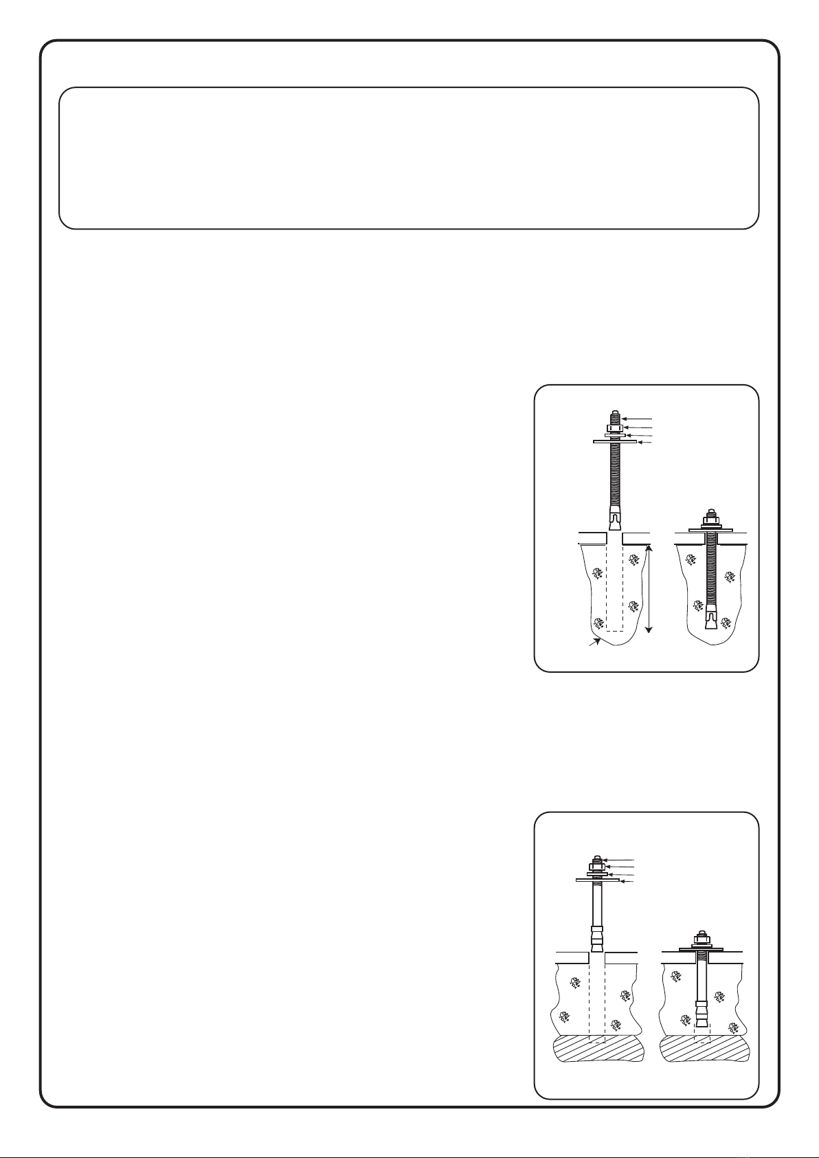
CONCRETE FIXING KIT
INTO PREPARED CONCRETE FOUNDATION
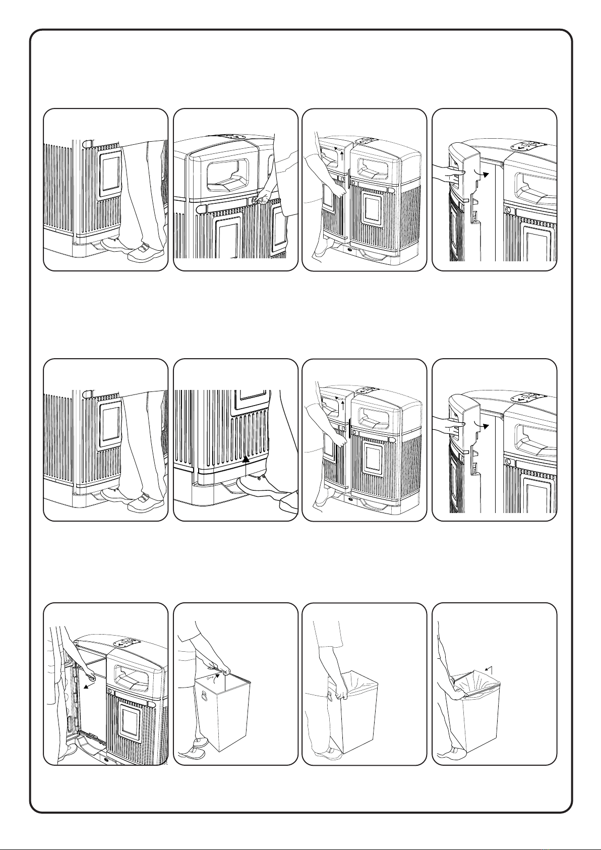
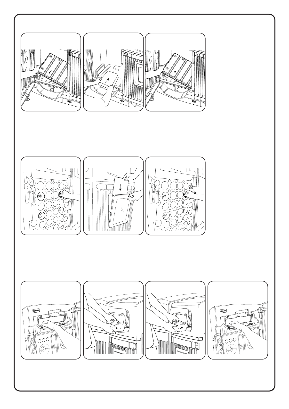
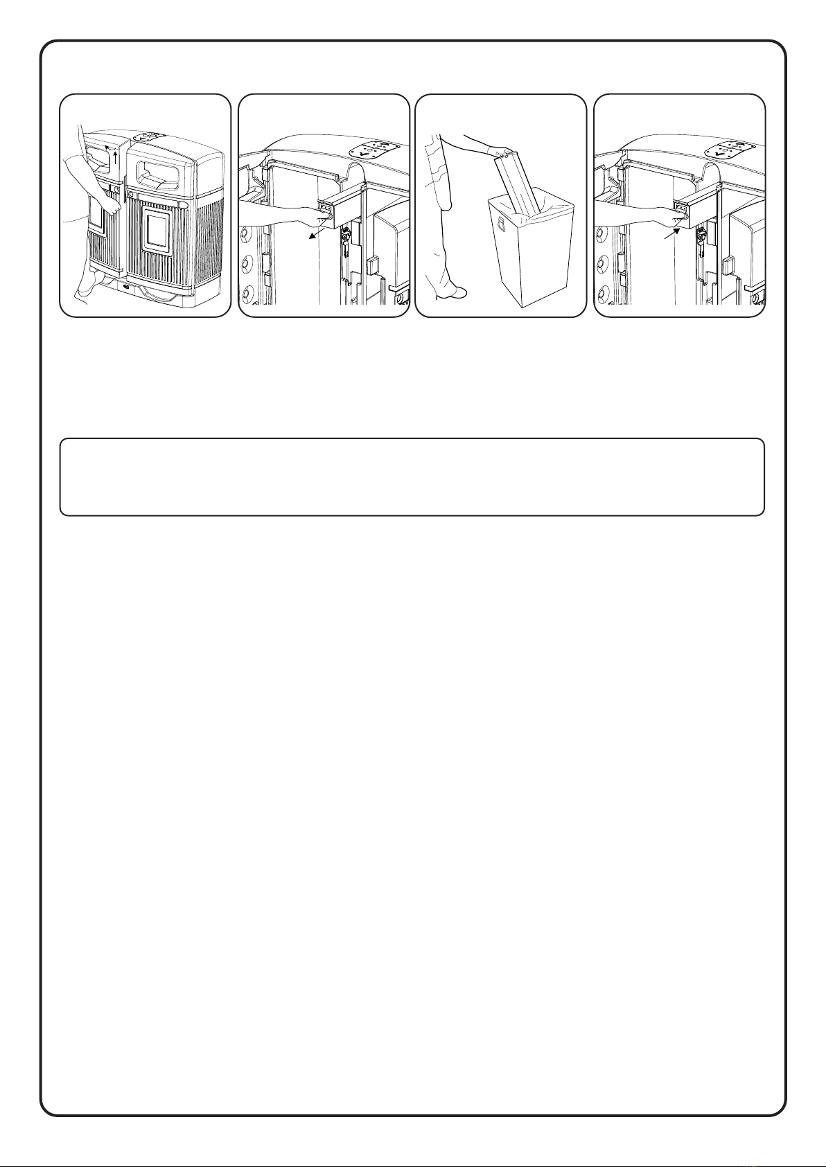
For ease of access the liner tray can be removed, please refer to Section 1 -
Removing/Inserting Liner Tray and Fitting Bait Box
Distance from the edge of the foundation to centre of ground bolt to be no
less than 110mm
Permanently sited onto a prepared concrete ground site (20-30Nmmsq) utilising x4
M10x120mm ground xing bolts.
1. Position bin into siting area ensuring it is in the correct distance away from the edge
of the concrete and is in the correct orientation with regard to the apertures.
2. From the inside of the bin mark hole positions onto the concrete through the xing
holes in the base of the bin with a 10mm diameter masonry drill. Remove the bin.
3. Using a 10mm diameter masonry drill bit, drill and clean out anchor holes to a mini-
mum depth of 130mm. Position bin back over the drilled holes.
4. Assemble the ground bolts as shown in the diagram opposite ensuring only 2 or 3
threads are showing above the nut. Drive the ground bolts through the holes in the
base of the bin and into the holes in the concrete.
5. Tighten nut with correct spanner until xings are secure. Max recommended torque
setting - 20lbs/ft (27Nm).
6. In the event of the bin being removed, the anchors may be driven down into the
concrete ground level.
PAVING FIXING KIT
INTO PRE-LAID CONCRETE PAVING SLABS
Distance from the edge of paving slab to centre of ground bolt to be no less
than 110mm
Where the above method can not be achieved, a satisfactory alternative method is to bolt
down onto existing securely bedded down concrete pavement areas utilising x4 M10x70mm
ground xing bolts.
1. Position bin into siting area ensuring it is in the correct distance away from the edge
of the concrete and is in the correct orientation with regard to the apertures.
2. From the inside of the bin mark hole positions onto the paved area through the
xing holes in the base of the bin with a 10mm diameter masonry drill. Remove the
bin.
3. Using a 10mm diameter masonry drill bit, drill anchor holes through pavement ag.
Position bin back over the drilled holes.
4. Assemble the ground bolts as shown in the diagram opposite ensuring only 2 or 3
threads are showing above the nut. Drive the ground bolts through the holes in the
base of the bin and into the holes in the paving slab.
5. Tighten nut with correct spanner until xings are secure. Max recommended torque
setting - 20lbs/ft (27Nm).
6. In the event of the bin being removed from pavement area the anchors may be
driven down into the pavement ag to a ground level.
Base
M10 Nut
120 -140mm
Concrete base
M10 x 20mm washer
Ground bolt
M10 x 50mm washer
Paving
slab
Paving
slab
Base
M10 Nut
M10 x 20mm washer
Ground bolt
M10 x 50mm washer

7 of 8
CONCRETE-IN ANCHOR FIXING KIT
ADJUSTABLE DEPTH
METHOD:
1. Check for buried services before starting installation.
2. Prepare a hole 480x480x400mm deep.
3. Fully assemble and tighten all the required concrete-in xings to the base of the bin as shown in diagram 1.
4. If the depth is restricted to less than 400mm the xing can be adjusted by moving the bottom washer up the concrete-in
xings and cutting the bar to the desired length. We would recommend using the same volume of concrete by increasing the
width of the hole accordingly. Note: If the foot area of the bin is then not supported by any surrounding solid ground, place
aggregate and support blocks in the base of the prepared hole, ensuring that the concrete-in xings can rest upon single
blocks or complete support block, see diagram 2. Orientation of the bin in respect of the concrete -in xings must then be
noted to place xings onto a rm footing.
5. Place the concrete-in xing assembly into the hole ensuring that the xings rests upon the support blocks (if applicable) and
that the bin is level.
6. Remove the bin and xing assembly and pour the concrete mix into the prepared hole up to ground level.
7. Ensure the bin is orientated correctly to place onto the support blocks (if applicable). Fully insert the concrete-in xing
assembly into the concrete until the base of the bin is ush with ground level, or if applicable the top surface of the concrete,
see diagram 2.
The litter bin can be removed at any time by removing the xing screws and washers. This will leave concrete xings ush with
ground level. If bin is not being replaced for a period of time, ensure that the xing holes are plugged to reduce the risk of the
xings being blocked with ground dirt.
Diagram 1 Diagram 2
TOOLS/EQUIPMENT REQUIRED:
- 6mm Allen key
- Equipment to excavate hole
- Concrete mix (fast setting)
KIT CONTENTS (BINS WITH 4 FIXING POINTS):
- Adjustable concrete-in xing x4
- Washer M10x50mm x8
- Fixing screw M10x80mm x4
Item 1
Item 4
Item 3
Item 2
Ground Level
480mm (min. width)
400mm
Concrete
Gravel
Support block
(optional)

.
Stock No. C000/1045 - DWG No. 07B381-13 Issue 1 - July 2023
, GLASDON JUBILEE ARE TRADEMARKS OR REGISTERED TRADEMARKS OF GLASDON GROUP
OR ITS SUBSIDIARIES IN THE U.K. AND OTHER COUNTRIES.
A planned maintenance schedule or regular inspection is recommended, replacing
components as necessary.
Replacement components are available direct from GLASDON.
GLASDON cannot be held responsible for claims arising from incorrect installation,
unauthorised modications or misuse of the product.
© Copyright 07/2023
Glasdon UK Ltd reserve the right to alter specications without prior notice.
8 of 8
Table of contents
Other Glasdon Trash Compactor manuals
Popular Trash Compactor manuals by other brands

Electrolux
Electrolux EI15TC65HS - Undercounter Trash Compactor Specifications

Cucine Oggi
Cucine Oggi EKKO CUBE 40 9000 Assembly instructions

KitchenAid
KitchenAid KFCP02IRWH Dimensions

MULTIQUIP
MULTIQUIP Mikasa MVH-702DRSC Operation and parts manual

Cucine Oggi
Cucine Oggi Wesco Ergo-Master 060100-47 Assembly instructions

Broan
Broan Elite 15XEWH Installation, use & care guide