TABLE OF CONTENTS Rev. 1/16/2023 HDC-905 MANUAL
TABLE OF CONTENTS Copyright 2023 Vestil Manufacturing Co. Page 9 of 19
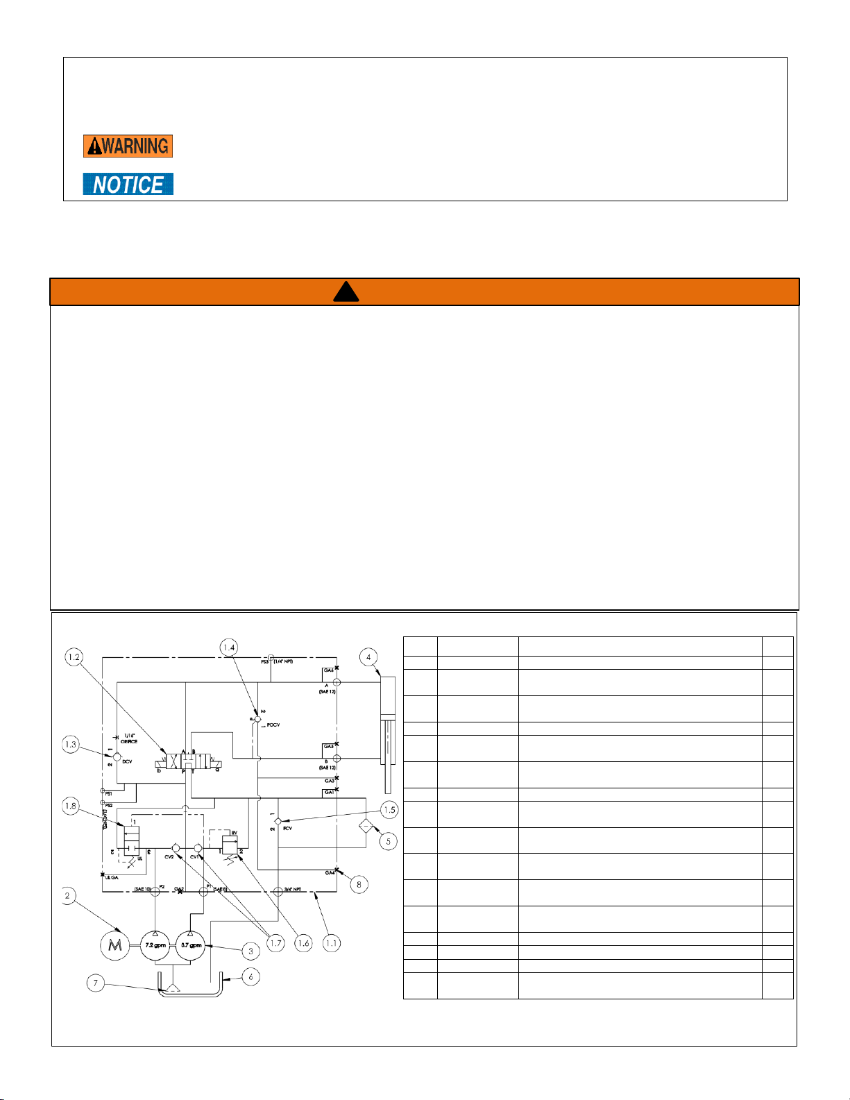
VALVE AND PRESSURE SWITCH ADJUSTMENT PROCEDURE
For locations of valves and switches mentioned to in the following instructions, refer to the figures on page 8.
NOTE: These instructions apply to all HDC-900-IDC units manufactured after June 2011, i.e. units equipped with
manifold 22-127-008 rev C and wired according to electrical circuit diagram 22-124-024 rev D.
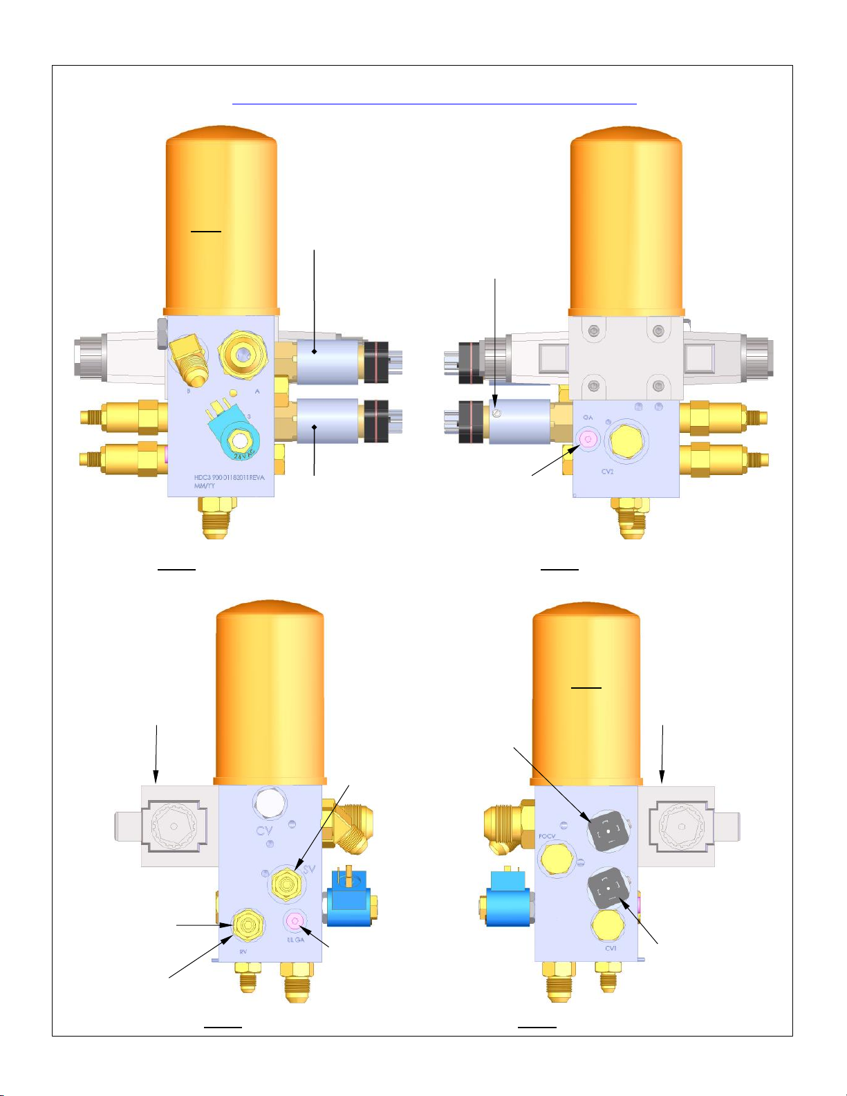
1. Install pressure gauges in ports GA and UL GA. [NOTE: Hose fittings and adapters might be necessary to connect
gauges to these ports.]
a. Remove cap plug from GA port (located under directional valve; see FIG. 6) and install a 3000 psi gauge.
b. Remove cap plug from UL GA port (located under sequence valve and pointing towards motor; see FIG. 7) and
install a 3000 psi gauge.
2. Prepare the pressure switches. See FIGS. 5 & 6.
a. Using a standard screwdriver, loosen the set screws on both of the pressure switches (connected to ports PS1 and
PS2);
b. Turn the knurled knobs of both pressure switches clockwise by hand until they stop.
3. Adjust the relief valve, which is connected to port RV as shown in FIG. 7. Turn the relief valve counterclockwise using
an adjustable wrench on the adjustment hex of the valve.
4. Turn the selector-switch on the control box to “COMPACT”
5. Press the “CYCLE START” button on the control box and hold it until the motor engages. As the motor operates, the
piston rod extends causing the platen to descend towards the bottom of the drum enclosure.
6. Turn the relief-valve clockwise until the pressure at the GA port is 1100 psi.
7. While the motor continues to run and the piston rod is fully extended (platen at the bottom of its cycle), adjust the unload
valve. The valve is connected to port SV. See FIG. 7.
a. Turn the unload valve with an adjustable wrench on the adjustment hex. Typically, adjustment requires turning the
valve clockwise. Turn the valve until the UL GA pressure gauge shows 1000 psi.
b. At this point, the gauge pressure drops approximately to zero, which indicates that the valve shifted. The shift is
also indicated by a change in the sound produced by the motor.
c. The large pump section is now “unloaded”, allowing fluid to return to the tank. The small pump section, however,
remains loaded.
8. Adjust the compacting force:
a. Observe the pressure on the gauge connected to the GA port. Turn the relief-valve clockwise until the GA gauge
shows 1500 psi. The power unit is now operating at 1500 psi pressure.
b. Decrease the setting on PS2—the upper pressure switch shown in FIGS. 5 & 6. Rotate the knurled knob
counterclockwise until it clicks. The click indicates that the directional valve shifted. Consequently, the piston rod
retracts and the platen returns to the raised position. When the platen is fully retracted, the power unit turns off. The
compacting force is now adjusted.
9. Adjust the crushing force:
a. Turn the selector switch on the control box to “CRUSH”;
b. Press the cycle-start button and hold it until the motor engages.
c. While the power unit operates:
i. Increase the relief valve (RV) setting. Turn the valve clockwise until the GA port gauge displays 3000 psi.
ii. As the power unit runs, turn the knurled knob on the lower pressure switch connected to port PS1 (see FIGS.
5& 6) counterclockwise until it “clicks”. The click indicates that the switch is open. Simultaneously, the valve
shifts and the piston retracts (platen rises).
iii. Turn the knob counterclockwise an additional full turn.
iv. Cycle the crusher. As the platen descends, hydraulic pressure will increase until it matches the pressure
switch setting. The goal of this procedure is to adjust the switch setting to 2,500psi. As the crusher cycles,
observe the pressure gauge. Make note of the highest pressure reading achieved during the cycle. If the
highest pressure is not within the range of 2,500psi ± 100psi, adjust the pressure setting: turn the knob
counterclockwise to decrease the setting or clockwise to increase the setting.
d. The crushing force is now adjusted.
10. Return the unit to service:
a. Run the unit through a complete cycle in both modes (COMPACT and CRUSH) to confirm that the machine is
functioning properly.
b. Remove the pressure gauges and reinstall the cap plugs in ports GA and UL GA.
c. Tighten the set screws of the pressure switches PS! And PS2 to fix the positions of the knurled knobs.