Glass Ware 24V Aikido User manual

lass are
GW
AUDIO DESIGN
24V Aikido
Stereo HPA & LSA PCB
USER GUIDE
Introduction
Overview
Schematics
Recommended Configurations
Assembly Instructions
05/30/2008
Rev. A

GlassWare Audio Design
Warning!
Although this PCB was designed for use with a low-
voltage power supply (24V),
caution is still required. For example,
24 volts shorted to ground will make big
sparks; and the large valued electrolytic capacitors must be inserted
correctly
according to their polarity, or they may
burst upon being energized. In addition, this
PCB can also be configured to work with a high-voltage power supply
; thus, a real
shock hazard can also exist. Once ahigh-voltage
power supply is attached, be cautious
at all times.
If you are not an experienced electrical practitioner, before applying any
voltage
supply,
have someone who is experienced review your work. There are too few
tube-loving solder slingers left; we simply cannot afford to lose any more.
A @
Table of Contents
PCB Overview
2
Revision A Features 2
Redundant Solder Pads 2
Dual Outputs 2
Unity-Gain Buffers 2
Aikido Topology Overview
3
Configuring the Tube Linestage
5
Line Stage Amplifier Gain & Zo 6
Internal Shields 6
Cathode Resistor Values 6
Tube Selection 6
Power-Supply Capacitors 7
Heater Issues
7
Series Heater Configuration 7
Series-Parallel Heater Configuration 7
AC Heaters 7
Heater Capacitors 7
Configuring the Solid-State Buffer
8
Headphone Buffers 8
Heatsinks 8
Coupling Capacitors 8
Low-Pass Filter 8
High-Voltage Aikido
10
Headphone Buffers 10
Alternate Heater Arrangement 10
Solid-State Devices 10
High-Voltage Aikido Schematic 11
Typical Part Values 11
Assembly
12
Volume Control 12
Headphone Jack 12
Grounding 12
External Power Supply
13
24-Volt Power Supplies 13
Simple Choke-Based 24V Power Supply 13
Rectifiers 14
6GM8/6N27P/ECC86 Data
15

24V Aikido Stereo Line-Stage/Headphone Amplifier PCB
2
PCB Overview
Thank you for your purchase of the TCJ 24V Aikido stereo PCB, Rev-A. This FR-
4
PCB is extra thick, 0.094 inches (inserting and pulling tubes from their sockets won’t
bend or break this board), double-sided, with plated-through 2oz copper trace
s, and
the boards are lovingly and expensively made in the USA. The boards are five
inches
by ten inches, with eight mounting holes, which also helps
to prevent excessive PCB
bending while inserting and pulling tubes from their sockets. The
PCB holds two
Aikido line-stage amplifiers with two single-
ended output buffers for driving
headphones.T
hus, one board is all that is needed for stereo unbalanced use or one
board for one channel of balanced amplification.
Revision A Features The PCB now holds a second set of pads for the solid-
state
portion of the circuit, which allows high-voltage constant-
current sources and power
MOSFETs to be used instead of the low-voltage regulators. In other words, a high
-
voltage Aikido line-stage/headphone amplifier can be as
sembled. In addition, larger
heatsinks and heater shunting capacitors can be installed.
Redundant Solder Pads This board holds two sets of differently-
spaced solder pads
for each critical resistor, so that radial and axial resistors can easily be used (bulk-
foil
resistors and carbon-
film resistors, for example). In addition, most capacitor locations
find many redundant solder pads, so wildly differing-
sized coupling capacitors can be
placed neatly on the board, without excessively bending their leads.
Dual OutputsThe boards hold two output stages
, one for driving interconnect and
power amplifiers, and a second one for driving low-impedance headphones (32 to 600
-
ohms), with each headphone output holding its own class-A, single-ended, solid-
state,
unity-gain buffer and large coupling capacitor (with bypass option).
Unity-Gain BuffersThis stage makes use of two solid-state, three-
pin voltage
regulators per channel, which greatly simplifies the circuit’s construction
, while
retaining the advantages inherent in the regulators, such as thermal and short-
circuit
current limits. One way to view these regulators is as hot-rodded NPN
power
transistors, with the added feature is being depletion-
mode devices. In other words,
with an LM317 or LT1085 for example, the adjust pin can and must be more
negative
that the output voltage.
One regulator sits atop another, with the top regulator acting
as single-ended buffer/follower. The bottom regulator functions as a constant-
current
source
—
and not a bad one at that.

GlassWare Audio Design 3
The
Aikido
amplifier delivers the sonic goods. It offers low distortion, low output
impedance, a great PSRR figure, and feedback-free amplification. The secret to it
s
superb performance—in spite not using global feedback—
lies in its internal symmetry,
whic
h balances imperfections with imperfections. As a result, the Aikido
circuit works
at least a magnitude better than the equivalent SRPP or grounded-cathode amplifier.
For example, the Aikido circuit produces far less distortion than comparable circuits
by
using the triode’s own nonlinearity against itself. The triode is not as linear as a
resistor,
so ideally, it should not see a linear load, but a corresponding
, complementary, balancing
non-linear load. An analogy is found in someone needing eyeglasses; i
f the eyes were
perfect, then perfectly flat (perfectly linear) lenses would be needed, whereas imperfect
eyes need counterbalancing lenses (non-linear lenses) to see straight. Now,
loading a
triode with the same triode—under the same cathode-to-plate volt
age and idle current
and with the same cathode resistor—
works well to flatten the transfer curve out of the
amplifier.
Aikido Amplifier Topology
B+
Rk
Rk
in
out
R16
R15
Rk
Rk
C13
6GM8
Rg
Rgs
Rgs
Introduction to the Aikido Topology
In the schematic above, the 6GM8 triodes are so specified for example only.
Although
they would never fit on the printed circuit board (PCB), 211 and 845 triodes could be
used to make an Aikido amplifier. In other words, the Aikido
circuit does not rely on
6GM8 triodes or any other specific triodes to work correctly. It’s the topology
, not the
tubes that make the Aikido special.
The secret to the Aikido circuit is that sidesteps power supply noise by
anticipating
and adjusting for that noise so that noise is eliminated from the output. Th
is
improved PSRR advantage is vital, for it greatly unburdens the power-
supply. With no
tweaking or tube selecting, you should easily be able to get a -
30dB PSRR figure (a
conventional grounded-cathode amplifier with the sa
me tubes and current draw yields
only a -6dB PSRR); with some tweaking of resistor R15’s value, -
60dB or more is
possible. Additionally, unless regulated power supplies are used for the plate and
heater, these critical voltages will vary at the whim of the
power company and your
house’s and neighbors’ house’s use, usually throwing the once fixed voltage
relationships askew. Nevertheless, the Aikido amplifier will still function flawlessly, as
it tracks these voltage changes symmetrically.
6GM8
6GM86GM8
1M

24V Aikido Stereo Line-Stage/Headphone Amplifier PCB
4
Remember, tubes are not yardsticks that never change, being more like car tires—
they
wear out. Just as a tire’s weight and diameter decrease over time, so too the tube’s
conductance. Thus afresh 6GM8 is not the same as thesame 6GM
8 after 2,000 hours
of use. But as long as the two triodes age in the same way—
which they are inclined to
do, as they do the same amount of work and share the same materials and
environment—
the Aikido amplifier will always bias up correctly, splitting the B+
voltage between the t
riodes. Moreover, the Aikido amplifier does not make huge
popping sounds
at start up, as the output does not start at the B+ and then swing
down a hundred or so volts when the tube heats up, as it does in a ground-
cathode
amplifier.
This circuit eliminates power-supply noise from the output, by injecting the
a portion
of power-supply noise into the bottom triode of the two-triode-
follower circuit. The
way it works is that the input stage (the first two triodes) define a voltage divider of
50%, so that 50% of the PS noise is presented to the
CF's grid; at the same time
resistors R15 and R16
also define a voltage divider, so the bottom triode's grid also
sees about half
of the PS noise. Since both of these signals are equal in amplitude and
phase, they cancel
each other out, as each triodes sees an identical increase in plate
current (imagine two equally strong men in a tug of war contest).
So, shouldn’t
resistors R15 and R16 share the same value, thereby also splitting the power-
supply
noise at 50%? No. If tr
iode did not present a low plate resistance, then the 50% ratio
would apply. Because of the low rp, the correct relationship between resistors R15 and
R16 is given by the following formula:
R15 = R16[(mu -2)/(mu + 2)]
Furthermore, the Aikido amplifier—like other Aikido techniques I have tried—
seems to
bypass much (but not all)
of the power supply squirrelliness, making the circuit
sound as if it were attached to batteries or a well-
regulated power supply. (This
includes the sonic traces left by imperfect power supply capacitors.)
If an SRPP circuit were used instead as the input stage or if
the output connection
were taken from the cathode follower's cathode, the equilibrium would be broken
,
resulting in a much poorer performance. The same holds true if t
he cathode
follower's cathode resistor is removed. (Besides, this resistor actually makes for a
better sounding cathode follower, as it linearizes the cathode follower at the expense
of a higher output impedance.) In other words, the Aikido topology trades
away the
higher gain and lower output impedance for lower distortion and much-
lower noise.
The formula for the Aikido’s output impedance is the following:
Zo = [rp/(mu +1) + R8] || R14 || [rp + (mu + 1)Rk]
where “||” stands for in “parallel with.” Resistor (R8) should be removed and
R11’s
bypass capacitor (C3)should be used when driving low-impedance headphones, 32
-
ohms for example. When used as a line stage amplifier, however, n
o cathode resistor
bypass capacitors should be used, as these capacitors
are very much in the signal path
and very few do not damage the sound, unless high quality capacitors are used.)

GlassWare Audio Design 5
Configuring the Line Amplifier Portion of the PCB
The Aikido topology makes a
perfect line amplifier, as it offers low distortion, low
output impedance, and excellent power-supply noise rejection—
all without a global
feedback loop. For guidance on part values, look below, which lists several line
-
amplifier design examples. Calculating R15’s value is easy; it’s value equals R1
6
against [(mu -2)/(mu + 2)].
For example, a triode with a mu of 14, such as the 6GM8,
results in R15 = 100k x (14 –2)/(14 + 2) = 75k.
Typical Part Values
() Parentheses denote recommended values
C1 =
C2 =
C3 =
C4 =
C5, C6 =
C7, C8, C9, C10 =
C11 =
C12 =
C13 =
0.1 - 4µF* (Film or PIO) Same
100 - 200pF 100V Same
0.1 - 30µF 100V Same
330µF - 3,900µF 25V 330µF - 2,200µF 50V
0.001 - 0.1µF 160V
2
None
470µF- 4.7kµF* 470µF- 4.7kµF*
1kµF 35V 1kµF 75V
0.1 - 1µF 100V Same
0.1 - 1µF 100V Same
*Voltage rating must equal or exceed B+ voltage
2. Optional, otherwise use shorting jumper
V1, V2, V3, V4 =
All resistors 1/2W or higher
*High-quality resistors essential in this position.
B+ Voltage =
Heater Voltage =
R1,5,6,7,12,14 =
R2,4 =
R3,9,10 =
R8,11 =
R13 =
R17 =
R18 =
R19 =
R16 =
R15 =
6GM8/6N27P/ECC86 12BH7
18V - 26V (24V) 48V
Same as above Same as above
1M Same
100 - 240 (180)* 200 - 300 (249)*
100 - 1k (300)* Same
100 - 240 (180)* 200 - 300 (249)*
10k 10k
10 - 40 (20)* 10 - 40 (20)*
0 - 20 (2)* 0 - 20 (2)*
10k Same
100k Same
75k 78k
R4
R2
in
R8
R11
R3
R9
R1 C5 R5
R6
R12
R7
C6
C1 line out
R10
24V Aikido Schematic (one channel shown)
Reg
Reg
R19
R14 R17
R18
R13
C2 C3
C4
B+
in
adj
out
adj
in
out
J2
R15
R16
to C13
HP
out
V2/V3
V2/V3 V1/V4
V1/V4

24V Aikido Stereo Line-Stage/Headphone Amplifier PCB
6
Line Stage Amplifier Gain & Zo The total gain of a 6GM8-
based Aikido line
amplifier will be close to +15dB, which should work handsomely in most systems. The
output impedance will be less than 600 ohms.
Internal Shields If the triode’s pin 9 attaches to
an internal shield, as it does with the
6CG7,6DJ8, 6GM8/ECC86, and 6H30, then capacitors, C5and C6
can be replaced
with a jumper wire, which will directly
ground the shield. However, using capacitors
will also ground the shield (in AC terms) and allow using triodes whose pin-
9 attaches
to the center tap of its heater, such as the 12BH7.
Cathode Resistor Values
The cathode resistor sets the idle current for the triode: the
larger the value of the resistor, the less current. In general, high-mu triodes r
equire
high-value cathode resistors (1-2K) and low-mu triodes require low-
valued cathode
resistors (100-1k). A 24-
volt B+ voltage means that each triode will have 12 volts (minus
the voltage drop across its cathode resistor) to play with. Looking at the plate curves
on
page 15
reveals that a cathode resistor value between 160 to 200 ohms will set an idle
current of about 2mA. 180ohms is a good starting value.
Now 2mA is not a lot of
current. Nevertheless, as long as short, low-capacitance interconnects are
driven, the
bandwidth should not suffer too greatly.
(Driving capacitance at fast slew rates requires current. The faster you want to charge a
capacitance, the more current you will need. A low-
output impedance is nice, but
without the ability to deliver current into a capacitance-
laden load, it is not enough. In
other words, although atube-based line amplifier is unlikely to be voltage limited
, it
may be current limited.)
Tube Selection Unlike 99.9% of tube circuits, the Aikido amplifier defines a ne
w
topology without fixed part choices, not an old topology with specified part choices. In
other words, an Aikido amplifier can be built in a nearly infinite number of ways.
A low-voltage Aikido, on the other hand, offers greatly reduced choices. The per
fect
choice is the 6GM8/ECC86/6N27P, a small 9-pin, dual triode that
designed to be used
as an RF amplifier and as a self-
oscillator mixer in a car radio, back when car radios
held tubes. Unlike most triodes, it works quite well with only 12 volts on its plate
(a
maximum plate voltage of only 30V)
. Additionally, like the 6DJ8/6922 this little triode
stows a grid frame, making it doubly rare. Fortunately, it shares the same pinout as the
6DJ8/6922, so in a pinch, the 6DJ8 can be used instead, for example the
6H30 or
12BH7 or ECC99.
For the advanced practitioner, a high-
voltage Aikido line stage amplifier can be
assembled on the PCB, which allows other dual triodes to be used.
The only
stipulations are that the two triodes within the envelope be identical an
d that the tube
conforms to the 9A or 9AJ base pin-out
and that input and output tube share the same
heater current. See page 10.

GlassWare Audio Design 7
Power-Supply Capacitors
The PCB holds two positions for power supply capacitors,
C11 ad C12. Capacitor C11 should be rated for more than the power supply voltage
and should be at east 1kµF in capacity. Obviously, an electrolytic will be needed. This
large capacitor should be bypassed with a high-
quality plastic film or PIO capacitor.
Because the B+ voltage is so low, low-
voltage capacitors can be used that would not
work in most tube projects.
Two sets of pads are provided, which allows two types of powe
r supply capacitors to be
used: 10mm-spacing, snap-
mount, electrolytics, such as the Nichicon KG series; and
the 0.3inch-
spacing radial electrolytics, such as from the Panasonic FM series. When
using a snap-mount capacitor, rotate the capacitor so that its
positive terminal points
to the right side of the PCB; when using a through-
hole radial capacitor, align the
positive terminal to the towards capacitor C12. A volt
age rating of 35V is adequate for
a 24V Aikido.
Of course, if a high-voltage Aikido is planned, a high-
voltage power supply capacitor
will be needed for capacitors C11, C12, and C13.
Heater Issues
Series Heater Configuration Assuming that a DC 18Vto 26V
power supply will be
used for both the B+ voltage and the heater power supply, which will
work well with
the 6GM8/ECC86/6N27P dual triodes, use jumper J1. Different tubes can be used
,
however, as long as heaters see the correct voltage. For example, four 12BH
7s can be
used with a 48V power supply for both the B+ voltage and the heater string.
AT ALL
TIMES, ALL THE HEATERS MUST SHARE THE SAME CURRENT DRAW.
For
example, 6CG7 and 6DJ8 tube cannot coexist on the board, as the heaters
differ
incurrent draw
; a 12AT7 and 12AU7, in contrast, can be used, as both draw the same
150mA of heater current.
Series-Parallel Heater Configuration
If a separate heater power supply and B+ power
supply are used, the heaters can be placed in a series-
parallel configuration by using
jumpers, J3 and J4. Once again,
ALL THE HEATERS MUST SHARE THE SAME
CURRENT DRAW.
A
C Heaters An AC heater power supply
can be used, if the heater shunting capacitors
C7, C8, C9, C10 are left off the board, or are replaced by 0.01µF ceramic capacitors
,
and if the heater power supply is independent of the B+ power supply.
Not
recommended in the least.
Heater Capacitors.IMPORTANT! The
heaters are all placed in series, so each heater
sees one fourth of the B+ voltage. So, we might assume that each heater bypass
capacitor will only see the same one fourth of the B+ voltage; and they do, wh
en all the
heaters are conducting. But what happens when one tube is removed from its socket or
when one heater element becomes open? The answer is that the remaining three
heaters become effectively dead shorts and the heater bypass capacitor that is now
missing its heater element now see the full B+ voltage! In other words, each heater
capacitor must be rated for the full heater-power-supply voltage to be safe.

24V Aikido Stereo Line-Stage/Headphone Amplifier PCB
8
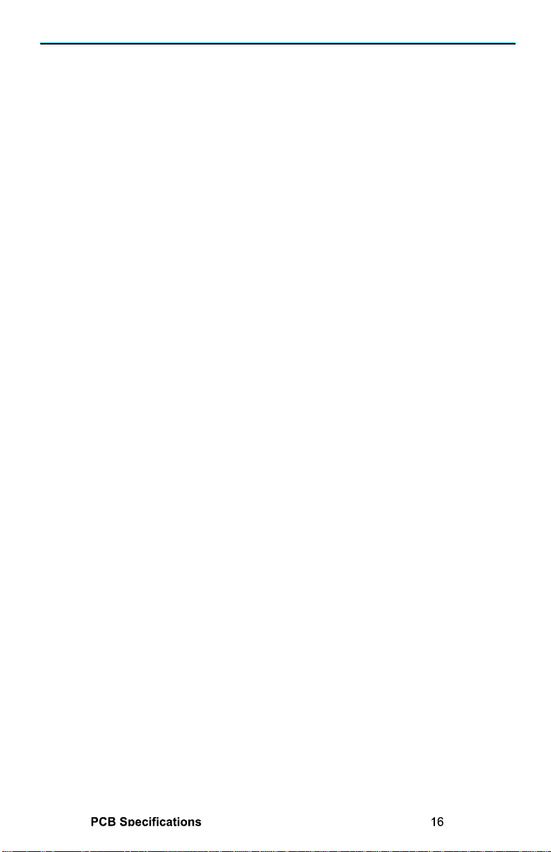
Configuring the Headphone Driver Portion of the PCB
The standard Aikido is a thoroughly single-
ended affair, nothing pulls while
something else pushes. Unfortunately, wonderful as single-
ended mode is sonically, it
cannot provide the larger voltage and current swings that a push-
pull output stage can.
Single-ended stages can only deliver up to the idle current into a load, whereas class-
A
push-pull stages can deliver up to twice the idle current; and class-
AB output stages
can deliver many times the idle cu
rrent. For a line stage, such big voltage and current
swings are seldom required; headphones, on the other hand, do demand a lot more
power; really, a 32-
ohm load is brutally low impedance for any tube to drive.
Unfortunately, a heavy idle current is needed to ensure large voltage swings into low-
impedance loads
, something that the little 6GM8 (or any other tube) cannot do with
just 12V on the plate.
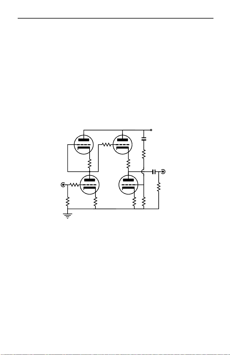
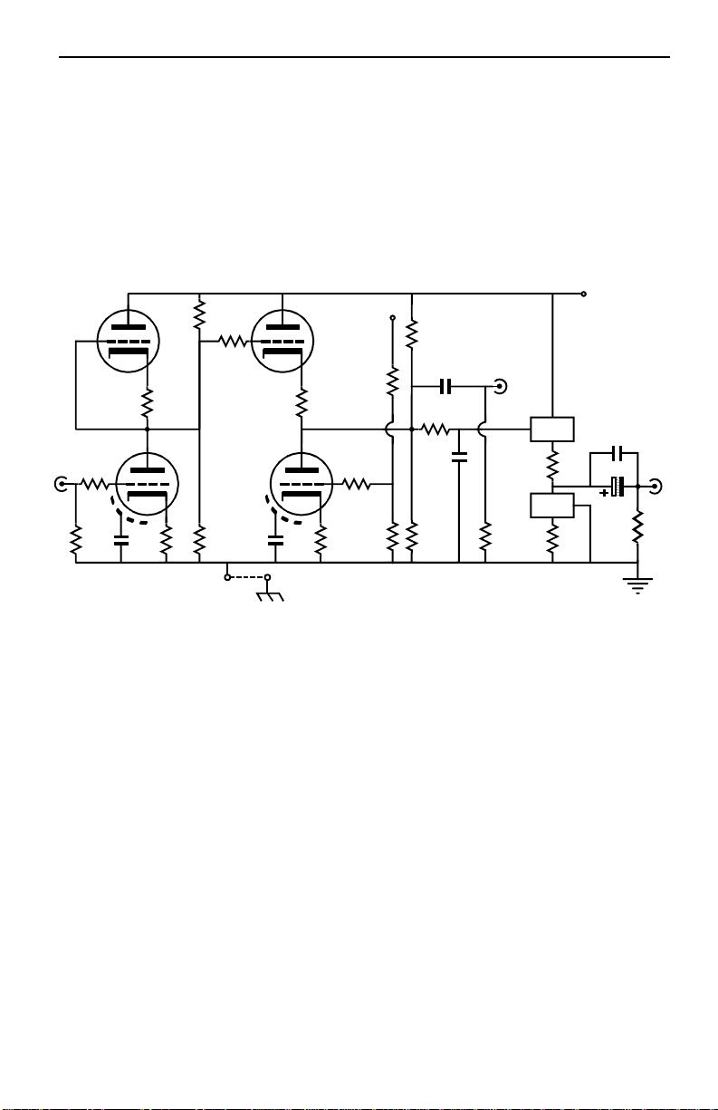
Headphone Buffers The solid-state, class-A, unity-
gain buffer receives its signal
directly from the Aikido’s output. Then, it delivers the needed high-
current swings
into the headphones. Two three-
pin, adjustable voltage regulators are used per
channel, one as a unity-gain follower and one as a constant-
current source. LM317,
LM350, LT1085 adjustable regulators can be used.
Resistor R17 sets the idle current through output stage and 20 to 40 ohms is a good
value.
The formula for setting the desired idle current is simple enough: Iq =
1.25/R17. The heatsinks will prove to be the greatest limiting factor in how
high an
idle current can be used, as the PCB-mount TO-
220 heatsinks can dissipate only up to
5W because of their small size. In other words, although the solid-
state device may be
rated at 40W, limit it dissipation to the rated dissipation of the heatsink
used.
Resistor R18 is optional and
serves to buffer the output device from the load and
helps linearize the transfer function, but at the cost of slightly greater output
impedance; 1 to 10 ohms is a useful range of values.
Heatsinks Heatsinks can be soldered to the PCB; the hole spacing is 1 inch
; a good
choice is the Aavid Thermalloy (Mouser Part # 529902B02500G), which is 25.4
mm
deep, 42mm wide, and 50.8mm tall. The solid-
state devices should be isolated from
the heatsinks and either thermal grease or gasket material must be used.
Be sure that
the heatsinks do not touch resistor R18’s pads or the bottommost mounting holes.
Coupling CapacitorsA headphone
coupling capacitor of at least 33µF is required
when driving 300-ohm headphones; 330µF for 32-ohm headphones
; but many will opt
for much larger capacitors, say 2kµF.
So why use a much larger capacitor? A larger
capacitor value extends the low frequency cutoff and reduces the phase shift in the
audio band. Think quality over quantity. Use only film c
apacitors if you can; and if
an electrolytic coupling capacitor must be used, use a high-
quality electrolytic, with
low ESL and good high-
frequency performance, such as is offered by the Panasonic
FM series of capacitors. Be sure to use a high-quality, relatively small-
valued bypass
capacitor in C3’s position, say from 0.1µF to 10µF capacitors.
Low-Pass Filter The PCB also offers the provision for a low-
pass filter going into the
solid-state output buffer for headphones. This filter limits the high-frequ
ency
bandwidth, as a safety precaution. Resistors R19
can be 10k in resistance and
capacitors C2 can be any
value between 100pF to 300pF.

GlassWare Audio Design 9
V1
V2
V3
V4
C8
C7
C9
C10
H+
H-
J1
Heater Schematic
J3
J4
CAUTION
Heater bypass capacitors must be rated for the full
B+ voltage, when wired in series and share the
B+ connection, say a 25V capacitor with B+ of 24V.
C13
C12 C11
to R15
B+
Power Supply Schematic
Common to both channels
1 2 3
T
TO-220
Three-Pin Voltage Regulator (LM317, LT1085)
1 = Adjust, 2 = Vout, 3 = Vin, T = Vout
HV Current Regulator (IXCP 10M45S)
1 = Gate, 2 = Anode, 3 = Cathode, T = Anode
Typical HV MOSFET (FQP5N40)
1 = Gate, 2 = Drain, 3 = Source, T = Drain
TO-220 Pinout
HV Current Regulator (IXCP 10M45S) Idle current vs cathode resistor value

24V Aikido Stereo Line-Stage/Headphone Amplifier PCB
10
Since the heater string and the B+ do not share a single
power supply, a voltage
relationship must be established between the heater power supply and the B+ power
supply. Because one triode stands atop another, the heater-to-
cathode voltage
experienced between triodes differs
. The safest path is to reference the heater power
supply to a voltage equal to one fourth the B+ voltage; for example, 2
5V, when using a
1
00V power supply. The ¼ B+ voltage ensures that both top and bottom triodes see
the same magnitude of heater-to-
cathode voltage. The easiest way to set this voltage
relationship up is the above circuit.
Solid-State Devices The IXCY 10M45S constant-regulator is a high-
voltage device
that works well as the output stage’s active load. The output device
can be either an
additional IXCY 10M45S or any high-voltage, low-wattage, N-channel MOSFET in a
TO-220 package that conforms to the gate-drain-source pinout configuration.
These
two solid-state device mount on the backside of the heatsinks. Because of the high-
voltages involved, it is critical that theses solid-
state devices are isolated from the
heatsinks and extra care must be given to ensuring that the heatsinks do not touch
resistor R18’s pads or the bottommost mounting holes.
High-Voltage Aikido line-stage/Headphone Amplifier
The PCB allows configuring a high-voltage Aikido as well as the low-
voltage version.
Why? The sad fact is that the 6GM8 is being used up and it is not a renewable
resource. On the other hand, 6CG7, 6DJ8, and 12AU7 continue to be made.
Headphone Buffers In the high-voltage version, the solid-state, unity-gain buffer
still
receives its input signal directly from the tube’s output. The two three-
pin, adjustable
voltage regulators, however, are replaced with a high-
voltage, power MOSFET as the
output device, and a high-voltage current regulator as the active load.
Resistor R17
still sets the idle current through output stage and
its value can be gleaned from the
accompanying graph on the top of page 9. Once again, t
he heatsinks will prove to be
the greatest limiting factor in how high an idle current can be used, as the PCB-
mount
TO-220 heatsinks can dissipate only up to 5W.
Alternate Heater Arrangement
The heater string must receive its own power supply
connection and should be wired heaters placed in series-
parallel so that 12.6Vdc power
supply can be used with 6.3V tubes. In this setup, jumper J1 is not used; instead,
jumpers, J3 and J4 are used. For example,
with a 12V heater power supply, a B+
voltage of 170V could be used with four 6922
or 6CG7 or 6H30 tubes; remember no
mixing and matching with these tubes, as each holds a different heater current draw.
V1
V2
V3
V4
C8
C7
C9
C10
H+
H-
J1
Heater Schematic
J3
J4
DC
Heater
PS
300k
2W
100k
1/2W
B+
B+
4
0.1µF
250V
Heaters
12.6Vdc
or
25.2Vdc
Heater Bias Schematic

GlassWare Audio Design 11
IXCP
10M45S
K
G
A
input
output
R4
R2
R8
R11
R3
R9
R1 R5
R6
R12
R7
R10
R19
R17
R18
R13
R15
R16
C2
C13
V2 or V3 V1 or V4
B+
Typical Part Values
() Parentheses denote recommended values
C1 =
C2 =
C3 =
C4 =
C5, C6 =
C7, C8, C9, C10 =
C11 =
C12 =
C13 =
0.1 - 4µF* (Film or PIO) Same Same
0 - 1,000pF 250V Same Same
0.1 - 30µF 250V Same Same
470µF/160V
2
470µF/200V
2
470µF/100V
2
0.001 - 0.1µF 160V
2
Same Same
2kµF/25V 2kµF/16V 2kµF/16V
33µF/200V* 33µF/250V* 33µF/160V*
0.22 - 1µF 250V
2
0.22 - 1µF 250V
2
0.22 - 1µF 160V
2
0.1 - 1µF 250V
2
Same Same
*Voltage rating must equal or exceed B+ voltage
2. Optional, otherwise use shorting jumper
V1, V2, V3, V4 =
All resistors 1/2W or higher
*High-quality resistors essential in this position.
1. Requires separate heater and B+ power supplies.
B+ Voltage =
Heater Voltage =
R1,5,6,7,12,14 =
R2,4 =
R3,9,10 =
R8,11 =
R13 =
R17 =
R18 =
R19 =
R16 =
R15 =
12AU7 6CG7 6DJ8/6922
100-200V (150V) 200V - 300V (200V)
1
100V - 200V (100V)
24V - 25V
1
12V - 12.6V
1
12V - 12.6V
1
1M same Same
200 - 470 (270)* 300 - 1k (400)* 70 - 240 (180)*
100 - 1k (300)* Same Same
200 - 470 (240)* 300 - 470 (400)* 70 - 240 (180)*
10K same same
40 - 60 (47)* same same
0 - 20 (2)* same same
10k Same Same
100k Same Same
75k 83.2k 87.5k
High-Voltage Aikido Schematic
HV MOSFET
G
D
S
C4
C3
HV MOSFET
IXCP
10M45S

24V Aikido Stereo Line-Stage/Headphone Amplifier PCB
12
Assembly
Before soldering, be sure to clean both sides of the PCB with 90% isopropyl alcohol,
wiping away all fingerprints. First, solder the shortest parts (usually the resistors) in
place, then the next tallest parts, and then the next tallest... Make su
re that both the
solder and the part leads are shiny and not dull gray. Steel wool can restore luster and
sheen by rubbing off oxidation.
Solder in place the lowest-
profile devices first, which usually are the resistors; then the
next tallest; ending with the heatsinks for the solid-state devices.
As the PCB is doubled sided, parts can be soldered in place from either side. In fact,
many of the parts can be positioned on the bottom side of the PCB; the exceptions
being the tubes and the three-pin solid-s
tate devices, as these parts must always be
positioned on the top of the board.
Important:B
e sure to observe the electrolytic capacitors' polarity and glue or
double-sided tape or tie-wrap heavy coupling capacitors to the PCB.
Volume Control
An audio-
taper potentiometer or stepped attenuator can be placed
in front of the Aikido amplifier. Of course, a volume control may not be needed, if
the signal source already provides the means of volume adjustment, such as an MP3
player or a line stage amplifier.
Headphone Jack
Large electrolytic coupling capacitors suffer from leakage current
across the capacitor, which against the terminating resistance defines a small DC
offset voltage. The higher the resistance, the greater the voltage. This offset voltage
can
create an annoying popping sound when headphones are plugged into the headphone
jack. One workaround is to limit the size of the electrolytic to no more than 330µF
and to use a 470-
ohm terminating resistor (R13), which will limit the DC offset. A
bett
er approach might be to use a headphone jack that holds two switched contacts
that open when the headphone prong is inserted, as the two switched contacts can
attach to 10-
ohm resistors, which in turn terminate into ground. Such an arrangement
will force t
he DC offset down to vanishingly low amounts and will not burden the
headphone amplifier when in actual use.
Grounding
Jumper J2 connects the PCB’s ground to the chassis through the top
centermost mounting hole. If you wish to float the chassis or capac
itor couple the
chassis to ground, then either leave jumper J2out or replace it with a small-
valued
capacitor (0.01 to 0.1µF). Warning: if rubber O-
rings are used with PCB standoffs,
then the ground connection to the chassis is not likely to be made.
Let me know what you think
If you would like to see some new audio PCB or kit or recommend a change to an
existing product or if you need help figuring out cathode re
sistor values, drop me a
line by e-mail to the address above (begin the subject line with ei
ther “Aikido” or
“tube”).

External Power Supply
The genius of the Aikido circuit is found in both its low distortion and great PSRR
figure. Nonetheless, a good power supply helps (there is a practical limit to how
large a power-supply noise signal can be nulled). I recommend you us
e at least a
solid, choke-filtered tube or fast-
diode rectified power supply. If you insist on going
the cheap route, try the circuit below, as it yields a lot of performance for little
money. FRED rectifiers are expensive, but make an excellent upgrade to
the lowly
1N400X rectifier.
The power supply is external to the Aikido PCB and can be mounted in, or outside,
the chassis that houses the PCB. The optimal power supply voltage depends on the
tubes used. Four 6GM8s (6N27P/ECC86) can be used with a low 24V power supply
,
either a switch-mode or a linear power supply.
24
-Volt Power Supplies After dealing with 400-
volt power supplies, it is a joyful
relief to work with non-
lethal voltages. However, we must address a few important
issues. For example, althoug
h we do not need much voltage, the heaters add a heavy
current burden on the power supply. The heater string requires 330mA and the four
6GM8 tubes require a total of 8mA, for a grand total of 338mA or (rounding up)
350mA. So, 0.35A against 24V equals 8.4W of dissipation.
The 24V Aikido is a perfect candidate for a wall-
wart power supply. Both linear and
switch-mode wall-
warts are available with a 24V output voltage and both cost less
than $30 USD. A medical-grade switch-mode power supply cost about $45 an
d it
will be both safer and more quiet. On the other hand, a simple non-
regulated power
supply can be built from an 18V-
20Vac power transformer, a diode bridge, and a few
capacitors. It just might sound good as well.
All Diodes = 1N5402 or better
All Resistors = 1 ohm 1/2W - 2W
.01µF
100V
.01µF
100V
.01µF
100V
.01µF
100V
100mA
Low-DCR
1kµF
35V to 50V 1kµF
35V to 50V .1µF to 1µF
100V
24VA
24Vac/1A
Secondary
+24Vdc
However, I would prefer to be a bit more nervous. For although the Aikido boasts an
excellent PSSR figure, I don’t want to tax it any more than necessary. Even if the power
supply isn’t regulated, a few small tricks will deliver big sonic gains. For exampl
e,
chokes perform wonders in stripping away power supply blemishes.
Simple Choke-Based 24V Power Supply

24V Aikido Stereo Line-Stage/Headphone Amplifier PCB
14
470µF
35V
AC
124
2.4K
1N4002
REG
Adj
InOut
Heater/B+
D2 C2D1
C1
D4 C4D3
C3
Regulator = LM317 or LM350 or LT1085
C1, C2, C3, C4 = 0.001 to 0.1µF, 100V
I have found that just about any choke, of any inductance or DCR, is better than not
using a choke in a power supply, even if that power supply terminates in a voltage
regulator. One inductor and one extra capacitor added to the simple power supply
will ma
ke a big difference in performance. In fact, a bigger difference than might be
expect in normal tube gear. Why? Inductors work best working into a dead short. As
the terminating resistance increases, the inductor loses effectiveness, just the opposite
of acapacitor. Fortunately, for this inductor-
based power supply, the heater string
represents a 76-
ohm resistive load, whereas the tubes alone represent a 3k load.
Therefore, what started out as a liability (having to power the heater string) becomes
an advantage to the inductor-filled power supply.
Because the current draw is so high, the inductor’s DCR becomes an import circuit
element, as the voltage drop across the inductor will steal a much larger percentage of
the available B+ voltage than it would in
the normal tube line amplifier, which might
only draw 20mA. In other words, a low DCR is critical. I would place a DCR limit of
10 ohms, as a 10-
ohm DCR will displace 3.4V, which will demand a 22Vac
transformer winding to yield 24V for the B+.
Rectifiers I recommend ultra-
fast rectifiers, such as the popular HEXFREDs or the
unpopular Schottky diodes. (Developed by International Rectifier, in the 1970s,
“FRED” stands for Fast Recovery Epitaxial Diode, thus the trade name “HEXFRED.”
Today, manufacturers in
clude Harris, International Rectifier, IXYS and others. Tube
folk do not know about Schottky diodes because, until recently, it was not possible to
buy a high-
voltage Schottky diode. But these fast rectifiers also make for cleaner power
supplies.) IXYS DSEI8-
06A rectifiers cost less than a dollar, so no one will have to take
out a loan. The worse choice, other than a WE274B
rectifier (too much current draw),
is the cheap and ubiquitous 1N4001. This rectifier works well in many non-
audio
applications, but it spurs too much switching-
induced noise into an audio power
supply. Still I know that many readers will opt for them, as they already own several
dozen. If you insist on using them, then build the circuit above
. Paradoxically, the
added capacitors actually slow the diodes, while the 1-
ohm resistors help soften the
transitions between conduction and non-
conduction. And the choke filters away the
ripple. A low-voltage, linear-regulated
power supply is easy to build, as shown
below. Care must be taken no to ex
ceed the regulator’s maximum input
voltage and adequate heat-sinking is required.
25V
1N4002
470µF
35V
1kµF
50V

6GM8/6N27P/ECC86 Specifications
Heater Voltage 6.3V
Heater Current 330mA
Maximum Plate Voltage 30V
Maximum Plate Dissipation 0.6W
Maximum Cathode Current 20mA
Maximum Grid Resistor 1M
Maximum Cathode-to-heater Voltage 30V
Maximum Cathode-to-heater Resistance 20k
Amplification Factor 14
Transconductance 2.4mA/V
Plate Resistance 5800 Ohms

16
R20
Top Side PCB Mechanical Layout
OVERALL PC BOARD DIMENSIONS: 4.00" x 10.0"8 MOUNTING HOLE LOCATIONS
2.00" 2.75" 2.75" 2.00" .25"
.125R, 4 PLCS
4 VACUUM TUBE LOCATIONS
0.85"
1.60"1.60" 2.30"2.30"
5"

www.glass-ware.com
www.tubecad.com
Copyright © 2008
All Rights Reserved
lass are
GW
AUDIO DESIGN
Table of contents
Other Glass Ware Amplifier manuals
Popular Amplifier manuals by other brands

REIMESCH KOMMUNIKATIONSSYSTEME GMBH
REIMESCH KOMMUNIKATIONSSYSTEME GMBH ALPIN 100 MK III user manual

Drawmer
Drawmer 1962 Operator's manual

Bo EDIN AB
Bo EDIN AB UniVox DLS-50 user guide

VocoPro
VocoPro DA-3600Pro2 owner's manual

NXP Semiconductors
NXP Semiconductors BGA2714 Brochure & specs

Chord
Chord CA30 user manual