Camille Bauer SIRAX TV 808-61 User manual

1
Betriebsanleitung
Trennverstärker SIRAX TV 808-61
Mode d’emploi
Amplificateur-Séparateur SIRAX TV 808-61
Operating Instructions
Isolating amplifier SIRAX TV 808-61
TV 808-61 Bd-f-e 125 171-01 06.05
Camille Bauer AG
Aargauerstrasse 7
CH-5610 Wohlen/Switzerland
Telefon +41 56 618 21 11
Telefax +41 56 618 35 35
e-mail: info@camillebauer.com
http://www.camillebauer.com

2

3
Betriebsanleitung
Trennverstärker SIRAX TV 808-61 ........................................ Seite 4
Mode d’emploi
Amplificateur-Séparateur SIRAX TV 808-61 ......................... Page 9
Operating Instructions
Isolating amplifier SIRAX TV 808-61 .................................. Page 14
Sicherheitshinweise, die unbedingt beachtet
werden müssen, sind in dieser Betriebsanlei-
tung mit folgenden Symbolen markiert:
Les conseils de sécurité qui doivent impé-
rativement être observés sont marqués des
symboles ci-contre dans le présent mode
d’emploi:
The following symbols in the Operating In-
structions indicate safety precautions which
must be strictly observed:
Geräte dürfen nur fachgerecht entsorgt werden!
Les appareils ne peuvent être éliminés que de
façon appropriée!
The instruments must only be disposed of in
the correct way!

4
Betriebsanleitung
Trennverstärker SIRAX TV 808-61
Inhaltsverzeichnis
1. Erst lesen, dann... ........................................................ 4
2. Lieferumfang ................................................................4
3. Bestellangaben .............................................................4
4. Kurzbeschreibung ........................................................5
5. Übersicht der Funktionselemente ................................5
6. Technische Daten .........................................................5
7. Mechanische Codierung des Steck-Moduls ................6
8. Elektrische Anschlüsse .................................................6
9. Gerät öffnen und schliessen .........................................7
10. Trennverstärker konfigurieren .......................................7
11. Montage .......................................................................8
12. Inbetriebnahme ............................................................8
13. Wartung ........................................................................8
14. Demontage-Hinweis .....................................................8
15. Mass-Skizze .................................................................8
16. Konformitätserklärungen ............................................19
1. Erst lesen, dann …
Der einwandfreie und gefahrlose Betrieb
setzt voraus, dass die Betriebsanleitung
gelesen und die in den Abschnitten
7. Mechanische Codierung des
Steck-Moduls
8. Elektrische Anschlüsse
11. Montage
12. Inbetriebnahme
enthaltenen Sicherheitshinweise beachtet werden.
Der Umgang mit diesem Gerät sollte nur durch entspre-
chend geschultes Personal erfolgen, das das Gerät kennt
und berechtigt ist, Arbeiten in regeltechnischen Anlagen
auszuführen.
Das Gerät darf nur zum Konfigurieren, wie in Abschnitt
«10. Trennverstärker konfigurieren» beschrieben, geöffnet
werden!
Bei weitergehenden Eingriffen in das Gerät erlischt der
Garantieanspruch!
2. Lieferumfang (Bild 1)
(1)
(3)
GOSSEN
METRAWATT
CAMILLE BAUER
Konfiguration / Configuration SIRAX TV 808
Kanal 1
Channel 1
Kanal 2
Channel 2
Eingang
Input
Ausgang
Output
Anlage/Mess-Stelle
Plant/Measuring point
GOSSEN
METRAWATT
CAM ILLE BAUER
Konfiguration / Configuration SIRAX TV 808
Kanal 1
Channel 1
Kanal 2
Channel 2
Eingang
Input
Ausgang
Output
Anlage/Mess-Stelle
Plant/Measuring point
GOSSEN
METRAWATT
CAMILLE BAUER
Anlage/Mess-Stelle
Messeingang
Fühlertyp
Temperatur-Messbereich
Messausgang
Anfahr-Festwert währ. 5 s
Einstellzeit
Bruchsignalisierung
Netzbrumm-Unterdrückung
Grenzwertfunktion
Konfiguration / Configuration SIRAX V 644
Plant/Measuring point
Measuring input
Sensor type
Temperature range
Measuring output
Start up value during 5 s
Setting time
Open-circ. superv.
Mains ripple suppression
Output contact
inactive
50 Hz
inactive
active
60 Hz
active
(2)
(5) (4)
Aargauerstrasse 7
CH-5610 Wohlen/Switzerland
Telefon +41 56618 21 11
Telefax +41 56618 24 58
Telex 827 901 cbm ch
TV 808-61 B d-f-e 125 171 09.97
Betriebsanleitung
Trennverstärker SIRAX TV 808-61
Mode d’emploi
Amplificateur-Séparateur SIRAX TV 808-61
Operating Instructions
Isolating amplifier SIRAX TV 808-61
Trennverstärker (1)
3 Infokarten (2) (zum Eintragen der konfigurierten Daten)
1 Codierkamm (3)
(zum Codieren des Geräteträgers SIRAX BP 902)
1 Ex-Bescheinigung (4) (nur für Geräte in Ex-Ausführung)
1 Betriebsanleitung (5), dreisprachig: Deutsch,
Französisch, Englisch
3. Bestellangaben
MERKMAL KENNUNG
1. Bauform
Gehäuse B17 808 - 6
2. Anzahl Kanäle
1 Kanal 1
3. Ausführung / Hilfsenergie
Standard, 24 … 60 V DC/AC 1
Standard, 85 … 230 V DC/AC 2
[EEx ia] IIC, 24 … 60 V DC/AC
Eingang eigensicher 3
[EEx ia] IIC, 85 … 110 V DC/230 V AC
Eingang eigensicher 4
4. Funktion
1 Eingang, 1 galvanisch getrennter
Ausgang 1
5. Eingangssignal
Eingang [V]
gemäss Typenschild 9
Eingang [mA]
gemäss Typenschild Z
6. Ausgangssignal
Ausgang [V]
gemäss Typenschild 9
Ausgang [mA]
gemäss Typenschild Z

5
4. Kurzbeschreibung
Der aktive Trennverstärker SIRAX TV 808 hat die Aufgabe,
Eingangssignale von Ausgangssignalen galvanisch zu tren-
nen, sie zu verstärken und/oder in einen anderen Pegel oder in
eine andere Signalart (Strom oder Spannung) umzusetzen.
5. Übersicht der Funktionselemente
Bild 2 zeigt die wichtigsten Teile, die im Zusammenhang mit
den elektrischen Anschlüssen und anderen in der Betriebsan-
leitung beschriebenen Vorgängen behandelt werden.
Bild 2
(2) Infokarte
(6) Typenschild
(7) Schnellbefestigung
Rote Leuchtdiode ohne Funktion
ON Grüne Leuchtdiode für Betriebszustand
6. Technische Daten
Messeingang
Gleichstrom: Standardbereiche
0…20 mA, 4…20 mA, ± 20 mA
Grenzwerte 0…0,1 bis 0…50 mA
auch live-zero,
Anfangswert > 0 bis
≤ 50% Endwert
– 0,1…0…+ 0,1 bis
– 50…0…+ 50 mA
auch bipolar asymmetrisch
Ri = 15 Ω
Gleichspannung: Standardbereiche
0…10 V, 2…10 V, ± 10 V
Grenzwerte
0…0,06 bis 0…40, Ex max. 30 V
auch live-zero,
Anfangswert > 0 bis
≤ 50% Endwert
– 0,06…0…+ 0,06 bis
– 40…0…+ 40 V,
Ex max. – 30…0…+ 30 V
Ri = 100 kΩ
(7)
(6)
ON
(2)
Span
Zero
ohne
Funktion
Überlastbarkeit: Gleichstrom
dauernd 2-fach
Gleichspannung
dauernd 2-fach
Messausgang
Gleichstrom: Standardbereiche
0…20 mA, 4…20 mA, ± 20 mA
Grenzwerte
0…1 bis 0…20 mA
0,2…1 bis 4…20 mA
– 1…0…+ 1 bis –20…0…+ 20 mA
Bürdenspannung: 12 V
Rext max. [kΩ] = 12 V
IAN [mA]
IAN = Ausgangsstromendwert
Gleichspannung: Standardbereiche
0…10 V, 2…10 V, ± 10 V
Grenzwerte
0…1 bis 0…10 V
0,2…1 bis 2…10 V
– 1…0…+ 1 bis – 10…0…+ 10 V
Bürde: ≥ 2 kΩ
Strombegrenzung bei
Rext max.: Ca. 1,1 × IAN bei Stromausgang
Spannungsbegrenzung
bei Rext = ∞: Ca. 13 V
Restwelligkeit des
Ausgangsstromes: < 0,5% p.p.
Einstellzeit: < 50 ms
Hilfsenergie H
Allstrom-Netzteil (DC und 45...400 Hz)
Tabelle 1: Nennspannungen und Toleranz-Angaben
Nennspannung
UN
Toleranz-Angabe Geräte-Ausführung
24... 60 V
DC / AC DC – 15...+ 33%
AC ± 15%
Standard
(Nicht-Ex)
85...230 V 1
DC / AC
24... 60 V
DC / AC
DC – 15...+ 33%
AC ± 15% In
Zündschutzart
Eigensicherheit
[EEx ia] IIC
85...230 V
AC ± 10%
85...110 V
DC –15...+ 10%
1 Bei DC-Hilfsenergie > 125 V sollte im Hilfsenergiekreis eine externe
Sicherung mit einem Abschaltvermögen von ≤ 20 A DC vorgesehen
werden.
Leistungsaufnahme: ≤ 1,2 W bzw. ≤ 3 VA
Genauigkeitsangaben (Analog DIN/IEC 770)
Grundgenauigkeit: Fehlergrenze ≤ ± 0,2%
Linearitätsfehler und Reproduzier-
barkeit eingeschlossen
Umgebungsbedingungen
Inbetriebnahme: – 10 bis + 40 °C
Betriebstemperatur: – 25 bis + 40 °C,
Ex – 20 bis + 40 °C
Lagerungstemperatur: – 40 bis + 70 °C
Aussenwiderstand:

6
8. Elektrische Anschlüsse
Der Trennverstärker SIRAX TV 808 wird auf einen Geräte-
träger BP 902 aufgesteckt. Die elektrische Verbindung zwi-
schen Trennverstärker und Geräteträger erfolgt über einen
96-poligen Steckverbinder (Bauform C, DIN 41612). Die
Steckerbelegung geht aus Bild 5 hervor.
Die Anschlussbelegung des Geräteträgers entnehmen Sie
bitte unserer Betriebsanleitung für den Geräteträger.
Unbedingt sicher stellen, dass die Leitungen
beim Anschliessen spannungsfrei sind!
Möglicherweise drohende Gefahr,
230 V Netzspannung als Hilfsenergie!
Bei Geräten in der Zündschutzart «Eigen-
sicherheit» [EEx ia] IIC sind zusätzlich die
Angaben der Baumusterprüfbescheinigung
sowie die nationalen Vorschriften für die
Errichtung von elektrischen Anlagen in
explosionsgefährdeten Bereichen zu be-
rücksichtigen.
Ferner ist zu beachten, …
… dass die Daten, die zur Lösung der Messaufgabe
erforderlich sind, mit denen auf dem Typenschild
des SIRAX TV 808 übereinstimmen ( Messein-
gang, Messausgang, Hilfsenergie!).
… dass der Gesamtwiderstand in der Messaus-
gangsleitung (in Serie geschaltete Empfangsgeräte
plus Leitung) den maximalen Aussenwiderstand
Rext max. nicht überschreitet! Rext max. siehe
«Messausgang», Abschnitt «6. Technische
Daten»!
… dass die Messeingangs- und Messausgangs-
leitungen als verdrillte Kabel und möglichst
räumlich getrennt von Starkstromleitungen verlegt
werden!
Im übrigen landesübliche Vorschriften (z.B. für
Deutschland DIN VDE 0100 «Bestimmungen für
das Errichten von Starkstromanlagen mit Nenn-
spannungen bis 1000 V») bei der Installation und
Auswahl des Materials der elektrischen Leitungen
befolgen!
Legende zu den Bildern 3 und 4:
= Mit Codiereinsatz, = Ohne Codiereinsatz
Relative Feuchte
im Jahresmittel: ≤ 75%
Betriebshöhe: 2000 m max.
Nur in Innenräumen zu verwenden!
7. Mechanische Codierung des
Steck-Moduls
Wenn die Gefahr einer Verwechslung besteht, dass
Steck-Module in falsche Steckplätze gelangen
können, ist dies entsprechend EN 50 020, Abs.
6.3.2 auszuschliessen. Zu diesem Zweck sind die
SIRAX Steck-Module bereits ab Werk mit Codier-
einsätzen gemäss Bilder 3 und 4 ausgestattet.
Bestell-Typ
808-611 808-612
Hilfsenergie
24…60 V DC/AC
A
B
C
D
E
F
G
H
I
K
L
M
Rückseite
A
B
C
D
E
F
G
H
I
K
L
M
Rückseite
Hilfsenergie
85…230 V DC/AC
Bild 3. Codierung des Steck-Moduls SIRAX TV 808 in Standard-
(Nicht Ex)-Ausführung.
Bestell-Typ
808-613 808-614
Hilfsenergie
24…60 V DC/AC
A
B
C
D
E
F
G
H
I
K
L
M
Rückseite
A
B
C
D
E
F
G
H
I
K
L
M
Rückseite
Hilfsenergie
85…110 V DC /
85…230 V AC
Bild 4. Codierung des Steck-Moduls SIRAX TV 808 in
[EEx ia] IIC-Ausführung.

7
Legende zu Bild 5:
E = Messeingang
A = Messausgang
H = Hilfsenergie
H
(+) ~
(–) ~
Rückseite
cab
2
3
4
5
6
7
8
14
20
26
27
28
29
30
31
32
1
A
–
–
I+
+
U+
E
Bild 5. Steckerbelegung. Sicht auf die Rückseite des
SIRAX TV 808-61.
9. Gerät öffnen und schliessen
Bild 6. Öffnen des Gerätes.
Das Gehäuse besteht aus einer Gehäuseschale (8) und einem
Gehäusedeckel (9). Beide Gehäuseteile sind mit stramm
sitzenden Verzapfungen von Hand zusammenfügbar. Zum
Öffnen des Gehäuses mit Schraubendreher nacheinander
die Verzapfungen (10) und (11) eindrücken und dabei den
Gehäusedeckel auf der Steckerseite leicht anheben, damit
die Verzapfungen ausrasten.
Zum Schliessen des Gerätes Führungsstege in Gehäuse-
schale einführen und beide Gehäuseteile leicht zusammen-
drücken bis die Verzapfungen ineinander einrasten.
10. Trennverstärker konfigurieren
Zur Konfiguration des SIRAX TV 808 muss das Gerät geöffnet
werden (siehe Abschnitt «9. Gerät öffnen und schliessen»).
(8)
(9)
(11)
(10)
10.1 Art der Ausgangsgrösse
(Spannungs- oder Stromsignal)
Je nach Lage «U» oder «I» der Steckbrücken ST 4 und ST 3
lässt sich der Ausgang für Spannung- oder Stromausgang
einstellen (Bild 7).
Ausgang
Steckbrücken
ST 4 ST 3
Strom [mA]
Spannung [V] U I
U I
U I
U I
10.2 Eingangs- und Ausgangs-Standardbereiche
Bei Trennverstärkern mit Standardbereichen lassen sich die
Eingangs- und/oder Ausgangsbereiche mit 2 von 6 Steck-
brücken B1 bis B6 einstellen. Die Genauigkeit des Gerätes
wird nicht beeinflusst, solange die Potentiometer «Span»
und «Zero» nicht verstellt werden.
4…20
mA
0…20
mA
–20…20
mA
2…10
V
0…10
V
–10…10
V
4…20 mA B1,B4 B2,B4 B3,B4 B1,B4 B2,B4 B3,B4
0…20 mA B1,B5 B2,B5 B3,B5 B1,B5 B2,B5 B3,B5
–20…20 mA B1,B6 B2,B6 B3,B6 B1,B6 B2,B6 B3,B6
2…10 V B1,B4 B2,B4 B3,B4 B1,B4 B2,B4 B3,B4
0…10 V B1,B5 B2,B5 B3,B5 B1,B5 B2,B5 B3,B5
–10…10 V B1,B6 B2,B6 B3,B6 B1,B6 B2,B6 B3,B6
Bei Vorzugsgeräten ab Lager sind Ein- und Ausgang auf
0 … 20 mA eingestellt, d.h. die Steckbrücken B2 und B5
sind eingesetzt. Die Steckbrücken ST 4 und ST 3 befinden
sich in Stellung «I».
B1
B2
B3
B4
B5
B6
U I U I
ST3
ST4
Span
Zero
Bild 7. Anordnung der Steckbrücken ST 4 und ST 3, B1 bis B6,
sowie der Potentiometer «Span» und «Zero»

8
11. Montage
Der Trennverstärker SIRAX TV 808 wird auf einen Geräteträger
BP 902 aufgesteckt.
Bei der Festlegung des Montageortes (Messortes)
ist zu beachten, dass die Grenzen der Betriebs-
temperatur nicht überschritten werden:
– 25 und + 40 °C bei Standard-Geräten
– 20 und + 40 °C bei Ex-Geräten!
11.1 Steck-Modul auf Geräteträger aufstecken
Vor dem Einstecken des SIRAX TV 808 in den
Geräteträger unbedingt sicher stellen, …
… dass die Elektrischen Anschlüsse des
Geräteträgers mit dem Anschlussplan des
Steck-Moduls übereinstimmen
… dass der Geräteträger gemäss Abschnitt
«Mechanische Codierung des Geräteträ-
gers» richtig codiert ist. Betriebsanleitung
des Geräteträgers beachten.
… dass bei SIRAX Steck-Modulen mit
24…60 V DC/AC Hilfsenergie der Codier-
einsatz B aus dem Geräteträger entfernt
ist. Dass die Hilfsenergiequelle den rich-
tigen Kleinspannungswert führt.
1. Steck-Modul auf Federleiste aufstecken.
2. Schnellverschluss bei vertikaler Einbaulage des Geräte-
trägers in vertikale Position bringen, bei horizontaler
Einbaulage in horizontale Lage stellen.
3. Schnellverschluss mit Schraubendreher eindrücken, bis
dieser hörbar einrastet.
SIRAX
3.
GOSSEN
METRAWATT
CAMILLE BAUER
SIRAX
1.
2.
Bild 8. Steck-Modul aufstecken.
12. Inbetriebnahme
Messeingang und Hilfsenergie einschalten. Nach dem Ein-
schalten der Hilfsenergie leuchtet die grüne Leuchtdiode
dauernd.
Beim Einschalten der Hilfsenergie muss die Hilfs-
energiequelle kurzzeitig genügend Strom abgeben
können. Die Trennverstärker benötigen nämlich
einen Anlaufstrom IAnlauf von …
… IAnlauf ≥ 160 mA bei der Ausführung mit dem
Hilfsenergie-Bereich 24 – 60 V DC/AC
oder
… IAnlauf ≥ 35 mA bei der Ausführung mit dem
Hilfsenergie-Bereich 85 – 230 V DC/AC
13. Wartung
Der Trennverstärker ist wartungsfrei.
14. Demontage-Hinweis
1. Schnellverschluss um 90° drehen.
2. Steck-Modul herausziehen.
SIRAX
2.
1.
Bild 9. Steck-Modul herausziehen.
15. Mass-Skizze
110
135,7 15 18
103,3
123,5
113,5
150,7
+0
– 0,5
Bild 10. SIRAX TV 808 im Gehäuse B17.

9
Mode d’emploi
Amplificateur de séparation SIRAX TV 808-61
Sommaire
1. A lire en premier, ensuite... .......................................... 9
2. Etendue de la livraison .................................................9
3. Références de commande ...........................................9
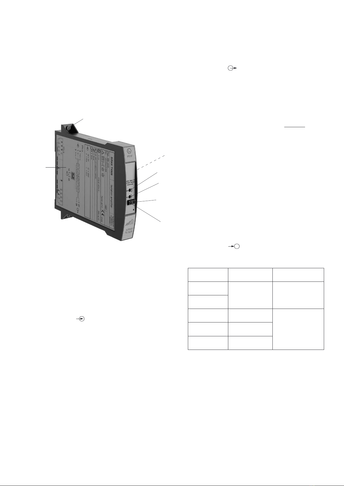
4. Description brève .......................................................10
5. Illustration des éléments fonctionnels ........................10
6. Caractéristiques techniques .......................................10
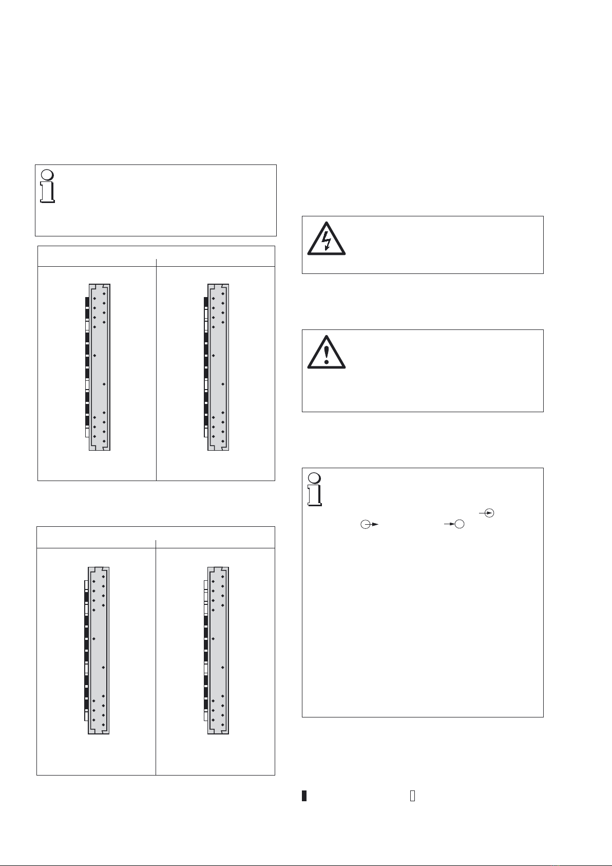
7. Codage mécanique du module embrochable ............11
8. Raccordements électriques .......................................11
9. Ouvrir et fermer l’appareil ...........................................12
10. Configuration du l’amplificateur de séparation ..........12
11. Montage .....................................................................13
12. Mise en service ...........................................................13
13. Entretien .....................................................................13
14. Instructions pour le démontage .................................13
15. Croquis d’encombrement ...........................................13
16. Certificat de conformité ..............................................19
1. A lire en premier, ensuite …
Pour un fonctionnement sûr et sans dan-
ger, il est essentiel de lire le présent mode
d’emploi et de respecter les recomman-
dations de sécurité mentionnées dans les
rubriques
7. Codage mécanique du module
embrochable
8. Raccordements électriques
11. Montage
12. Mise en service.
Ces appareils devraient uniquement être manipulés par
des personnes qui les connaissent et qui sont autorisées
à travailler sur des installations techniques du réglage.
L’appareil ne doit être ouvert que pour la configurati-
on, comme décrit au chapitre «10. Configuration du
l’amplificateur de séparation»!
En cas d’intervention plus poussée, la garantie d’usine
s’éteint!
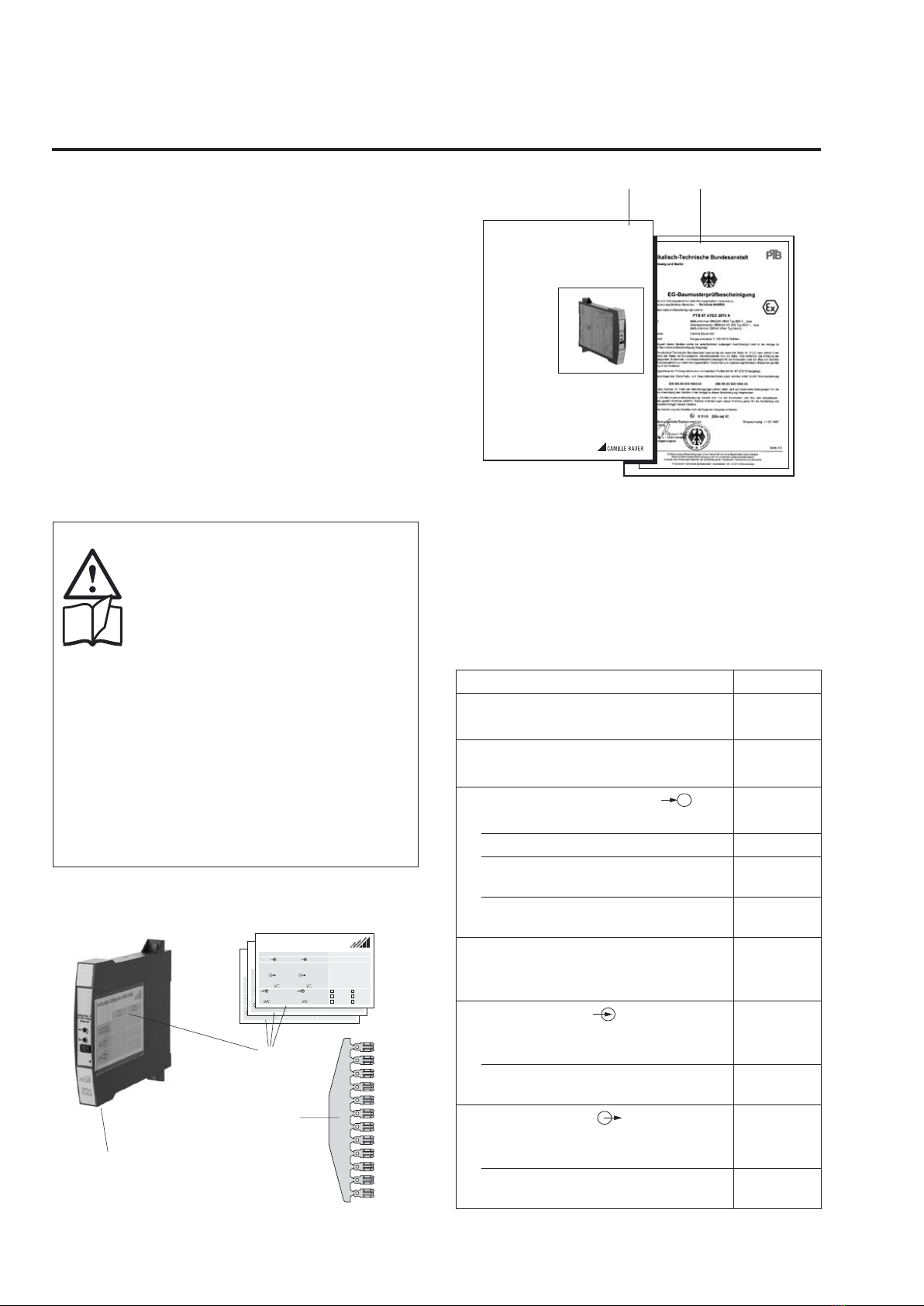
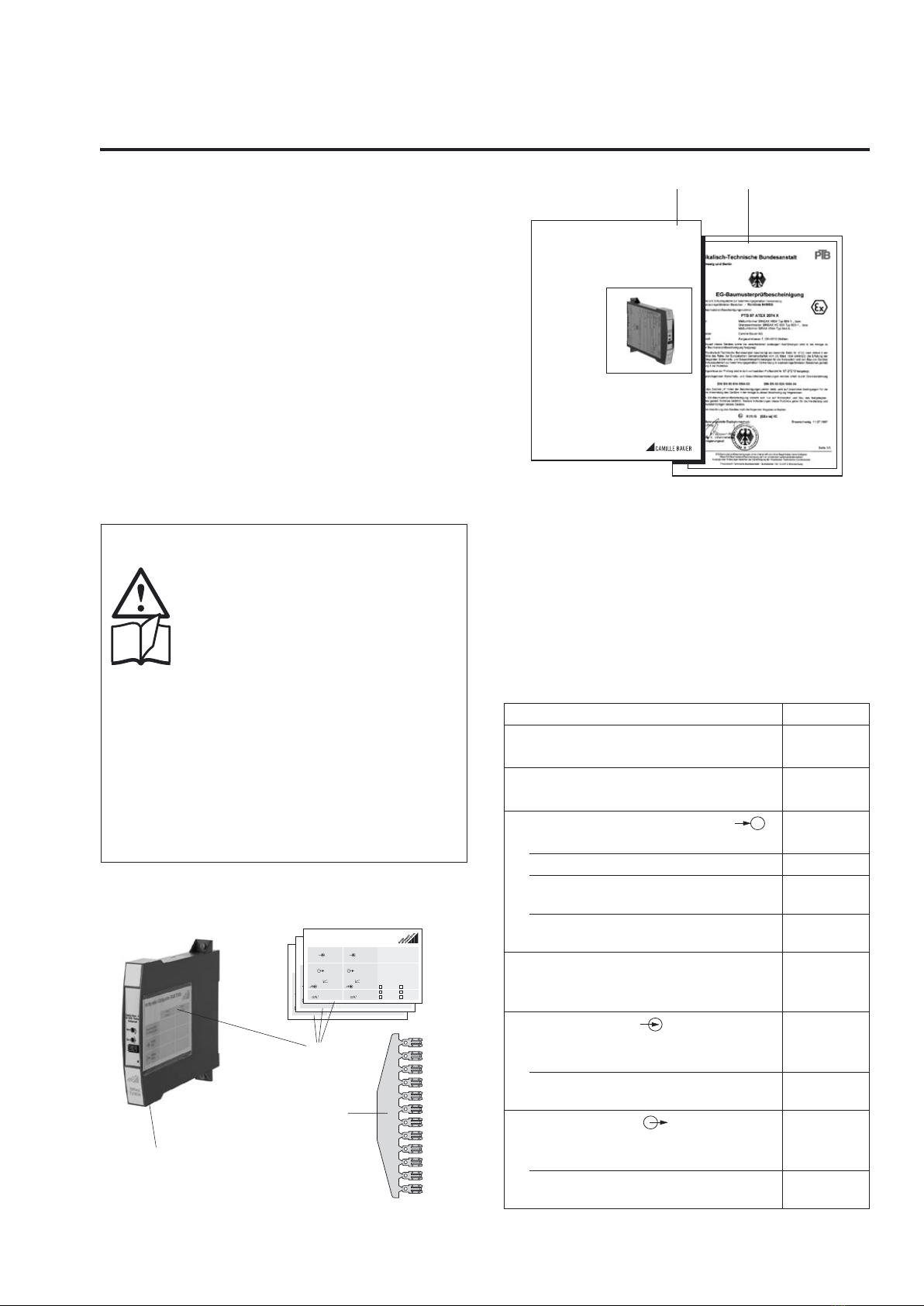
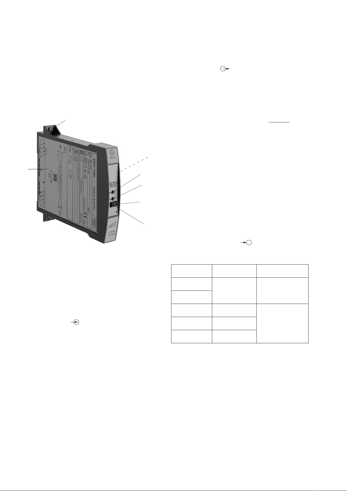
2. Etendue de la livraison (Fig. 1)
(1)
(3)
GOSSEN
METRAWATT
CAMILLE BAUER
Konfiguration / Configuration SIRAX TV 808
Kanal 1
Channel 1
Kanal 2
Channel 2
Eingang
Input
Ausgang
Output
Anlage/Mess-Stelle
Plant/Measuring point
GOSSEN
METRAWATT
CAM ILLE BAUER
Konfiguration / Configuration SIRAX TV 808
Kanal 1
Channel 1
Kanal 2
Channel 2
Eingang
Input
Ausgang
Output
Anlage/Mess-Stelle
Plant/Measuring point
GOSSEN
METRAWATT
CAMILLE BAUER
Anlage/Mess-Stelle
Messeingang
Fühlertyp
Temperatur-Messbereich
Messausgang
Anfahr-Festwert währ. 5 s
Einstellzeit
Bruchsignalisierung
Netzbrumm-Unterdrückung
Grenzwertfunktion
Konfiguration / Configuration SIRAX V 644
Plant/Measuring point
Measuring input
Sensor type
Temperature range
Measuring output
Start up value during 5 s
Setting time
Open-circ. superv.
Mains ripple suppression
Output contact
inactive
50 Hz
inactive
active
60 Hz
active
(2)
(5) (4)
Aargauerstrasse 7
CH-5610 Wohlen/Switzerland
Telefon +41 56618 21 11
Telefax +41 56618 24 58
Telex 827 901 cbm ch
TV 808-61 B d-f-e 125 171 09.97
Betriebsanleitung
Trennverstärker SIRAX TV 808-61
Mode d’emploi
Amplificateur-Séparateur SIRAX TV 808-61
Operating Instructions
Isolating amplifier SIRAX TV 808-61
Amplificateur de séparation (1)
3 Fiches d’informations (2) (pour noter les caractéristi-
ques configurées)
1 Barre de codage (3)
(pour le codage du support d’appareils SIRAX BP 902)
1 Attestation de conformité (4) (seulement pour appareils
en exécution Ex)
1 Mode d’emploi (5) en trois langues: allemand, français
et anglais
3. Références de commande
CARACTERISTIQUE CODE
1. Construction
Boîtier B17 808 - 6
2. Nombre des canaux
1 canal 1
3. Exécution / Alimentation aux.
Standard, 24 … 60 V CC/CA 1
Standard, 85 … 230 V CC/CA 2
[EEx ia] IIC, 24 … 60 V CC/CA
Entrée à sécurité intrinsèque 3
[EEx ia] IIC, 85 … 110 V CC/230 V CA
Entrée à sécurité intrinsèque 4
4. Fonction
1 entrée, 1 sortie en séparation galva-
nique 1
5. Signal d’entrée
Entrée [V]
selon plaquette signalétique 9
Entrée [mA]
selon plaquette signalétique Z
6. Signal de sortie
Sortie [V]
selon plaquette signalétique 9
Sortie [mA]
selon plaquette signalétique Z

10
4. Description brève
L’amplificateur de séparation actif SIRAX TV 808 sert à la
séparation galvanique de signaux d’entrée et de sortie ou
à leur amplification et/ou à leur transformation en un autre
niveau ou genre de signal (courant ou tension).
5. Illustration des éléments fonctionnels
La Fig. 2 présente les parties les plus importantes d’ampli-
ficateur de séparation qui sont décrites ci-après et qui con-
cernent les raccordements électriques et les autres détails
mentionnés dans le présent mode d’emploi.
Fig. 2
(2) Fiche d’information
(6) Plaquette signalétique
(7) Fixation rapide
Diode luminescente rouge sans fonction
ON Diode luminescente verte pour état des fonctionnement
6. Caractéristiques techniques
Entrée de mesure
Courant continu: Etendues standards
0…20 mA, 4…20 mA, ± 20 mA
Valeurs limites 0…0,1 à 0…50 mA
également live-zéro,
valeur début > 0 à ≤ 50% valeur fin
– 0,1…0…+ 0,1 à
–50…0…+ 50 mA
également bipolaire asymétrique
Ri = 15 Ω
Tension continue: Etendues standards
0…10 V, 2…10 V, ± 10 V
Valeurs limites
0…0,06 à 0…40, Ex max. 30 V
également live-zéro,
valeur début > 0 à ≤ 50% valeur fin
– 0,06…0…+ 0,06 à
–40…0…+ 40 V,
Ex max. – 30…0…+ 30 V
Ri = 100 kΩ
(7)
(6)
ON
(2)
Span
Zéro
sans
fonction
Surcharge: Courant continu
en permanence 2 fois
Tension continue
en permanence 2 fois
Sortie de mesure
Courant continu: Etendues standards
0…20 mA, 4…20 mA, ± 20 mA
Valeurs limites 0…1 à 0…20 mA
0,2…1 à 4…20 mA
– 1…0…+ 1 à –20…0…+ 20 mA
Tension de charge: 12 V
Rext max. [kΩ] = 12 V
IAN [mA]
IAN = Val. fin. du courant de sortie
Tension continue: Etendues standards
0…10 V, 2…10 V, ± 10 V
Valeurs limites 0…1 à 0…10 V
0,2…1 à 2…10 V
– 1…0…+ 1 à –10…0…+ 10 V
Charge: ≥ 2 kΩ
Limitation du courant
en Rext max.: Env. 1,1 × IAN pour sortie en cou-
rant
Limitation de tension
en Rext = ∞: Env. 13 V
Ondulation résiduelle
du signal de sortie: < 0,5% p.p.
Temps de réponse: < 50 ms
Alimentation auxiliaire H
Bloc d’alimentation tous-courants (CC et 45...400 Hz)
Tableau 1: Tensions nominales et tolérances
Tension
nominale UN
Tolérance Exécution des
appareils
24... 60 V
CC / CA CC – 15...+ 33%
CA ± 15%
Standard
(Non-Ex)
85...230 V 1
CC / CA
24... 60 V
CC / CA
CC – 15...+ 33%
CA ± 15% En mode de
protection
«Sécurité
intrinsèque»
[EEx ia] IIC
85...230 V
CA ± 10%
85...110 V
CC –15...+ 10%
1 Pour une alimentation auxiliaire > 125 V CC, il faut équiper le circuit
d’alimentation d’un fusible externe avec un pouvoir de coupure de
≤ 20 A CC.
Consommation: ≤ 1,2 W resp. ≤ 3 VA
Précision (en analogie avec DIN/CEI 770)
Précision de base: Limite d’erreur ≤ ± 0,2%
Erreurs types de linéarité et de
reproductibilité comprises
Ambiance extérieure
Mise en service: – 10 à + 40 °C
Température de
fonctionnement: – 25 à + 40 °C,
Ex – 20 à + 40 °C
Température de
stockage: – 40 à + 70 °C
Résistance extérieure:

11
8. Raccordements électriques
L’amplificateur de séparation SIRAX TV 808 est embroché
dans un support d’appareils BP 902. Les connexions élec-
triques entre l’amplificateur de séparation et le support sont
assurées par un connecteur à 96 pôles (forme C, DIN 41 612).
Le plan des fiches utilisées est représenté dans la Fig. 5.
Le schéma de raccordement du support d’appareils peut
être consulté dans notre mode d’emploi BP 902.
Lors du raccordement des câbles, se rassurer
impérativement que toutes les lignes soient
hors tension!
Danger imminent de 230 V alimentation
auxiliaire!
Pour les appareils en mode de protection
à «sécurité intrinsèque» [EEx ia] IIC il faut
respecter les indications contenues dans
l’attestation de conformité ainsi que les
prescriptions nationales pour la réalisation
d’installations électriques dans des enceintes
avec danger d’explosions.
Veuiller en plus, …
… que les caractéristiques techniques qui per-
mettent de résoudre le problème de mesure
correspondent aux données mentionnées sur
la plaquette signalétique du SIRAX TV 808 (
entrée de mesure, sortie de mesure,
alimentation auxiliaire!).
… que la résistance totale du circuit de sortie
de mesure (instruments récepteurs connectés
en série plus résistance des lignes) n’excède
pas la valeur maximum! Rext mentionnée sous
«Sortie de mesure» du chapitre «6. Caractéris-
tiques techniques»!
… que les lignes d’entrée de mesure et de sortie
de signal de mesure soient réalisées par des câbles
torsadés et disposées à une certaine distance des
lignes courant fort!
Au reste, respecter les prescriptions nationales
pour l’installation et le choix du matériel des
conducteurs électriques!
Légende pour les Figs. 3 et 4:
= Avec bouchon de codage,
= Sans bouchon de codage
Humidité relative en
moyenne annuelle: ≤ 75%
Altitude: 2000 m max.
Utiliser seulement dans les intérieurs!
7. Codage mécanique du module
embrochable
En cas de risque d’embrocher les appareils dans
une place inappropriée, la norme EN 50020,
chapitre 6.3.2 prescrit l’élimination de ce risque.
A cette fin, les modules embrochables SIRAX
comportent d’office des bouchons de codage
selon Fig. 3 et 4.
Type de commande
808-611 808-612
Alimentation auxiliaire
24…60 V CC/CA
A
B
C
D
E
F
G
H
I
K
L
M
Face arrière
A
B
C
D
E
F
G
H
I
K
L
M
Face arrière
Alimentation auxiliaire
85…230 V CC/CA
Fig. 3. Codage du module embrochable SIRAX TV 808 en exécu-
tion standard (non-Ex).
Type de commande
808-613 808-614
Alimentation auxiliaire
24…60 V CC/CA
A
B
C
D
E
F
G
H
I
K
L
M
Face arrière
A
B
C
D
E
F
G
H
I
K
L
M
Face arrière
Alimentation auxiliaire
85…110 V CC /
85…230 V CA
Fig. 4. Codage du module embrochable SIRAX TV 808 en
exécution [EEx ia] IIC.

12
Légende pour Fig. 5:
E = Entrée de mesure
A = Sortie de mesure
H = Alim. auxiliaire
H
(+) ~
(–) ~
Face arrière
cab
2
3
4
5
6
7
8
14
20
26
27
28
29
30
31
32
1
A
–
–
I+
+
U+
E
Fig. 5. Plan des fiches. Vue depuis l’arrière du SIRAX TV 808-61.
9. Ouvrir et fermer l’appareil
Fig. 6. Ouvrir l’appareil.
Le boîtier est composé d’une coque (8) et d’un couvercle
(9). Les deux parties sont fixées ensemble par des cliquets.
Pour ouvrir le boîtier, enfoncer successivement à l’aide d’un
tournevis les cliquets (10) et (11) tout en soulevant légèrement
le couvercle du côté des prises, jusqu’à ce que les cliquets
se débloquent.
Pour fermer l’appareil, introduire les languettes de guidage
et légèrement presser ensemble les deux parties jusqu’à ce
que les cliquets soient en place.
10. Configuration du l’amplificateur de sépa-
ration
Pour la configuration du SIRAX TV 808, il faut ouvrir l’appareil
(voir rubrique «9. Ouvrir et fermer l’appareil»).
(8)
(9)
(11)
(10)
10.1 Variante du signal de sortie
(«sortie tension» ou «sortie courant»)
En fonction du positionnement «U» ou «I» des cavaliers ST 4
et ST 3, il est possible de modifier le signal de «sortie tension»
en signal de «sortie courant» ou vice versa (Fig. 7).
Sortie
Cavaliers
ST 4 ST 3
Courant [mA]
Tension [V] U I
U I
U I
U I
10.2 Entrées et sorties normalisées
En fonction des 2 dès 6 cavaliers B1 à B6 en place, il est
possible de modifier, pour les valeurs normalisées, le signal
d’entrée et le signal de sortie, ceci sans influence la précision
de l’appareil et à condition de ne pas agir sur les potentio-
mètres de réglage du «Span» et «Zero».
4…20
mA
0…20
mA
–20…20
mA
2…10
V
0…10
V
–10…10
V
4…20 mA B1,B4 B2,B4 B3,B4 B1,B4 B2,B4 B3,B4
0…20 mA B1,B5 B2,B5 B3,B5 B1,B5 B2,B5 B3,B5
–20…20 mA B1,B6 B2,B6 B3,B6 B1,B6 B2,B6 B3,B6
2…10 V B1,B4 B2,B4 B3,B4 B1,B4 B2,B4 B3,B4
0…10 V B1,B5 B2,B5 B3,B5 B1,B5 B2,B5 B3,B5
–10…10 V B1,B6 B2,B6 B3,B6 B1,B6 B2,B6 B3,B6
Les appareils en stock sont configurés avec signal d’entrée
en 0 … 20 mA. Les cavaliers B2 et B5 sont en place et les
cavaliers ST 4 et ST 3 sont placés en position «I».
B1
B2
B3
B4
B5
B6
U I U I
ST3
ST4
Span
Zéro
Fig. 7. Disposition des cavaliers ST 4 et ST 3, B1 à B6 et des
potentiomètres de réglage du «Span» et «Zéro».

13
11. Montage
L’amplificateur de séparation SIRAX TV 808 est embroché
dans un support d’appareils BP 902.
Pour la détermination de l’endroit de montage
(endroit de mesure) il faut faire attention que les
valeurs limites de la température de fonctionne-
ment ne soient pas dépassées:
– 25 et + 40 °C pour appareils standard
– 20 et + 40 °C pour appareils en Ex!
11.1 Monter le module embrochable dans un sup-
port d’appareils
Avant d’embrocher le SIRAX TV 808 dans le
support d’appareils, vérifier sans faute …
… la concordance des raccordements élec-
triques du support et du plan de bornes du
module embrochable
… le codage correct du support d’appa-
reils selon chapitre «Codage mécanique
du support d’appareils». Respecter les
indications du mode d’emploi du support
d’appareils.
… que pour des modules embrocha-
bles SIRAX avec alimentation auxiliaire
24…60 V CC/CA, le bouchon de codage B
du support d’appareils soit enlevé et que
la source d’alimentation fournisse la faible
tension correcte.
1. Enficher le module embrochable.
2. Amener la fixation rapide dans la position verticale pour
montage vertical de l’appareil, dans la position horizontale
pour montage horizontal.
3. Enfoncer à l’aide d’un tournevis la fixation rapide jusqu’à
ce que l’on entende l’encliquetage.
SIRAX
3.
GOSSEN
METRAWATT
CAMILLE BAUER
SIRAX
1.
2.
Fig. 8. Enficher le module embrochable.
12. Mise en service
Enclencher le circuit d’entrée de mesure et l’alimentation
auxiliaire. Après l’enclenchement de la tension auxiliaire, la
diode verte reste allumée en permanence.
Lors de l’enclenchement de l’énergie auxiliaire de
l’amplificateur de séparation, la source d’alimen-
tation doit fournir pendant un court laps de temps
en courant suffisamment élevé, ceci du fait que le
SIRAX TV 808 nécessite un courant de démarrage
Idémarrage de …
… Idémarrage ≥ 160 mA pour la version avec le bloc
d’alimentation auxiliaire 24 – 60 V CC/CA
ou
… Idémarrage ≥ 35 mA pour la version avec le bloc
d’alimentation auxiliaire 85 – 230 V CC/CA
13. Entretien
L’amplificateur de séparation ne nécessite pas d’entretien.
14. Instructions pour le démontage
1. Tourner la fixation rapide de 90°.
2. Retirer le module embrochable.
SIRAX
2.
1.
Fig. 9. Retirer le module embrochable.
15. Croquis d’encombrement
110
135,7 15 18
103,3
123,5
113,5
150,7
+0
– 0,5
Fig. 10. SIRAX TV 808 en boîtier B17.

14
Operating Instructions
Isolating amplifier SIRAX TV 808-61
Contents
1. Read first and then... ................................................. 14
2. Scope of supply .........................................................14
3. Ordering informations .................................................14
4. Brief description .........................................................15
5. Overview of the parts .................................................15
6. Technical data ............................................................15
7. Mechanical coding of the plug-in module ..................16
8. Electrical connections ................................................16
9. Withdrawing and inserting the device ........................17
10. Configuration of the isolating amplifier ......................17
11. Mounting ....................................................................18
12. Commissioning ...........................................................18
13. Maintenance ...............................................................18
14. Releasing the isolation amplifier .................................18
15. Dimensional drawing ..................................................18
16. Declaration of conformity ...........................................19
1. Read first and then …
The proper and safe operation of the device
assumes that the Operating Instructions
are read and the safety warnings given in
the various Sections
7. Mechanical coding of the
plug-in module
8. Electrical connections
11. Mounting
12. Commissioning
are observed.
The device should only be handled by appropriately trained
personnel who are familiar with it and authorised to work
in electrical installations.
The instrument must only be opened for configuration,
as described in section “10. Configuration of the isolating
amplifier”!
The guarantee is no longer valid if the instrument is further
tampered with!
2. Scope of supply (Fig. 1)
(1)
(3)
GOSSEN
METRAWATT
CAMILLE BAUER
Konfiguration / Configuration SIRAX TV 808
Kanal 1
Channel 1
Kanal 2
Channel 2
Eingang
Input
Ausgang
Output
Anlage/Mess-Stelle
Plant/Measuring point
GOSSEN
METRAWATT
CAM ILLE BAUER
Konfiguration / Configuration SIRAX TV 808
Kanal 1
Channel 1
Kanal 2
Channel 2
Eingang
Input
Ausgang
Output
Anlage/Mess-Stelle
Plant/Measuring point
GOSSEN
METRAWATT
CAM ILLE BAUER
Anlage/Mess-Stelle
Messeingang
Fühlertyp
Temperatur-Messbereich
Messausgang
Anfahr-Festwert währ. 5 s
Einstellzeit
Bruchsignalisierung
Netzbrumm-Unterdrückung
Grenzwertfunktion
Konfiguration / Configuration SIRAX V 644
Plant/Measuring point
Measuring input
Sensor type
Temperature range
Measuring output
Start up value during 5 s
Setting time
Open-circ. superv.
Mains ripple suppression
Output contact
inactive
50 Hz
inactive
active
60 Hz
active
(2)
(5) (4)
Aargauerstrasse 7
CH-5610 Wohlen/Switzerland
Telefon +41 56618 21 11
Telefax +41 56618 24 58
Telex 827 901 cbm ch
TV 808-61 B d-f-e 125 171 09.97
Betriebsanleitung
Trennverstärker SIRAX TV 808-61
Mode d’emploi
Amplificateur-Séparateur SIRAX TV 808-61
Operating Instructions
Isolating amplifier SIRAX TV 808-61
Isolating amplifier (1)
3 Data cards (2) (for recording configured settings)
1 Coding comb (3)
(for coding the backplane SIRAX BP 902)
1 Type Examination Certificate (4) (for Ex version devices
only)
1 Operating Instructions (5), in three languages: German,
French, English
3. Ordering informations
DESCRIPTION MARKING
1. Mechanical design
Housing B17 808 - 6
2. Number of channel
1 channel 1
3. Version / Power supply
Standard, 24 … 60 V DC/AC 1
Standard, 85 … 230 V DC/AC 2
[EEx ia] IIC, 24 … 60 V DC/AC
Input intrinsically safe 3
[EEx ia] IIC, 85 … 110 V DC/230 V AC
Input intrinsically safe 4
4. Function
1 input, 1 electrically insulated output 1
5. Input signal
Input [V]
acc. to type label 9
Input [mA]
acc. to type label Z
6. Output signal
Output [V]
acc. to type label 9
Output [mA]
acc. to type label Z

15
4. Brief description
The purpose of the isolating amplifier SIRAX TV 808 is to
electrically insulate input and output signals, respectively
to amplify and/or change the signal level or type (current or
voltage) of the input signals.
5. Overview of the parts
Figure 2 shows those parts of the device of consequence
for electrical connections and other operations described in
the Operating Instructions.
Fig. 2
(2) Data card
(6) Type label
(7) Fastener
Red LED without function
ON Green LED for indicating device standing by
6. Technical data
Measuring input
DC current: Standard ranges
0…20 mA, 4…20 mA, ± 20 mA
Limit values 0…0.1 to 0…50 mA
also live-zero,
start value > 0 to ≤ 50% final value
– 0.1…0…+ 0.1 to
– 50…0…+ 50 mA
also bipolar asymmetrical
Ri = 15 Ω
DC voltage: Standard ranges
0…10 V, 2…10 V, ± 10 V
Limit values
0…0.06 to 0…40, Ex max. 30 V
also live-zero,
start value > 0 to ≤ 50% final value
– 0.06…0…+ 0.06 to
–40…0…+ 40 V,
Ex max. – 30…0…+ 30 V
Ri = 100 kΩ
(7)
(6)
ON
(2)
Span
Zero
without
function
Overload: DC current
continuously 2-fold
DC voltage
continuously 2-fold
Measuring output
DC current: Standard ranges
0…20 mA, 4…20 mA, ± 20 mA
Limit values
0…1 to 0…20 mA
0.2…1 to 4…20 mA
– 1…0…+ 1 to – 20…0…+ 20 mA
Burden voltage: 12 V
Rext max. [kΩ] = 12 V
IAN [mA]
IAN = Output circuit full-scale value
DC voltage: Standard ranges
0…10 V, 2…10 V, ± 10 V
Limit values
0…1 to 0…10 V
0.2…1 to 2…10 V
– 1…0…+ 1 to – 10…0…+ 10 V
Burden: ≥ 2 kΩ
Current limiter at
Rext max.: Approx. 1.1 × IAN for current out-
put
Voltage limiter at
Rext = ∞: Approx. 13 V
Residual ripple in
output current: < 0.5% p.p.
Response time: < 50 ms
Power supply H
AC/DC power pack (DC and 45...400 Hz)
Table 1: Nominal voltages and tolerances
Nominal
voltage UN
Tolerance Instrument
version
24... 60 V
DC / AC DC – 15...+ 33%
AC ± 15%
Standard
(non-Ex)
85...230 V 1
DC / AC
24... 60 V
DC / AC
DC – 15...+ 33%
AC ± 15% Type of
protection
“Intrinsically safe”
[EEx ia] IIC
85...230 V
AC ± 10%
85...110 V
DC –15...+ 10%
1 For power supply > 125 V, the auxiliary circuit should include an
external fuse with a rating ≤ 20 A DC.
Power input: ≤ 1.2 W resp. ≤ 3 VA
Accuracy data (acc. to DIN/IEC 770)
Basic accuracy: Limit error ≤ ± 0.2%
Including linearity and reproducibility
errors
Environmental conditions
Commissioning
temperature: – 10 to + 40 °C
Operating temperature: – 25 to + 40 °C,
Ex – 20 to + 40 °C
Storage temperature: – 40 to + 70 °C
External resistance:

16
8. Electrical connections
The isolating amplifier SIRAX TV 808 is plugged onto a
backplane BP 902. A 96 pin connector (model C, DIN 41 612)
establishes the electrical connections between the isolating
amplifier and the backplane. The pin connections can be
seen from Fig. 5.
Please refer to our backplane instructions for the back-
plane wiring.
Make sure that the cables are not live when
making the connections!
The 230 V power supply is potentially
dangerous!
In the case of “Intrinsically safe” explosion-
proof versions [EEx ia] IIC, the supplementary
information given on the Type Examination
Certificate and also local regulations appli-
cable to electrical installations in explosion
hazard areas must be taken into account.
Also note that, …
… the data required to carry out the prescribed
measurement must correspond to those marked
on the nameplate of SIRAX TV 808 ( measu-
ring input, measuring output, power
supply!).
… the total loop resistance connected to the
output (receiver plus leads) does not exceed the
maximum permissible value Rext. max., see Meas-
uring output” in Section “5. Technical data” for
the maximum values of Rext.!
… the measurement input and output cables should
be twisted pairs and run as far as possible away
from heavy current cables!
In all other respects, observe all local regulations
when selecting the type of electrical cable and
installing them!
Legend to Figs. 3 and 4:
= With set of code, = Without set of code
Annual mean
relative humidity: ≤ 75%
Altitude: 2000 m max.
Indoor use statement!
7. Mechanical coding of the plug-in module
Where there is a danger of inserting a module in the
wrong slot, the possibility has to be excluded as
prescribed in EN 50 020, Section 6.3.2. To this end,
the units must be supplied already equipped with
coding inserts as shown in Figures 3 and 4.
Order Type
808-611 808-612
Power supply
24…60 V DC/AC
A
B
C
D
E
F
G
H
I
K
L
M
Back
A
B
C
D
E
F
G
H
I
K
L
M
Back
Power supply
85…230 V DC/AC
Fig. 3. Coding of the plug-in module SIRAX TV 808 in standard
(non-Ex) version.
Order Type
808-613 808-614
Power supply
24…60 V DC/AC
A
B
C
D
E
F
G
H
I
K
L
M
Back
A
B
C
D
E
F
G
H
I
K
L
M
Back
Power supply
85…110 V DC /
85…230 V AC
Fig. 4. Coding of the plug-in module SIRAX TV 808 in [EEx ia] IIC
version.

17
Legend for Fig. 5:
E = Measuring input
A = Measuring output
H = Power supply
H
(+) ~
(–) ~
Back
cab
2
3
4
5
6
7
8
14
20
26
27
28
29
30
31
32
1
A
–
–
I+
+
U+
E
Fig. 5. Plug arrangement seen from the rear of SIRAX TV 808-61.
9. Withdrawing and inserting the device
Fig. 6. Withdrawing the device.
There are two parts to the casing, the shell (8) and the cover
(9). The are held together by robust pegs and can be simply
assembled manually. The casing can be opened by press-
ing the pegs (10) and (11) inwards one after another using
a screwdriver and applying pressure to lift the casing cover
on the connector side until the pegs release.
To assemble the casing, insert the guides into the casing
shell and press the two halves together using light pressure
until the pegs snap into place.
10. Releasing the isolation amplifier
The SIRAX TV 808 unit has to be opened before it can be
configured (see Section “9. Withdrawing and inserting the
device”).
(8)
(9)
(11)
(10)
10.1 Type of output signal
(voltage or current)
The output can be configured for a voltage or current signal
by inserting the plug-in jumpers “ST 4” or “ST 3” in position
“U” or “I” (Fig. 7).
Output
Jumpers
ST 4 ST 3
Current [mA]
Voltage [V] U I
U I
U I
U I
10.2 Standard input and output ranges
Two of six plug-in jumpers B1 to B6 are used for selecting
the standard ranges of the isolating amplifiers. Providing the
potentiometers “Span” and “Zero” are not moved, changing
the range has no influence on amplifier accuracy.
4…20
mA
0…20
mA
–20…20
mA
2…10
V
0…10
V
–10…10
V
4…20 mA B1,B4 B2,B4 B3,B4 B1,B4 B2,B4 B3,B4
0…20 mA B1,B5 B2,B5 B3,B5 B1,B5 B2,B5 B3,B5
–20…20 mA B1,B6 B2,B6 B3,B6 B1,B6 B2,B6 B3,B6
2…10 V B1,B4 B2,B4 B3,B4 B1,B4 B2,B4 B3,B4
0…10 V B1,B5 B2,B5 B3,B5 B1,B5 B2,B5 B3,B5
–10…10 V B1,B6 B2,B6 B3,B6 B1,B6 B2,B6 B3,B6
The default setting of the preferred versions ex stock is
0 … 20 mA for input and output, i.e. jumpers are inserted
in positions B2 and B5 and jumpers ST 4 and ST 3 are in
position “I”.
B1
B2
B3
B4
B5
B6
U I U I
ST3
ST4
Span
Zero
Fig. 7. Position of the jumpers ST 4 and ST 3, B1 to B6 and the
potentiometers “Span” and “Zero”

18
11. Mounting
The isolating amplifier SIRAX TV 808 is plugged onto a
backplane BP 902.
When deciding where to install the transmitter
(measuring location), take care that the limits of
the operating temperature are kept:
– 25 and + 40 °C for standard instruments
– 20 and + 40 °C for instruments in Ex version!
11.1 Plugging the module into the backplane
Before inserting the SIRAX TV 808 into the
backplane, ensure that, …
… the backplane wiring is in strict accordance
with the wiring diagram of the module
… the backplane is coded correctly ac-
cording to the section entitled “Mechani-
cal coding of the backplane”. Read the
instructions for the backplane.
… the red coding insert has been removed
from the backplane for SIRAX plug-in
modules with a power supply of 24…60 V
DC/AC and that the power supply is cor-
rect for the module.
1. Clip the module base onto the top-hat rail.
2. If the backplane is mounted vertically, turn the quick release
screws on the module to a vertical position, respectively if
it is mounted horizontally, turn the screws to a horizontal
position.
3. Press the quick release screws inwards with the screwdriver
until there is an audible click.
SIRAX
3.
GOSSEN
METRAWATT
CAMILLE BAUER
SIRAX
1.
2.
Fig. 8. Plug the module into the base.
12. Commissioning
Switch on the measuring input and the power supply. The
green LED lights continuously after switching on.
The power supply unit must be capable of supply-
ing a brief current surge when switching on. The
isolating amplifier presents a low impedance at the
instant of switching which requires a current Istart
of …
… Istart ≥ 160 mA for the version with a power sup-
ply range of 24 – 60 V DC/AC
or
… Istart ≥ 35 mA for the version with a power supply
range of 85 – 230 V DC/AC
13. Maintenance
No maintenance is required.
14. Releasing the isolating amplifier
1. Rotate the quick release screws 90° .
2. Withdraw the plug-in module.
SIRAX
2.
1.
Fig. 9. Withdraw the module from the base.
15. Dimensional drawing
110
135.7 15 18
103.3
123.5
113.5
150.7
+0
– 0.5
Fig. 10. SIRAX TV 808 in housing B17.

19
16. Konformitätserklärung / Certificat de conformité / Declaration of conformity
Standard, nicht-Ex /standard, non-Ex / standard, non-Ex
Di es e Erklä ru ng besc he inigt d ie Ü berei ns timmu ng m it den This de clarati on certif ie s compl ia nce with the above m entione d
genannten R ic ht linien, bei nh al tet jedoch ke in e Zusicherung direc tives b ut does n ot incl ude a pro perty a ssuranc e.
vo n Ei ge ns ch af ten. Die Sicher he it sh in we ise der mitgeli ef er te n The s afety note s given in the prod uct d ocume ntati ons, which a re
Produktdokumentationen sind zu beachten. part of the supply, must be observed.
EG - KONFORMITÄTSERKLÄRUNG
DECLARATION OF CONFORMITY
Dokument-Nr./ TV808NEX.DOC
Document.No.:
Hersteller/ Camille Bauer AG
Manufacturer: Switzerland
Anschrift / Aargauerstrasse 7
Address: CH-5610 Wohlen
Produktbezeichnung/ Tennverstärker
Product name: Isolation amplifier
Typ / Type: SIRAX TV 808
Das bezeichnete Produkt stimmt mit den Vorschriften folgender Europäischer Richtlinien überein,
nachgewiesen durch die Einhaltung folgender Normen:
The above mentioned product has been manufactured according to the regulations of the following
European directives proven through compliance with the following standards:
Nr. / No. Richtlinie / Directive
89/336/EWG
89/336/EEC
Elektromagnetische Verträglichkeit - EMV - Richtlinie
Electromagnetic compatibility -EMC directive
EMV /
EMC
Fachgrundnorm /
Generic Standard
Messverfahren /
Measurement methods
Störfestigkeit /
Immunity
EN 50 082-2 : 1994 IEC 1000-4-2 : 1991
IEC 1000-4-3 : 1995
IEC 1000-4-4 : 1988
IEC 1000-4-5 : 1995
IEC 1000-4-6 : 1995
IEC 1000-4-11 : 1993
Nr. / No. Richtlinie / Directive
73/23/EWG
73/23/EEC
Elektrische Betriebsmittel zur Verwendung innerhalb bestimmter Spannungs-
grenzen - Niederspannungsrichtlinie - CE-Kennzeichnung : 95
Electrical equipment for use within certain voltage limits - Low Voltage Direc-
tive - Attachment of CE mark : 95
EN/Norm/Standard IEC/Norm/Standard
EN 61 010-1 : 1993 IEC 1010-1 : 1990 + A1 : 1992
Ort, Datum /
Place, date: Wohlen, den 24. August 1998
Unterschrift / M.Ulrich
Signature: Leiter Entwicklung

20
Eingang Ex / entrée Ex / input Ex
Di es e Erklä ru ng besc he inigt d ie Ü berei ns timmu ng m it den This de clarati on certif ie s compl ia nce with the above m entione d
genannten R ic ht linien, bei nh al tet jedoch ke in e Zusicherung direc tives b ut does n ot incl ude a pro perty a ssuranc e.
vo n Ei ge ns ch af ten. Die Sicher he it sh in we ise der mitgeli ef er te n The s afety note s given in the prod uct d ocume ntati ons, which a re
Produktdokumentationen sind zu beachten. part of the supply, must be observed.
EG - KONFORMITÄTSERKLÄRUNG
DECLARATION OF CONFORMITY
Dokument-Nr./ TV808EIG.DOC
Document.No.:
Hersteller/ Camille Bauer AG
Manufacturer: Switzerland
Anschrift / Aargauerstrasse 7
Address: CH-5610 Wohlen
Produktbezeichnung/ Trennverstärker
Product name: Isolating amplifier
Typ / Type: SIRAX TV 808 Eingang EX
Das bezeichnete Produkt stimmt mit den Vorschriften folgender Europäischer Richtlinien überein,
nachgewiesen durch die Einhaltung folgender Normen:
The above mentioned product has been manufactured according to the regulations of the following
European directives proven through compliance with the following standards:
Nr. / No. Richtlinie / Directive
89/336/EWG
89/336/EEC
Elektromagnetische Verträglichkeit - EMV - Richtlinie
Electromagnetic compatibility -EMC directive
EMV /
EMC
Fachgrundnorm /
Generic Standard
Messverfahren /
Measurement methods
Störaussendung /
Emission
EN 50 081-2 : 1993 EN 55011 : 1992
Störfestigkeit /
Immunity
EN 50 082-2 : 1994 IEC 1000-4-2 : 1991
IEC 1000-4-3 : 1995
IEC 1000-4-4 : 1988
IEC 1000-4-5 : 1995
IEC 1000-4-6 : 1995
IEC 1000-4-11: 1993
Nr. / No. Richtlinie / Directive
73/23/EWG
73/23/EEC
Elektrische Betriebsmittel zur Verwendung innerhalb bestimmter Spannungs-
grenzen - Niederspannungsrichtlinie - CE-Kennzeichnung : 95
Electrical equipment for use within certain voltage limits - Low Voltage Direc -
tive - Attachment of CE mark : 95
EN/Norm/Standard IEC/Norm/Standard
EN 61 010-1 : 1993 IEC 1010-1 : 1990 + A1 : 1992
Die explosionsgeschützte Ausführung dieses Produkts stimmt mit der Europäischen Richtlinie
94/9/EG überein.
The explosion protected variant of this product has been manufactured according the European
directive 94/9.
Ort, Datum /
Place, date: Wohlen, den 24. August 1998
Unterschrift / M.Ulrich
Signature: Leiter Entwicklung
Table of contents
Languages:
Other Camille Bauer Amplifier manuals

Camille Bauer
Camille Bauer SIRAX TV 808-62 User manual

Camille Bauer
Camille Bauer SINEAX SV 824 User manual

Camille Bauer
Camille Bauer SINEAX TV 809 User manual

Camille Bauer
Camille Bauer GOSSEN METRAWATT SINEAX TV 808-115 User manual

Camille Bauer
Camille Bauer SINEAX TV 808-12 User manual

Camille Bauer
Camille Bauer SINEAX TV 808-115 User manual

Camille Bauer
Camille Bauer SINEAX TV815 User manual

Camille Bauer
Camille Bauer SINEAX TV 808-11 User manual

Camille Bauer
Camille Bauer SINEAX TV 809 User manual