Glass Ware Aikido Stereo 5687 PCB User manual

DANGER!
This PCB holds a high-voltage power supply; thus, a real
—
and possibly—lethal shock hazard exists.
Ideally, a variac should be used to slowly power up the
regulator, as it is better to have a mis-
oriented electrolytic
capacitor or a mis-located re
sistor blow at low voltages,
rather than at high voltages. Remember that the danger
increases by the square of the voltage; for example, 200
volts is four times more dangerous than 100 volts
and 400
volts is sixteen times more dangerous.
Once the power supply is powered up
, be cautious at all
times. In fact,
even when the power supply is disconnected
or shut down, assume that power-supply
capacitors will have
retained their charge and, thus, can still shock
. If you are not
an experienced electrical practitioner, before
attaching the
transformer windings to the board,
have someone who is
well
-experienced in electronics review your work.
There are too few tube-
loving solder slingers left; we cannot
afford to lose any more.
AUDIO DESIGN
www.glass-ware.com
www.tubecad.com
sales@glass-ware.com
Copyright © 2009-2011
All Rights Reserved
GlassWare

Warning!
This PCB contains a high-voltage power supply; thus, a real and lethal
shock hazard
exists. Once the power transformer
is attached, be cautious at all times. In fact, always
assume that the high voltage capacitors will have retained their charge e
ven after the
power supply has been
disconnected or shut down. If you are not an experienced
electrical practitioner, before applying the AC
voltage have someone who is
experienced review your work. There are too few tube-
loving solder slingers left; we
cannot afford to lose any more. Overview
Thank you for your purchase of the GlassWare Aikido 5687 All in One 9-
pin stereo
PCB. This FR-
4 PCB is extra thick, 0.094 inches (inserting and pulling tubes from their
sockets won’t bend or break this board), double-sided, with plated-through heavy
2oz
copper traces. In addition, the PCB is lovingly an d expensively
made in the USA. The
board is 7 by 6 inches, with five mounting holes, which helps
to prevent excessive PCB
bending while inserting and pulling tubes from their sockets.
Each PCB holds two Aikido line-
stage amplifiers; thus, one board is all that is needed
for stereo unbalanced use (or one board for one channel of balanced amplification).
By
including the necessary components for the heater and high volta
ge B+ power supplies
on the PCB, the5687 All in One board makes building a standard-
setting line stage
amplifier a breeze. This assembled board with a chassis, volume control, selector
switch, power transformer, and a fistful of RCA jacks is all that is needed.
PCB Features
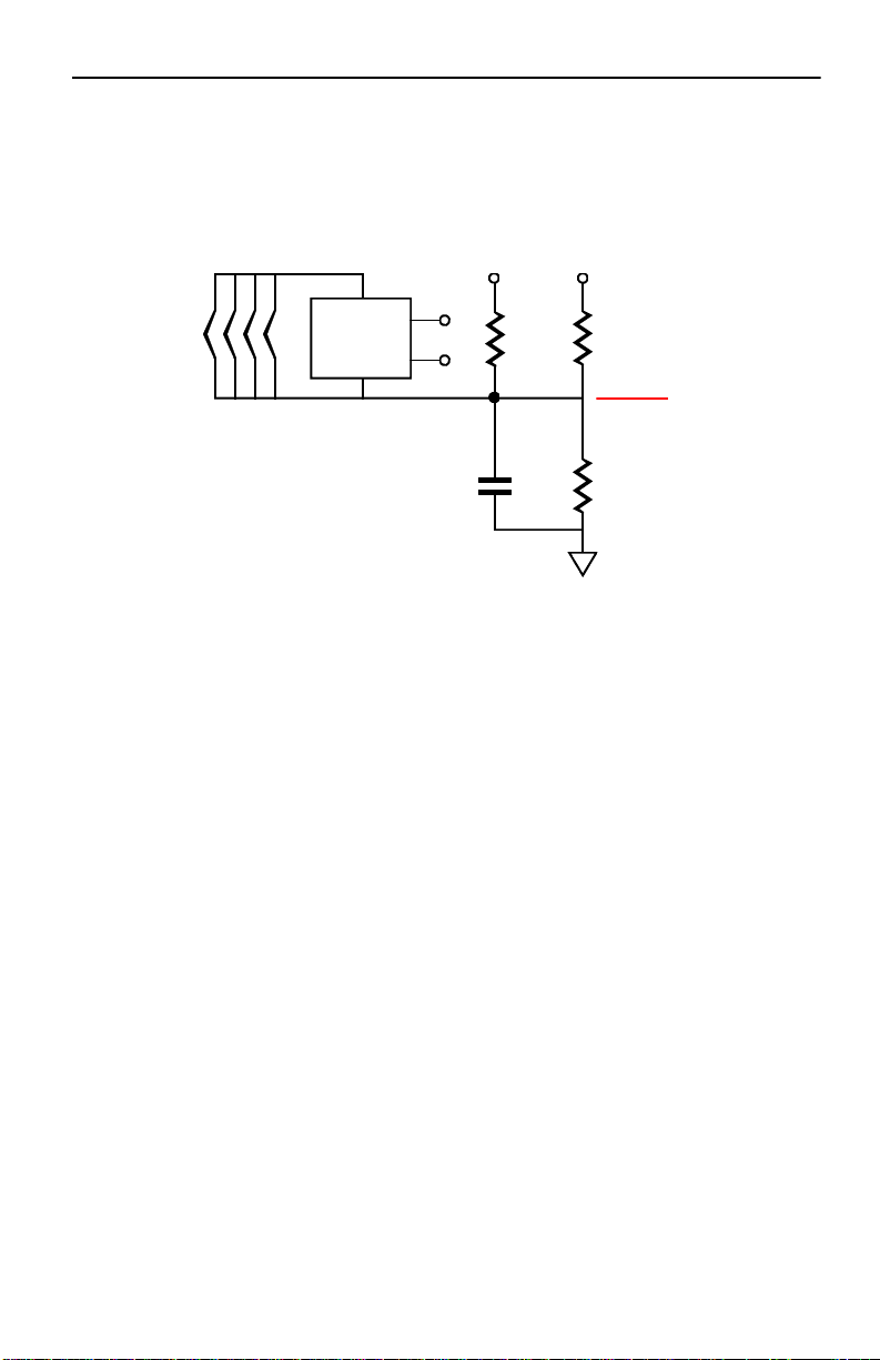
B+ and Heater Power Supplies On the 5687 All in One board, two power su
pplies
reside, one for the high-voltage B+ for the tubes and a low-
voltage power supply for the
heaters. The high-voltage power supply uses an RC filter to smooth
away ripple, while
the low-voltage power supply uses an LDO
voltage regulator to provide a stable and
noise-
free voltage output. The power supplies require an external power transformer(s)
with two secondary windings, one for the B+ voltage and one for the heater
power
supply.
Redundant Solder Pads This board holds two sets of differently-
spaced solder pads
for each critical resistor, so that radial and axial resistors can easily be used (
radial
bulk-foil resistors and axial
film resistors, for example). In addition, most capacitor
locations find many redundant solder pads, so wildly differing-
sized coupling
capacitors can be placed neatly on the board, without excessively bending their leads.
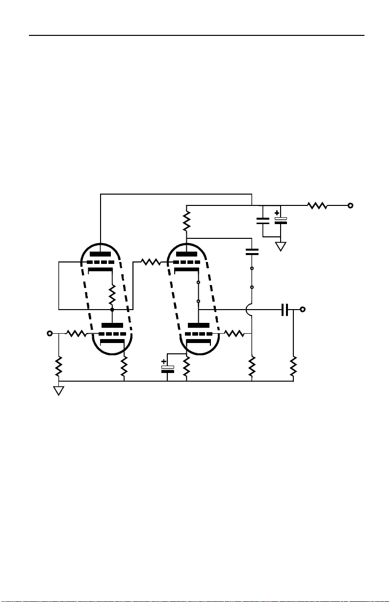
Two Output-Stage Topologies The output stage can
be configured either as the classic
Aikido line amplifier or as an Aikido headphone amplifier. The 5687 is a robust
triode
that can deliver a lot of current at relatively low voltage
s, making it ideal for driving
headphones or other low-impedance loads.
Power-Supply-Decoupling Capacitors The 5687 All in One
PCB provides space for
two sets of capacitors to decouple both Aikido gain stages from the B+ connection and
each other. This arrangement allows a large-valued electrolytic capacitor and small
-
valued film capacitor to be used in parallel, while a series voltage-
dropping resistor
completes the RC filter.
GlassWare Audio Design

2
The
Aikido
amplifier delivers the sonic goods. It offers low distortion, low output
impedance, a great PSRR figure, and feedback- free amplification. The secret to it
s
superb performance— despite not using global feedback—
lies in its internal symmetry,
whic
h balances imperfections with imperfections. As a result, the Aikido circuit
works
at least a magnitude better than the equivalent SRPP or grounded-cathode amplifier.
Aikido Amplifier
B+
Rk
Rk
in
out
R2
R1
Rk
Rk
C
5687
Rg
Rgs
Rgs
Introduction to the Aikido
Universal Topology
In
the schematic
above
, the
5687
triodes are
specified
as an
example only, as 300B
and 845 triodes could be used to make an Aikido amplifier.
The circuit does not rely on these triodes or any other specif
ic triodes to work
correctly. It’s the topology, not the tubes that make the Aikido special. (Far too m
any
believe that a different triode equals a different topology; it doesn't. Making this
mistake would be like thinking that the essential aspect of being a seeing-
eye dog
rested in being a Golden Lab.)
Low Distortion For example, the Aikido
circuit produces far less distortion than
comparable circuits by using the triode’s own nonlinearity against itself
. The triode is
not as linear as a resistor so,
ideally, it should not see a linear load, but a
corresponding, complementary, balancing non-
linear load. An analogy is found in
someone needing eye
glasses; if the eyes were perfect, then perfectly flat (perfectly
linear) lenses would
be needed, whereas imperfect eyes need counterbalancing lenses
(non-linear lenses) to see clearly. Now, loading a triode with the same triode—
under
the same cathode-to-plate voltage and idle current and with the same cathode resistor—
works well to flatten the transfer curve out of that triode.
PSRR The
Aikido circuit sidesteps power supply noise by incorporating the noise into
its normal operation. The improved PSRR advantage is important, for it greatly
unburdens the power-supply. With no tweaking or tube
selecting, you should easily be
able to get a -30dB PSRR figure (a conventional grounded-
cathode amplifier with the
same tubes and current draw yields only a -6dB PSRR); and
with some tweaking of
resistor R1’s value, -60dB—or more—is possible. Additionall
y, unless regulated power
supplies are used for the plate and heater, these critical voltages will vary as
the power
line’s voltage falls and climbs with your house’s and neighbors’ house’s use
, usually
throwing the supposedly fixed wall-voltage askew. Nev
ertheless, the Aikido amplifier
will still function flawlessly, as it tracks these voltage changes symmetrically.
Aikido 5687 Stereo All-In-One PCB
5687
56875687

GlassWare Audio Design 3
Age
Tolerant
Remember
, tubes are not yardsticks, being more like car tires
—
they
wear out. Just as a tire’s weight and diameter decrease over time, so does a
tube’s
conductance. In other words, a fresh 5687 is not the same as that same 5687
after
2,000 hours of use. But as long as the two triodes within the 5687
age in the same
way—which they are inclined to do—
the Aikido amplifier will always bias up
correctly, splitting the B+ voltage between the triodes.
No Negative Feedback Loop The Aikido topology d
oes not use any negative
feedback, other than the local degenerative feedback because of the unbypassed
cathode resistors in the input stage and the active load presented by the bottom
triode of the output stage. In fact, the Aikido topology makes use of f
eedforward
noise canceling at the output. Unlike negative feedback that has to
wait until
something goes wrong
before it can work to undo the damage, feedforward feedback
anticipates what will go wrong before it does. It is proactive, not reactive, to borr
ow
the terms of pop-psychology.
The Aikido circuit eliminates power-supply noise from its
output, by
injecting the same amount of PS noise at the inputs of the top and bottom tube
s in
the two-tube cathode-follower circuit. Since both of these signals are
equal in
amplitude and phase, they cancel each other out, as each triode
sees an identical
increase in plate current—imagine two equally stron g men in a tug of war contest.
So,
shouldn’t resistors R1 and R2 share the same value, thereby also splitting the power
-
supply noise at 50%? No. If triode did not present a low plate resistance, then the
50% ratio would apply. Because of the low rp, the correct relationship between
resistors R1 and R2 is given by the following formula:
R1 = R2[(mu - 2)/(mu + 2)]
Low Output Impedance The
Aikido topology uses a modified cathode follower
circuit as the output stage. Cathode followers
are famous for providing low
distortion and low output impedances, but no voltage gain. This modified cathode
follower scrubs away the power-
supply noise from its output and provides a
complementarily non-
linear load for the top triode’s cathode. The top triode’s
capacitor resistor is in series with the output, so its resistance must be added to the
cathode follower output impedance. Had the output connection been
taken from the
top triode’s cathode, then the
output impedance would be slightly l ower, but the
symmetry would be broken and the PSRR enhancement would be lost.
Gain Calculating the gain from an Aikido amplifier is easy, as it roug
hly equals half
the mu of the input triode used. The gain from a simple grounded-
cathode amplifier
(with an un-bypassed cathode resistor) is
Gain = muRa/[Ra + (mu + 1)Rk + rp]
In the Aikido, the resistance presented by the top tube and its cathode r
esistor is
R' = (mu + 1)Rk + rp. So if you substitute R' for Ra in the above
equation and
simplify you get
Gain = mu[(mu + 1)Rk + rp ] / [(mu + 1)Rk + rp +(mu + 1)Rk + rp] = mu/2
Of course there is a slight loss though the Aikido’s modified-cathode-
follower output
stage
, whose gain usually falls between 0.93 to 0.98.

4Aikido 5687 Stereo All-In-One PCB
Heater Issues
The 5687 All in One PCB holds the heater's raw power supply and its DC
voltage
regulator. The regulator is an LD1085 low-
dropout adjustable voltage regulator. The
regulator can be set to an output voltage of 12V or 12.6V. The
advan tage of running a
slightly low heater voltage
(12Vdc) is that it extends tube life and can lower distortion a
tad. All the 5687 tube's heaters are placed in parallel, so a 6.3V or 25.2V heater
voltage
cannot be used. Be sure use jumpers J1 and J2.
54
J1
+H
-H
Filament Jumper Wire Schedule
V2
54
J2
54
V3
V4
54
C18
AC
LD1085
Adj
InOut
Heater +
Heater -
C15
C14
R20
D6
D5
D8 C10D7C9
D10 C12D9C11
R21
{
C18
+
+
+
+
AC
CT
C13
C16
to B+ heater
bias voltage
A
s can be seen, the power supply can accept either
a
full
-
wave
-
bridge
-
r
ectifier circuit or
a full-wave-voltage-doubler-rectifier configuration. When used as a full-
wave bridge
rectifier circuit, the two power-supply filtering capacitors are placed in paralle
l by
orienting their positive leads to where the heatsink sits;
and the secondary attaches to
the two encircled AC pads. Configured as a voltage doubler, these capacitors
placed in
series by being rotated 90 degrees clockwise, so the positive leads point to the center
-
tap ("CT") pad at the bottom of the PCB; the secondary attaches to single "AC"
pad in
between capacitors C13 and C14 and AC pad number 2 that feeds rectifier D7
and
D9; and D8, D10, C10, C12 are left off the PCB. If used as a full-wave center-tap
circuit, the two power supply filtering capacitors are placed in parallel by orienting
their positive leads to where the heatsink sits;
and the secondary attaches to the two
encircled AC pads (1 & 2) and the secondary center-tap attaches to the CT pad
and
C11, C12, D9, and D10
removed
.
See the inside back cover for more information.
V1
Filament Regulator

GlassWare Audio Design 5
The
heater’s PS
reference
bias
voltage to
target is
one quarter of the
B
-
plus
voltage
that the Aikido’s tubes use, not the initial raw B-plus
voltage at the high voltage
rectifiers. Alternatively, you might experiment with floating the heater power supply,
by “grounding” the heater power supply via only a 0.1µF film or ceramic capacitor
,
leaving resistors R19 and R18s off the board
. The capacitor will charge up through
the leakage current between heater and cathodes. Not only is this method cheap, it is
often quite effective in reducing hum with certain tubes.
DC
Heater
Regulator 300k 1W
47k 1W
[L] B+
AC
R18
R19
Final B+
4
Since one triode stands atop another, the heater
-
to
-
cathode voltage experienced differs
between triodes. The safest path is to reference the heater power supply to a voltage
equal to one fourth the B+ voltage; for example, 75V, when using a 300V power
supp
ly. The ¼ B+ voltage ensures that both top and bottom triodes see the same
magnitude of heater-to-
cathode voltage. The easiest way to set this voltage relationship
up is the following circuit:
Heater Voltage =
R21 =
R20 =
D7 - D10 =
D5, D6 =
C9, 10, 11, 12 =
C13, C14 =
C15, C16 =
C18 =
Regulator =
Vac Input =
12V 12.6V
1.07k 1.13k
124 124
MUR410G "
1N4007 "
0.1µF / 50V "
10kµF* "
1kµF / 16V "
1k-3900µF* "
LD1085, LT1085
12Vac or 12.6Vac @ 3.5A for or 12Vdc or 12.6Vdc
*Capacitor voltage must exceed 1.414 x Vac input voltage
Typical Part Values
Resistors
R
20
and
R
2
1
set the voltage regulator’s output voltage. The formula is
V
0
= 1.25(1 + R
21
/ R
20
)
Heater
Elements
+
-
[R] B+
R18
C17

6Aikido 5687 Stereo All-In-One PCB
R3
R2
R1
R4
R12
R5
R6
R9
R10
R8
R7 R11
C5C4
C6
C3
L-in
L-out
V1 V3
1
2
3
6
7
91
2
3
9
7
6
B+
R22
C23
Configuring the PCB as a Headphone Amplifier
The standard Aikido is a thoroughly single-
ended affair, nothing pulls while
something else pushes. Unfortunately, wonderful as single-
ended mode is sonically, it
cannot provide the larger voltage and current swings that a push-
pull output stage can.
Single-ended stages can only deliver up to the idle current into a load, whereas class-
A
push-pull stages can deliver up to twice the idle current into the load
. For a line stage,
such big voltage and current swings
are seldom required; headphones, on the other
hand, do demand a lot more power; really, a 32-
ohm load is brutally low impedance
for any tube to drive. Fortunately, the
PCB can be configured with an optimal White
cathode-follower stage, which will both ret
ain much of the Aikido’s great PSRR and
allow up to twice the idle current to be delivered into low-
impedance loads. All that is
required is to include resistor R22 and capacitor C23 and replace resistors R6 & R
10
with jumper wires.
Headphones require big current swings and little voltage swings, so we should lower
the B+ voltage and raise the idle current, say 160Vdc and 24mA for the output tube
s
(Rk = 47 ohms). A coupling capacitor of at least 30µF is required when driving 300
-
ohm headphones; 330µF for 32-ohm headphones. Capacitor C3
can be bypassed by
using a small film or PIO capacitor on bottom of the PCB.
In the optimal White cathode follower, the critical resistor is R22
. This resistor is used
to sense current flow variations through the top triode and to create an anti-
phase
signal that is relayed to the bottom triode's grid. In other words, it sets the
dynamic
current
balance between top and bottom tubes. A value that is too high or too low will
compromise performance. Finding the correct value for resistor R22 is easy:
R22 = (rp + 2Rload)/mu,
where rp equals the plate resistance and Rload
equals the load impedance. From a quick
inspection, we see that the lower the load impedance, the closer the formula comes to:
Ra = rp/mu. On the other hand, when the load impedanc
e is as much as 600 ohms
and the rp as low as
the 5687's 16
00 ohms, then the difference is fairly large.

GlassWare Audio Design 7
C1, C2 =
C3* =
C4* =
C5 =
C6* =
C7, C8 =
C23 =
0.01-0.33µF (optional) Same Same Same
0.1 - 4µF Film or PIO " " "
0.01 - 1µF Film or PIO " " "
270µF 200V 270µF 200V 150µF 400V 150µF 400V
0.1 - 1µF Film or PIO Same Same Same
220µF 200V 220µF 200V 47µF 450V 47µF 450V
None None None None
*Voltage rating must equal or exceed B+ voltage
*High-quality resistors essential in this position. All resistors 1/2W or higher
Typical Part Values
() Parentheses denote recommended values
Configuring the PCB as a Line Amplifier
The Aikido topology makes a
perfect line amplifier, as it offers low distortion, low
output impedance, and excellent power-supply noise rejection—
all without a global
feedback loop. The key points are to replace resistor
R22 with a jumper wire and leave
capacitor C23 off the PCB. The following
table list four recommended
configurations, but actually there are in infinite number of possible setups.
B+ Voltage =
AC Secondary =
AC Current =
Heater Voltage =
Heater Current =
R1,11 =
R2,5,8* =
R3,4* =
R6,7* =
R9 =
R10 =
R22 =
5687 & 5687 5687 & 5687 5687 & 5687 5687 & 5687
100V 150V 200V 250V
150 - 170Vac 230 - 250Vac 200 - 250Vac 115 - 120Vac
50mA 60mA 80mA 60mA
6.3V or 12.6V 6.3V or 12.6V 12.6V 6.3V or 12.6V
2A or 1A 2.5A or 1.25A 0.75A 1.5A or 0.75A
1M 1M 1M 1M
100 - 1k (300) Same Same Same
100 - 470 (300, 5.5mA) 300 - 1k (390, 7mA) 300 - 1k (390, 10mA) 300 - 1k (845, 7mA)
200 - 340 (150, 8mA) 200 - 470 (240, 10mA) 200 - 470 (300, 12mA) 300 - 1k (680, 10mA)
100k Same Same Same
78.7k 78.7k 78.7k 78.7k
Jumper Same Same Same
R3
R2
R1
R4
R12
R5
R6
R9
R10
R8
R7 R11
C5
C4
C6
C3
L-in
L-out
V1 V3
1
2
3
6
7
91
2
3
9
7
6
B+
R22
C23
Tubes =

8Aikido 5687 Stereo All-In-One PCB
5687
Specifications
Heater Voltage 6.3V & 12.6V
Heater Current 900mA & 450mA
Maximum Plate Voltage 330V
Maximum Plate Dissipation 4.2W
Maximum Cathode Current 65mA
Maximum Cathode-to-heater Voltage 100V
Amplification Factor 18.5
Transconductance 11.5mA/V
Plate Resistance 1600 Ohms
Grid-to-Plate Capacitance 0.75pF
RETMA 9H
Bottom View
Pin 1: Plate, triode 2
Pin 2: Grid, triode 2
Pin 3: Cathode, triode 2
Pin 4: Heater
Pin 5: Heater
Pin 6: Cathode, triode 1
Pin 7: Grid, triode 1
Pin 8: Heater center-tap
Pin 9: Plate, Triode 1

GlassWare Audio Design 9
Assembly & Testing
Assembly
Cleanliness is essential.
Before soldering, be sure to clean both sides the
PCB with 90% to 99% isopropyl alcohol. Do not use dull-
looking solder; solder
should shine. If it doesn’t, first clean away the outer oxidation with so
me steel wool
or a copper scouring pad.
If the resistor leads look in the least gray, clean away the
oxidation with either steel wool or a wire sniper’s sharp edges. Admittedly, with new
resistors and a fresh PCB, such metal dulling is rare; but if the par
ts have sat in your
closet for a year or two, then expect a good amount of oxidation to have developed.
First, solder all the small diodes in place, and then solder the resistors,
rectifiers,
capacitors, and heatsinks. Be consistent in orienting the resi
stors; keep all the
tolerance bands on the resistor’s body at the right side as you face the resistor
straight on. This will pay dividends later, if you need to locate a soldered a resistor
in
the wrong location. Because the board is double sided, with tra
ces and pads on each
side, it is easier to solder the resistors from their top side.
It is often easier to attach
the LD1085 (heater regulator) to its heatsink first (using the heatsink hardware kit)
and then to solder both the heatsink and regulator to the PCB at once. As
the PCB is
so overbuilt, it is extremely difficult to remove an incorrectly placed part.
Be sure to
confirm all the electrolytic capacitor orientations, as a reversed polarized capacitor
can easily vent (or even explode) when presented with high-voltage. Confirm
twice,
solder once.
Testing
Before testing, visually inspect the PCB for breaks in symmetry between left
and right sides. Wear safety eye goggles,
which is not as pantywaist a counsel as it
sounds, as a venting power-supply cap
acitor will spray hot caustic chemicals. Make a
habit of using only one hand, with the other hand behind your back,
while attaching
probes or handling high-
voltage gear, as a current flow across your chest can result in
death. In addition, wear rubber-soled shoes and work in dry envi
ronment.
Remember, safety first, second, and last.
1. Attach only the heater power supply’s transformer winding
, leaving the
high-voltage transformer leads unattached and electrical tape shrouded
, with
no tubes in their sockets.
2. Use a variac and s
lowly bring up the AC voltage, while looking for smoke
or part discoloration or bulging.
3. Measure the heater regulator’s
output voltage without and with a load. If
the heater regulator fails to regulate, try
either lowering the heater voltage a
tad, for example
12V instead of 12.6V, as the 0.6V difference might be
enough to bring the regulator back into regulation.
4. Next, power down the heater regulator and attach the high-
voltage windings
and insert the tubes in their sockets.
5. Attach the transformer to a variac and slowly bring up the AC voltage.
6. Measure the voltage across ground and B-
plus pads in the center of the
PCB; then measure the voltage across capacitors, C4 & C5.
If the two
channels differ by more than 10Vdc
, try switching tubes from one channel
to the other. If the imbalance does not follow the tubes, there is a problem,
probably a misplaced part.
Only after you are sure that both heater and B-plus power supplies
are working well,
should you attach
the lin
e
-
stage amplifier
to a power amplifier
.

10 Aikido 5687 Stereo All-In-One PCB
Grounding
The 5687 All-in-One PCB
holds a star ground at its center. Ideally, this will be the only
central ground in the line-
stage amplifier. Ground loops, however, are extremely easy
to introduce. For example, if the RCA jacks are not isolated from the chass
is, then the
twisted pair of wires that connect the PCB to the jacks will each define a ground loop
(as will jumper J3
, which bridges the PCB’s ground to the chassis). The solution is
either to isolate the jacks or use only a single hot wire from jack to P
CB (the wire can
be shielded, as long as the shield only attaches at one end).
Thus, the best plan is to
plan. Before assembling the line-
stage amplifier, stop and decide how the grounding is
going to be laid out, then solder.
Three different schools of thought hold for grounding a piece of audio gear. The Old
-
School approach is to treat the chassis as the ground; period. Every ground
connection is made at the closest screw and nut. This method is the easiest to follow
and it produces the worst sonic results. Steel and aluminum are poor conductors.
The Semi-
Star ground method uses several ground “stars” that are often called spurs,
which then terminate in a single star ground point, often a screw on the chassis. This
system can work beautifully, if caref
ully executed. Unfortunately, often too much is
included in each spur connection. For example, all the input and output RCA jacks
share ground connection to a long run of bare wire, which more closely resembles a
snake than a spur ground. In other words, t
he spurs should not be defined just
physical proximity, but signal transference. Great care must be exercised not to double
ground any spur point. For example, the volume con trol potentiometer can create a
ground loop problem, if both of its ground tabs ar
e soldered together at the
potentiometer and twisted pairs, of hot and cold wires, arrive at and leave the
potentiometer, as the two cold wires attaching to the PCB will define a ground loop.
The Absolute-Star grounding scheme uses a lot of wire and is
time consuming to
layout, but it does yield the best sonic rewards. Here each input signal source and
each output lead gets its own ground wire that attaches, ultimately, at one star ground
point; each RCA jack is isolated from the chassis. The 5687 All-in- One
PCB was
designed to work with this approach, although it can be used with any approach.
House Ground
The third prong on the wall outlet attaches to the house’s ground,
usually the cold water pipe. The line-stage amplifier can also attach to thi
s ground
connection, which is certainly the safest approach, as it provides a discharge path
should the B+ short to the chassis. Unfortunately, this setup often produces a hum
problem. Some simply float the ground, others use several solid-state rectifiers
in
parallel to attach the chassis ground to the house ground (NOT NE UT RAL
) via the
third prong, and others still use a 10-
ohm resistor shunted by a small capacitor, say
0.001µF to 0.1µF/250V.
House
Ground
Chassis
Ground 10
0.01µF
250V
Signal
Ground

GlassWare Audio Design 11
A good test procedure is to detach all the signal inputs and all the output
connection
from the line-stage amplifier. Then measure the AC voltage between the line-
stage
amplifier’s chassis and the house’s ground. If
it reads more than a few volts, try
reversing the line-stage amplifier’s plug as it plugs into the wall socket. Use
which
ever orientation that results in the lowest AC voltage reading. Then
measure the
chassis ground to the first signal source’s ground (while the signal
source is turned
on). Once again flip the signal source’s plug until the lowest AC voltage
setting is
found. Then do the rest with the rest of the system. The results can prove
far more
satisfying than what would be yielded by buying thousand-dollar cables.
RFI Radio frequency interference can be a hassle to track down and eliminate.
First
make sure that the source of the problem actually resides in the line-stage amplifier
.
For example, if only one signal source suffers from RFI noise
, make sure that it is
normally RFI free. In other words, attach it to another line-stage amplifier
and see if
the RFI persists. If it does pass this test, then try soldering small capacitors
, say
100pF, from this signal source’s RCA
jacks to the chassis, as close as possible to the
jacks: if it fails, fix the source.
Ferrite beads
can also help; try using beads on the hot lead as it leaves the RCA jack
and then again at the selector switch. Increasing the grid-stopper resistor’s (R2) value
,
say to 1k, can also work wonders (use a carbon-composition or bulk-foil resistor
or
some other non-inductive resistor type).
Terminating Resistors Here’s a cheap trick to try: at each input
RCA jack, place a
100k to 1M resistor, bridging input hot and jack ground. Why? The resistor provide
s
a path for the AC signal present at the jack, so given a choice between
radiating into
the chassis or going through the relatively low-impedance resistor, the AC
signal
chooses the latter path, reducing crosstalk.
Chassis Ground
Jumper J7 connects the PCB’s ground to the chassis through the
top left
most mounting hole. If you wish to float the chassis or capacitor couple the
chassis to ground, then either leave jumper J7 out or replace it with a small-
valued
capacitor (0.01 to 0.1µF). Warning: if rubber O-
rings are used with PCB standoffs,
then the ground connection to the chassis is not likely to be made; tubes, use metal
washer in place of top O-ring.
CATV Ground Attaching a line-stage amplifier to TV or VCR
can cause huge hum
problems, as the “ground” used by the connection CATV
connection my introduce
hum. Isolation transformers work supremely well in this application. In fact,
an
isolation transformer can be used on all the input signals only (one transformer
per
channel is required, if it is located after, rather than before the selector switch.)
Look
on the Web for more complicated solutions to the CATV hum problem.
to selector switch
to TVCATV TV

12 Aikido 5687 Stereo All-In-One PCB
B-plus Power Supply
The high voltage B-plus power supply resides on the Aikido 5687 All in One PCB
. It
contains a full-
wave bridge rectifier circuit and reservoir capacitor, which is then
followed by an RC, ripple-smoothing filter. The high voltage power transform
er is
external to the PCB and
can be mounted in, or outside, the chassis that houses the
PCB. The optimal B-plus voltage depends on your strategy. T
here is a practical limit to
how large a power-supply noise signal can be nulled at the Aikido’s output. S
o there
are several goals that work against each other: we want the largest voltage-
dropping
resistor value possible, as it reduces the ripple appearing at the tubes’ power supply
connection; we want the lowest raw B-plus voltage possible, as it will allow a larger
-
valued reservoir capacitor and limit the heater-to-cathode voltage. In addition, a
typical
200V capacitor is much more volumetrically effi
cient than a 400V capacitor. Thus,
running a lower B-
plus voltage allows us to increase greatly the capacitance in the
power supply. Normally, a higher B+ voltage
is better, as it allows the tubes to draw
more current, but t
he 5687 can draw an amazing amount of current at low plate
voltages. In other words, we can get away with a lower B+ volta
ge, because the 5687 is
so well suited to low-voltage use. Configured as a headphone amplifier, t
he lower B+
voltage, say 150Vdc, is the only way to go.
On the other hand, the 5687 can be used with higher voltages, as its maximum
plate
voltage is 330V. The sky is not the limit here, however, as the 400V
power supply
capacitors and the 100V maximum heater-to-cathode voltage set
an upward limit of
about 350V for the raw power supply voltage just after the rectifiers and a
bout 300V at
the tubes after the RC filter.
C4 =
C5 =
C7, C8 =
C17 =
C19-22 =
0.1µf to 1µF* (0.68µF 400V)
47µF to 470µF* (150µF 400V or 270µF 200V)
47µF to 300µF* (47µF 450V or 220µF 200V)
0.01µF to 0.47µF >= 100V
1000pF to 0.01µF 1kV
*Voltage depends on transformer used.
All must exceed the B+ voltage.
() Parentheses denote recommended values
Typical Part Values
AC
R13R14
R15 R16
C7
B+
to Heater -
J3
C17
R12a
C5C4
R12b
C8
D1D2
D4D3
C19
C22C21
C20
R17
CT
R18
R19
R18
to right channel tubes
to left channel's R12
Chassis
HER108, 1N4007, UF4007
100 to 20k
10-ohm 1W
100-1K
300k 1W
100k 1W
D1-4 =
R12(a & b) =
R13-16 =
R17 =
R18 =
R19 =
to left B+

GlassWare Audio Design 13
R R 1 2 a R 1 2 b I m a x m A V m a x W a t t a g e F 3 1 5 0 µ F F 3 2 7 0 µ F
8 8 9
1 6 0 0
2 0 0 0
7 8
6 9
5 .4
1 . 1 9
0 . 6 6
1 0 4 3 1 6 0 0 3 0 0 0 6 6 6 9 4 .6 1 . 0 2 0 . 5 6
1 1 3 5
1 6 0 0
3 9 0 0
6 1
6 9
4 .2
0 . 9 4
0 . 5 2
1 2 0 0
2 0 0 0
3 0 0 0
6 4
7 7
4 .9
0 . 8 8
0 . 4 9
1 2 9 5
1 6 0 0
6 8 0 0
5 3
6 9
3 .7
0 . 8 2
0 . 4 6
1 3 2 2 2 0 0 0 3 9 0 0 5 8 7 7 4 .5 0 . 8 0 0 . 4 5
1 3 7 9
1 6 0 0
1 0 0 0 0
5 0
6 9
3 .5
0 . 7 7
0 . 4 3
1 5 4 5 2 0 0 0 6 8 0 0 5 0 7 7 3 .8 0 . 6 9 0 . 3 8
1 6 0 0 1 6 0 0 n o n e 4 3 6 9 3 .0 0 . 6 6 0 . 3 7
1 6 6 7
2 0 0 0
1 0 0 0 0
4 6
7 7
3 .6
0 . 6 4
0 . 3 5
1 6 9 6 3 0 0 0 3 9 0 0 5 6 9 5 5 .3 0 . 6 3 0 . 3 5
2 0 0 0 2 0 0 0 n o n e 3 9 7 7 3 .0 0 . 5 3 0 . 2 9
2 0 8 2 3 0 0 0 6 8 0 0 4 6 9 5 4 .3 0 . 5 1 0 . 2 8
2 3 0 8 3 0 0 0 1 0 0 0 0 4 1 9 5 3 .9 0 . 4 6 0 . 2 6
2 4 7 9 3 9 0 0 6 8 0 0 4 4 1 0 8 4 .7 0 . 4 3 0 . 2 4
2 8 0 6 3 9 0 0 1 0 0 0 0 3 8 1 0 8 4 .2 0 . 3 8 0 . 2 1
3 0 0 0 3 0 0 0 n o n e 3 2 9 5 3 .0 0 . 3 5 0 . 2 0
3 9 0 0 3 9 0 0 n o n e 2 8 1 0 8 3 .0 0 . 2 7 0 . 1 5
4 0 4 8 6 8 0 0 1 0 0 0 0 3 5 1 4 3 5 .1 0 . 2 6 0 . 1 5
6 8 0 0 6 8 0 0 n o n e 2 1 1 4 3 3 .0 0 . 1 6 0 . 0 9
1 0 0 0 0 1 0 0 0 0 n o n e 1 4 1 7 0 3 .0 0 . 1 1 0 . 0 6
R
889 9 11 12 14 16 18 2 0 21 23 25 27 28 30 32 34 36
1043 10 13 15 17 19 21 2 3 25 27 2 9 31 33 35 38 4 0 42
1135 11 14 16 18 20 23 2 5 27 29 3 2 34 36 39 41 4 3 45
1200 12 14 17 19 22 24 2 6 29 31 3 4 36 38 41 43 4 6 48
1295 13 16 18 21 23 26 2 8 31 34 3 6 39 41 44 47 4 9 52
1322 13 16 19 21 24 26 2 9 32 34 3 7 40 42 45 48 5 0 53
1379 14 17 19 22 25 28 3 0 33 36 3 9 41 44 47 50 5 2 55
1545 15 19 22 25 28 31 3 4 37 40 4 3 46 49 53 56 5 9 62
1600 16 19 22 26 29 32 3 5 38 42 4 5 48 51 54 58 6 1 64
1667 17 20 23 27 30 33 3 7 40 43 4 7 50 53 57 60 6 3 67
1696 17 20 24 27 31 34 3 7 41 44 4 7 51 54 58 61 6 4 68
2000 20 24 28 32 36 40 4 4 48 52 5 6 60 64 68 72 7 6 x
2082 21 25 29 33 37 42 4 6 50 54 5 8 62 67 71 75 7 9 83
2308 23 28 32 37 42 46 5 1 55 60 6 5 69 74 78 83 8 8 92
2479 25 30 35 40 45 50 5 5 59 64 6 9 74 79 84 89 9 4 99
2806 28 34 39 45 51 56 6 2 67 73 7 9 84 90 95 101 107 x
3000 30 36 42 48 54 60 6 6 72 78 8 4 90 x x x x x
3900 39 47 55 62 70 78 8 6 94 101 x x x x x x x
4048 40 49 57 65 73 81 8 9 97 105 113 121 130 138 x x x
6800 68 82 95 109 122 136 x x x x x x x x x x
10 000 1 00 120 140 x x x x x x x x x x x x x
m A 1 0 12 14 16 18 20 22 24 2 6 28 30 32 34 36 38 40
Voltage Drop Ag ainst Current
x denotes that either the voltage or the current exceeds the resistor(s) limit
RC Power-Supply Filter
Resistors R12a and R12b are in parallel. The 5687 All in One resistor power supply
kit
supplies six 3W resistors for R12 use: 1.6k, 2k, 3k, 3.9k, 6.8k,
and 10k. Each resistor
can be used in isolation or in parallel with one other resistor. Many
possible
combinations are possible; the resulting parallel resistance is shown in the
following
chart, which
show the voltage drop across the R12 versus the current flow. Remember
each channel gets it own pair of R12 resistors. For example, a 5687 All in One line-
stage
amplifier might run each tube with 10mA of idle current, for a total of 2
0mA per
channel. So by looking up the 2
0mA column, we can see the resulting voltage drops.
Thus, one 1.6k resistor will drop 32V, so a 170
Vdc raw DC power supply will deliver
148Vdc to
the tubes. An * denotes excessive current or voltage, so that combination
cannot be used without risking damaging the at least one of the resistors.

14 Aikido 5687 Stereo All-In-One PCB
Transformer-Rectifier Configurations
Transformers As shown below, the 5687 All- in-One’s high-voltage regulator
can use
either a conventional tube-intended, high-voltage, center-tapped transformer or a non-
center-tapped power transformer. The topmost transformer’s
current rating is in
rectified DC yield, while the bottommost transformer, in
AC current yield;
nonetheless, both transformers deliver the same amount of power for
the power
supply. Never overlook that the rectifiers in the center-tap arrangement will
see twice
the peak reverse voltage that the rectifiers see in the full
-
wave bridge arrangement.
240Vct @ 120mA
120Vct @180mA
CT
AC
AC
C7
R13
R14
D2
D1
J13
AC
AC
C7
R14
D2
J13
R13
D1
D4
D3
R16
R15
Center-Tapped
Transformer
Non-Center-Tapped
Transformer
An
isolation
or
s
tep
-
up
or step
-
down
power transformers (115V
or
230V), either
standard EI or toroidal core, are excellent choices for the B+ transformer, as 120
Vac
becomes about 170Vdc
rectified, depending on the transformer’s regulation, the
current drawn by the load, and the wall voltage.
One great advantage that the 5687
tube offers is ability to draw a heavy current in spite of a low plate voltage. F
or
example, a 12AU7 working in an Aikido line-stage amplifier with a final B+ voltage
of
150Vdc can draw only about 5mA, whereas a 5687 in the same Aikido line-
stage
amplifier can draw 10mA to 20mA. Th us, although a 5687 can withstand a cathode-to-
plate voltage of 330V, it can work beautifully with only 75Vdc of plate voltage in a
n
Aikido line-stage amplifier with a B+ voltage of 150Vdc.
One danger is over voltage, as the power supply capacitors are only rated 200Vdc
(or
400V) and the solid-
state rectifiers do not drop the 10V to 40V that a tube rectifier
would. In other words, be careful not to fry the capacitors with too much voltage.
Furthermore, m
any high voltage power transformers suffer from poor regulation,
which is the measu
re of the transformer’s secondary voltage with no load over the
secondary voltage with a load. For example, a 100Vac power transformer with a
regulator figure of 10% will put out 110Vac with no load and 100Vac with its rated
load. By the way, a regulation figure of 10% is fairly impressive in a high-
voltage
transformer, as many present 20% or 30% figures.
C8
R17
C8
R17

GlassWare Audio Design 15
The heater power supply power transformer
winding
must offer at least 1.8 times
more current than the heaters will draw. The four 5687s will draw 1.8
A @12.6v, so the
heater power transformer must be able to sustain an AC 3.3A current draw
, when
used in a full-wave bridge rectifier circuit. In addition, with sine
waves, the AC
voltage equals the AC
peak voltage divided by the square root of 2, i.e. 1.414. Thus, a
10Vac sine wave peaks at 14.14Vpk. In other words, a sine
wave that peaks at 14.14V
will produce
the same amount of heat in a resistance as a 10Vdc voltage source would
produce in the same resistance; thus, we label the 14.14Vpk sine
wave as being 10Vac.
Therefore, in order to get the raw 16Vdc a 12.6V regulated heater voltage
power
supply requires, a secondary
voltage equal to sum of 16V and the rectifier loss (about
1.1V with the MUR410G rectifiers) divided by 1.414, which is roughly 12Vac.
The high voltage power transformer must also follow the same rules. Thus, to achieve
300V of raw DC voltage,
the transformer primary must deliver (300V + 2V) / 1.414,
or about 214Vac. And if 50mA is required, the power transformer must be rated for
50mA x 1.8, or about 90mA. Such a transformer VA rating would equal 33VA.
A
center-tapped, high voltage primary can be used; just leave C19, C20, D3, D4
, R15,
and R16 off the board, then attach the center-tap to CT PCB pad. In the full-
wave,
center-
tap rectifier configuration, the DC current is multiplied against 1.2 to find the
AC current rating. (Most high voltage, center-
tap power transformer already include
this current conversion ratio in their specifications. For example, such a transformer
with a 100mA rating can deliver 100mA DC after rectification.)
Unfortunately for the pow
er supply capacitors, t
ubes are slow to conduct, requiring
time to warm up first. Thus during startup, the power transformer will effectively see
no load, so its secondary voltage will equal its rated value plus its regulation figure
against secondary voltage: Vpeak = 1.414 x (1 + Regulation) x Vsec. Be warned.
Tube Selection
Although intended to be used with four 5687 tubes, other tubes can be used, as as
they share the 5687 tube's 9H pinout, such as the 6900, 7044, 7119, 7370, 7892, and
E182CC. Tubes that share the 5687's electrical characteristics but not the 9H pinout,
such as the ECC99, cannot be used.
Cathode Resistor Values
The cathode resistor and plate voltage set the idle current for the triode: the larger the
value of the resistor, less current; the higher the plate voltage, more current. In
general, high-mu triodes require high-value cathode resistors (1-2K) and low-mu
triodes require low-valued cathode resistors (100-1k). The formula for setting the Iq is
an easy one:
Iq = B+/2(rp + [mu + 1]Rk)
So, for example, a 5687 in an Aikido circuit with a B+ voltage of +160V and 430-ohm
cathode resistors will draw 160/2(2.73k + [16.5 + 1]430) amperes of current, or 7.8mA.
I recommend a cathode resistor value between 300 to 680 ohms for the input tubes;
between 200 to 470 ohms for output tubes. Of course, the other big variable is the B+
voltage. Because the cathode resistors see so little voltage differential, 1/2W resistors
can readily be used.

Aikido 5687 Stereo All-In-One PCB
Top Side PCB Mechanical Layout
5.5 in
6.5 in
2.0 in
Let me know what you think
If you would like to see some new audio PCB or kit or recommend a change to an
existing product or if you need help figuring out the coupling capacitor value
or
cathode resistor values, drop me a line by e-mail to the address on t
he back cover
(begin the subject line with either “Aikido” or “tube” or the spam filters
are sure to
eat your message).
3.0 in
1.9 in
1 in
2 in
Coupling
Capacitor Coupling
Capacitor
6.0 in
PS Bypass
Capacitor
PS Bypass
Capacitor
4 in
2.2 in
16

Adj
InOut
Heater+
A
AC C
Regulator
Adj
InOut
A
AC C
Regulator
Heater-
Heater+
Heater-
Capacitor C13 & C14 positive leads pointing to heatsink
Fullwave-Bridge Rectification. Raw DC voltage = 1.414Vac - 2V
Capacitor C13 & C14 positive leads pointing to "CT" pad at bottom of PCB.
Fullwave-Volatge-Doubler Rectification. Raw DC voltage = 2.828Vac - 1.4V
CT
CT
Voltage Doubler
Full-Wave Bridge
Adj
InOut
Heater+
A
AC C
Regulator
Heater-
CT
Capacitor C13 & C14 positive leads pointing to heatsink
Full-Wave CT Raw DC voltage = 1.414Vac - 1V
Full-Wave Center-Tap
C14
C13
C14
C13
C14
C13
Heater PS Configurations

lass are
G W
AUDIO DESIGN
www.glass-ware.com
www.tubecad.com
sales@glass-ware.com
Copyright © 2006-2011
All Rights Reserved
Table of contents
Other Glass Ware Amplifier manuals
Popular Amplifier manuals by other brands

REIMESCH KOMMUNIKATIONSSYSTEME GMBH
REIMESCH KOMMUNIKATIONSSYSTEME GMBH ALPIN 100 MK III user manual

Drawmer
Drawmer 1962 Operator's manual

Bo EDIN AB
Bo EDIN AB UniVox DLS-50 user guide

VocoPro
VocoPro DA-3600Pro2 owner's manual

NXP Semiconductors
NXP Semiconductors BGA2714 Brochure & specs

Chord
Chord CA30 user manual