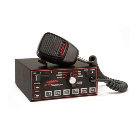
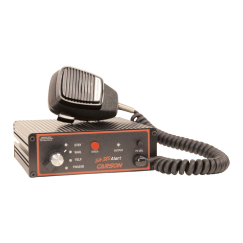
Page 4SA-400 Installation and Operating Instructions
9/6/01 CP4825A
INSTALLATION
Proper installation of the unit is essential for years of safe, reliable operation. Please
read all instruction before installing the unit. Failure to follow these instructions can
cause serious damage to the unit or vehicle and may void warranties.
SAFETY PRECAUTIONS
For the safety of the installer, vehicle operator, passengers and the community please
observe the following safety precautions. Failure to follow all safety precautions
and instructions may result in property damage, injury or death.
Qualifications -The installer must have a firm knowledge of basic electricity, vehicle
electrical systems and emergency equipment.
Sound Hazards -Sound levels produced by attached speakers can cause perma-
nent hearing loss. Never operate this unit without adequate hearing protection for
you and others in the area. (OSHA 1910.95)
Mounting -Mount the unit for easy access by the vehicle operator. DO NOT mount
in air bag deployment area. Assure clearances before drilling in vehicle. To prevent
internal damage mounting bolts must not enter case more than 1/4".
Wiring -Use wiring capable of handling the current required. Make sure all connec-
tions are tight. Route wiring to prevent wear, overheating and interference with air
bag deployment. Install and check all wiring before connection to vehicle battery.
Testing -Test all siren functions after installation to assure proper operation. Test
vehicle operation to assure no damage to vehicle.
Keep These Instructions -Keep these instructions in the vehicle or other safe place
for future reference. Advise the vehicle operator of the location.
UNPACKING
Inspect contents for shipping damage. If found alert carrier immediately. Contents
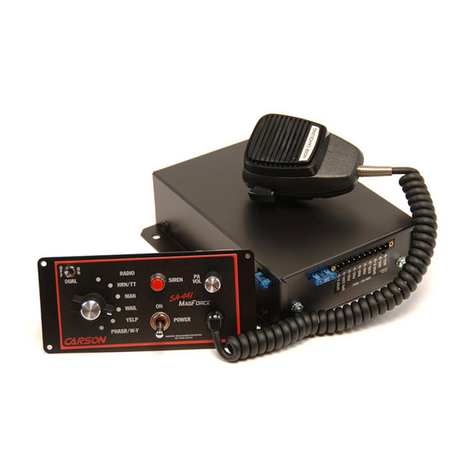
should include unit with attached microphone, wiring harness, mounting bracket, mi-
crophone bracket with 2 screws, 2 mounting bolts and these instructions. Contact
supplier immediately if any components are missing.
OPTION SWITCHES
Various options can be controlled by
turning on or off any of 5 DIP
switches internally mounted on the
right side of the PC board.
Cover Removal -The cover is held
in place by a snap-fastener on the
back of the unit. While holding the
case on the sides press hard with
your fingers on the back of the unit.
The chassis will slide out the front.
Two-Tone -Two-Tone can replace
Phaser by turning on the switch labeled "T-T".
Phaser Disable -The Phaser function can be completely disabled by turning on the
switch labeled "P_I".
Horn Disable -The Horn function can be disabled by turning on the switch labeled
“H_I”.
Horn Ring Cycler option (HRC) -This option allows selection of Wail, Yelp, Phaser
and Standby by repeatedly tapping the Siren button, horn ring or other switch con-
nected to the AUX input. It also provides Horn operation by pressing and holding the
switch or ring. Select this option by turning on the switch labeled “HRC”.
Short Manual -The Manual function can be set to immediately cut off when the Siren
button is released. This is selected by turning on the switch labeled “SM”.
OPTION SWITCHES
