Glensound Electronics GS-MPI004 User manual

GLENSOUND ELECTRONICS LTD
GS-MPI004 – GSM Beltpack Unit & GS-MPI005 – GSM Subrack Unit
DATE 25 03 08 ISSUE No. 2
HANDBOOK CONTENTS
DESCRIPTION PAGE No.
Panel Drawings & Block Diagram......................................................2
GS-MPI004 Front & Back............................................................ 2
GS-MPI004 Sides..........................................................................3
GS-MPI00 Front & Back............................................................ 4
Block Diagram..............................................................................
Principle of Operation.........................................................................6
Power Supply................................................................................ 6
Antenna......................................................................................... 6
Audio Interface..............................................................................6
Visual Interface............................................................................. 7
Memory Slots................................................................................ 7
SIM Card....................................................................................... 8
PIN Code....................................................................................... 8
Auto-Answer................................................................................. 8
Sounder..........................................................................................8
Operating Instructions.........................................................................9
Setup..............................................................................................9
Dialling..........................................................................................9
Enable / disable auto-answer.......................................................10
Store number in memory.............................................................10
Dial number from memory..........................................................10
Troubleshooting................................................................................ 11
Wiring Information........................................................................... 13
G GLENSOUND ELECTRONICS LTD.
6 BROOKS PLACE, MAIDSTONE, KENT, ME14 1HE, ENGLAND
www.glensound.co.uk email: [email protected]
Tel: +44 (0) 1622 7 3020
+44 (0) 1622 7 3662
Fax: +44 (0) 1622 762330

PANEL DRAWINGS & BLOCK DIAGRAM
GS-MPI004 FRONT & BACK
2

GS-MPI004 SIDES
3

GS-MPI005 FRONT & BACK
4

BLOCK DIAGRAM

PRINCIPLE OF OPERATION
The GS-MPI004 is a portable (belt-pack) quad-band GSM mobile phone unit, with
Mic and Line inputs, and a Line output. The GS-MPI00 is a 1U sub-rack unit,
designed for use in a 19" sub-rack, and contains three functionally separate GSM
mobile phone units, each equivalent to one GS-MPI004 unit.
POWER SUPPLY
The GS-MPI004 can be powered from either an external DC supply (9 – 12V), or
from 4 x AA batteries. The use of Lithium Manganese Dioxide batteries will yield
longer talk times than standard Alkaline batteries. If both an external DC supply
and batteries are connected, the external DC supply will take precedent. Note that
the external DC supply cannot be used to charge the batteries.
A “LOW BATT” LED is fitted onto the front panel of the GS-MPI004. This LED
will remain off while the battery voltage is above 1.1V per cell. Between 1.1V and
0.92V per cell, the LED will flash with increasing regularity, indicating an
increased urgency to replace the battery. Below 0.92V per cell, the LED will
remain on permanently, indicating that the unit is no longer operational due to low
voltage.
The GS-MPI00 , being a sub-rack unit, is powered by a 100 – 240V a.c. mains
supply. The single mains supply is used to power all three GSM mobile phones
inside the unit. Neither the battery box nor the “LOW BATT” LED are fitted.
ANTENNA
Both the GS-MPI004 and GS-MPI00 use SMA Bulkhead female connectors,
requiring an antenna with an SMA Bulkhead male connector. One antenna is
required per GSM mobile phone unit. The GS-MPI004 contains one mobile
phone, and therefore requires one antenna. The GS-MPI00 contains three mobile
phone units, and therefore requires up to three antennae for full operation.
AUDIO INTERFACE
The GS-MPI004 has separate balanced Mic and Line XLR inputs, which are mixed
together internally. Each mobile phone in the GS-MPI00 has a Line input, but no
Mic input. The input signal is adjusted by an input gain preset on the front panel,
before being passed through a compressor to the GSM interface. Phantom power
is not available on the Mic input of the GS-MPI004. Therefore, only dynamic
microphones can be used.
The audio output from the GSM interface is split between the Line output and the
headphones output. The Line output is adjusted by an output gain preset on the
front panel. The headphones output is mixed with a feed from the input (to provide
sidetone) and adjusted by the “HP VOLUME” knob on the front panel, before
being output on a ¼" Jack socket. On the GS-MPI004, this Jack socket is located
GS-MPI004 / Manual – Issue 2 6

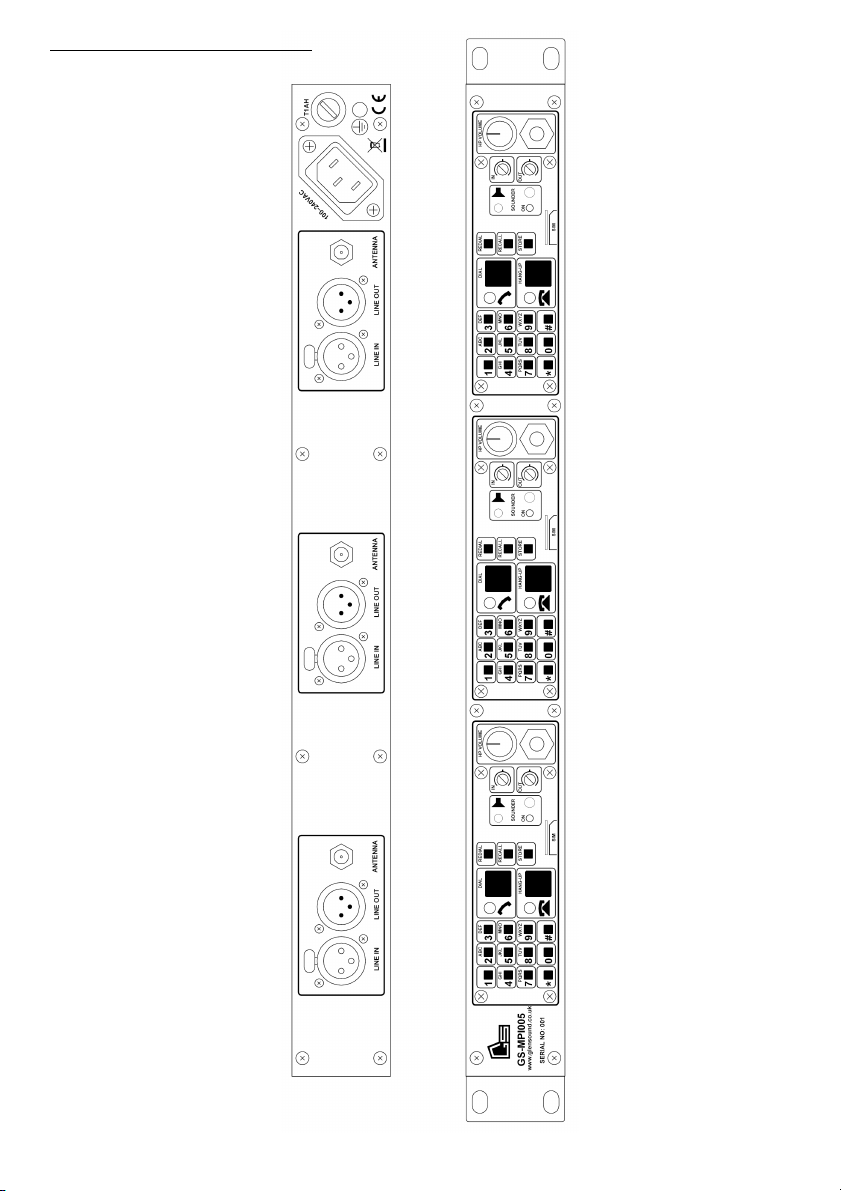
on the right-hand side panel. On the GS-MPI00 mobile phones, it is located on the
front panel. The headphones output is designed to drive high impedance
headphones. Use of other types of headphones will significantly reduce battery life.
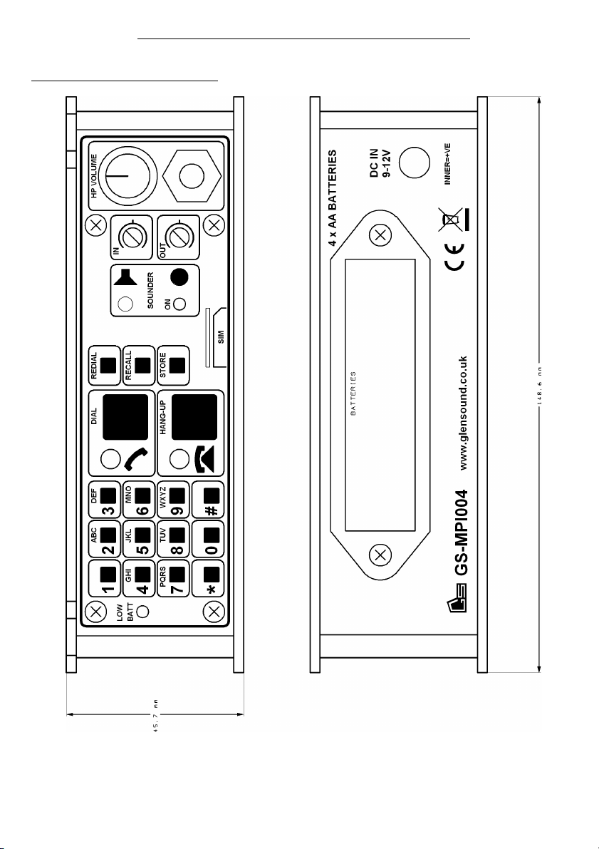
VISUAL INTERFACE
Each mobile phone unit has a standard 4x3 keypad, a large green “DIAL” push-
button and corresponding “OFF-HOOK” LED, and a large red “HANG-UP”
push-button and corresponding “ON-HOOK” LED. The DIAL push-button is
used to dial a phone number entered on the keypad, or to answer an incoming call.
The HANG-UP push-button is used to end a call, reject an incoming call, or to
clear a number that has been entered incorrectly.
When the unit is turned on, it will check if the PIN code is enabled. If it is, the
phone will quickly flash the “SOUNDER” LED four times, every three seconds.
This prompts the user to input the four digit PIN code in order to unlock the phone.
When the PIN code has been successfully entered, or if no PIN code was set on the
SIM card, the red ON-HOOK LED will flash, indicating that the unit is attempting
to register with a GSM network. Once registration is complete, the ON-HOOK
LED will be on solid and the OFF-HOOK LED will be off. This is the phone's idle
state, indicating that it is on-hook, and ready to dial or receive calls.
When a phone number is entered on the keypad and the DIAL push-button is
pressed, the ON-HOOK LED will be turned off and the OFF-HOOK LED will
start to flash, indicating that the phone is off-hook, and waiting for the phone at the
other end to start ringing. When this happens, the sounder will play a slow ringing
cadence, and the OFF-HOOK LED will flash in-time with the cadence. When the
remote phone is picked up, the OFF-HOOK LED will be turned on solid,
indicating that a call is in progress.
When an incoming call is received and the phone is on-hook, the ON-HOOK LED
will remain on, the sounder will play a fast ringing cadence, and the OFF-HOOK
LED will flash in-time with the cadence.
If a keypad button is pressed during a call, the phone will generate the
corresponding DTMF tone.
MEMORY SLOTS
Each mobile phone unit has nine numbered memory slots, plus one redial memory
slot. These are accessed using three yellow buttons: “REDIAL”, “RECALL” and
“STORE”. These three buttons can only be used when the phone is on-hook.
Pressing the REDIAL button will cause the phone to go off-hook and dial the last
number dialled. To store a number in a memory slot, type the number on the
keypad and press the STORE button, then press a button between 1 – 9 to select a
memory slot. The OFF-HOOK LED will quickly flash twice, indicating that the
number was successfully stored. To dial a number stored in memory, press the
RECALL button, then press a button between 1 – 9 to select a memory slot. The
GS-MPI004 / Manual – Issue 2 7

phone will go off-hook and dial the number. If no valid phone number is stored in
the selected memory slot, the sounder will give an indication of input error.
Note that the phone book stored on the SIM card is not accessible.
SIM CARD
Each mobile phone unit requires a separate SIM card. The SIM card must be
inserted u side down into the horizontal slot on the front panel, with the mitred
corner facing forwards, and the gold-plated contacts facing upwards. The SIM
card should be pressed in using a finger nail until it latches.. It can be removed by
pressing with the finger nail until it unlatches.
Note that the phone book stored on the SIM card is not accessible.
PIN CODE
When the mobile phone unit is turned on, it will check whether the PIN code on
the SIM card is enabled or not, and will prompt the user accordingly (as described
in the “Visual Int rfac ” section, above. The mobile phone cannot be used to
activate, deactivate, or change the SIM PIN. These actions should be performed by
placing the SIM card in a standard mobile phone.
AUTO-ANSWER
By default, the mobile phone will not attempt to automatically answer an incoming
call. However, each mobile phone can be separately configured to automatically
answer after 1 – 9 rings. To achieve this, hold down the appropriate keypad button
(0 – 9) while powering on the unit. This will configure the phone to auto-answer at
the beginning of the nth ring, where n is the number of the keypad button held
down. If n is 0, auto-answering will be disabled. The auto-answer setting is
stored, and recalled when the power is next turned on.
Note that many GSM networks activate a remote answering service after a fixed
number of rings. The auto-answer setting is unable to affect this, however the
GSM network provider may disable the remote answering service on request.
SOUNDER
Each mobile phone unit has a simplistic sounder, which provides ringing cadences
and indication of input error. The sounder can be toggled on and off using a push-
button on the front of the panel. The on/off state of the sounder is stored, and
recalled when the power is next turned on.
GS-MPI004 / Manual – Issue 2 8

OPERATING INSTRUCTIONS
SETUP
To setup the GS-MPI004 beltpack unit ready for use:
1. Screw suitable antenna onto SMA Bulkhead antenna connector.
2. Insert SIM card u side down into slot, following directions
given in the previous chapter.
3. Place 4xAA batteries into battery holder, and / or connect
external DC supply.
4. Turn unit on.
. If sounder LED starts flashing, type in SIM PIN code.
6. Wait for red ON-HOOK LED to stop flashing, indicating that the
GSM unit has successfully registered with the GSM network.
(GS-MPI004 unit is now r ady for us )
To setup the GS-MPI00 subrack unit ready for use:
1. Screw suitable antenna onto each SMA Bulkhead antenna
connector, as required.
2. Insert each SIM card u side down into slot, as required,
following directions given in the previous chapter.
3. Connect subrack unit to mains supply.
4. If any sounder LEDs start flashing, type in SIM PIN code.
. Wait for all red ON-HOOK LEDs to stop flashing, indicating
that each GSM unit has successfully registered with the GSM
network.
(GS-MPI005 unit is now r ady for us )
DIALLING
1. Type in phone number on keypad. Press the red “HANG-UP”
button and start again if the number was entered incorrectly.
2. Press the green “DIAL” button.
(ON-HOOK LED will turn off and OFF-HOOK LED will start to
flash, indicating that th phon is off-hook, and waiting for th
phon at th oth r nd to start ringing)
(Phon will r turn to on-hook condition if call fails. Oth rwis ,
wh n r mot phon starts ringing, th sound r will play a slow
ringing cad nc , and th OFF-HOOK LED will flash in-tim
with th cad nc )
(Wh n r mot phon is pick d up, OFF-HOOK LED will turn on
solid)
GS-MPI004 / Manual – Issue 2 9

ENABLE / DISABLE AUTO-ANSWER
1. Turn off mobile phone unit.
2. Hold down numeric key corresponding to the ring number that
auto-answering is desired on (0 for disable).
3. Turn on mobile phone unit, with numeric key still pressed.
4. Release key.
STORE NUMBER IN MEMORY
1. Type in phone number on keypad. Press the red “HANG-UP”
button and start again if the number was entered incorrectly.
2. Press the yellow “STORE” button.
3. Press a numeric key, between 1 – 9, indicating the memory slot
desired.
(OFF-HOOK LED will quickly flash twic , indicating that th
numb r was succ ssfully stor d)
DIAL NUMBER FROM MEMORY
1. Press the yellow “RECALL” button.
2. Press a numeric key, between 1 – 9, indicating the memory slot
desired.
(Th mobil phon will go off-hook and start dialling th phon
numb r)
GS-MPI004 / Manual – Issue 2 10

TROUBLESHOOTING
Problem Cause Solution
“BATT LOW” LED is flashing.
Battery voltage is low, but unit should
continue to operate correctly for the
moment. A shorter flash period denotes
a flatter battery.
Consider changing batteries, or connect
external DC supply.
“BATT LOW” LED is on solid. Battery voltage is sufficiently low that
the device will not operate correctly.
Change batteries, or connect external
DC supply.
GSM unit fails to register with network
(Red “ON-HOOK” LED and green
“OFF-HOOK” LED are both off,
“SOUNDER” LED is not flashing).
SIM card has not been inserted. Insert SIM card, then turn unit off and
on again.
“SOUNDER” LED starts flashing after
power-on. SIM PIN code is enabled on SIM card. Type in 4-digit SIM PIN code.
GSM unit fails to register with network
(Red “ON-HOOK” LED continues to
flash for more than a few seconds at
start-up), but “BATT LOW” LED is not
on or flashing.
2) Signal strength is too low.
3) Unsuitable GSM antenna is fitted.
4) Momentary glitch on GSM network.
Move unit within range of a mobile
phone mast.
Fit a suitable GSM antenna.
Turn unit off then on again.
GS-MPI004 / Manual – Issue 2 11

Problem Cause Solution
Red “ON-HOOK” LED starts to flash
after GSM registration is complete, or
when phone goes off-hook
1) Battery voltage is sufficiently low that
the device will not operate correctly, as
indicated by state of “BATT LOW”
LED.
2) Signal strength is too low.
3) Unsuitable GSM antenna is fitted.
Change batteries, or connect external
DC supply.
Move unit within range of a mobile
phone mast.
Fit a suitable GSM antenna.
Phone returns to on-hook state after
dialling.
1) Call failed (possibly invalid number,
remote phone line busy, call cancelled
by remote phone, etc.)
2) No credit left on SIM card.
Try again later.
Put SIM card into an ordinary mobile
phone and top-up credit.
Call fails when attempting to dial phone
number stored in memory slot.
Selected memory slot does not contain a
valid phone number.
Store a valid phone number in the slot,
or select another slot.
Incoming call appears to fail after fixed
number of rings.
GSM network is activating a remote
answering service.
Contact GSM network provider and
request remote answering service be
disabled.
Phantom-powered microphone does not
work when connected to device.
Phantom power is not available on this
device. Use a dynamic microphone instead.
GS-MPI004 / Manual – Issue 2 12

WIRING INFORMATION
Ty e Function
3-pin XLR Socket/Plug MIC IN / LINE IN / LINE OUT
Pin 1 = Ground
Pin 2 = In Phase
Pin 3 = Mate
6.3 mm Jack Socket HEADPHONES
Tip = In Phase
Ring = Mate
Sleeve = Ground
2. mm DC Plug External DC Power In (9 – 12V)
Centre = DC Positive
Sleeve = DC Negative
SMA Bulkhead Socket ANTENNA
Centre = RF Signal
Sleeve = Chassis
Note: The HEADPHONES output is designed to drive high
impedance headphones. The use of other types of
headphones will significantly reduce battery life.
GS-MPI004 / Manual – Issue 2 13
This manual suits for next models
1
Table of contents