Glentronics Basement Watchdog Special BWSP Operator's manual

Instruction Manual
& Safety Warnings
IMPORTANT: Even if you have the Basement Watchdog Special
Backup Sump Pump System installed by someone else, you must read
and follow the safety information contained in this manual. Failure
to do so could result in property damage, serious injury, or death.
Battery Backup
Sump Pump
System
Table of Contents
Important Safety Warnings and
Instructions
Electrical Precautions 1
Battery Preparation 1
Battery Precautions 1
Introduction
Items Included in System 2
Additional Items Needed 2
System Specifications 2
Replacement Parts List 2
Pump & Pipe
Installation Instructions
Installation Options 3
Direct Discharge to Outside 4
Hookup to Existing Discharge 5
Direct Discharge for Narrow Sumps 6
Hookup to Existing Discharge for
Narrow Sumps 7
Battery Instructions
Preparation of the Battery 8
Control Unit Hookup
Positioning the Float Switch 9
Hooking Up the Pump 9
Installing the Battery Fluid Sensor 9
Hooking Up the Battery 9
Hooking Up the Charger 9
Understanding the Warning
Lights and Alarms
Understanding the Automatic
Charging System 10
Silencing the Alarm
During an Emergency 10
Battery Alarm 10
Cleaning Battery Terminals 10,11
Replacing the Battery 11
Fuse Alarm 11
Water Alarm 12
Power Alarm 12
Pump Alarm 12
Replacing the Pump 12,13
Testing the System
Test-Reset-Silence Button 13
Testing the Float Switch 13
Parts & Service Information
Technical Support 13
Quick Reference Guide 14
Warranty 14

Important Safety
Warnings & Instructions
SAVE THESE INSTRUCTIONS. This manual
contains important SAFETY WARNINGS and
OPERATING INSTRUCTIONS for the Basement
Watchdog Special Battery Backup Sump Pump
System. You will need to refer to it before
attempting any installation or maintenance.
ALWAYS keep these instructions with the unit so
that they will be easily accessible.
Failure to read and follow these warnings and
instructions could result in property damage,
serious injury, or death. It is important to read
this manual, even if you did not install the
Basement Watchdog Special backup sump pump,
since this manual contains safety information
regarding the use and maintenance of this
product. DO NOT DISCARD THIS MANUAL.
ELECTRICAL PRECAUTIONS
Risk of electrical and fire hazard. May result
in death, serious injury, shock or burns.
To help reduce these risks, observe the
following precautions:
• DO NOT walk on wet areas of the basement
until all power has been turned off. If the
main power supply is in a wet basement, call
an electrician.
• NEVER handle the control unit with wet hands
or while standing on a wet surface.
• ALWAYS unplug the control unit and dis-
connect the cables from the battery before
attempting any maintenance or cleaning.
• ALWAYS unplug the main pump when instal-
ling or servicing the backup pump to avoid
electric shock.
• DO NOT expose the control unit to rain or
snow.
• Pull the plug rather than the cord when
disconnecting the control unit.
• An extension cord should not be used unless
absolutely necessary. If an extension cord
must be used, be sure the plug has the same
configuration as the plug on the control unit.
• Use of an attachment not recommended or
sold by the manufacturer may result in a risk
of fire or injury from an electrical shock.
• DO NOT operate the computer control unit if it
has received a sharp blow, been dropped, or
otherwise damaged in any way. Contact
Glentronics technical support at 800-991-
0466, option #3.
• DO NOT disassemble the control unit. When
service is required, contact Glentronics tech-
nical support at (800) 991-0466, option #3.
Return the control unit to the manufacturer for
any repairs at the following address:
Glentronics, Inc.
640 Heathrow Drive
Lincolnshire, IL 60069
BATTERY PREPARATION
Sulfuric acid can cause blindness or severe
burns. Avoid contact with skin, eyes or
clothing. In the event of accident, flush
with water and call a physician immediately.
KEEP OUT OF REACH OF CHILDREN.
To help reduce these risks, observe the
following precautions:
• Someone should be within range of your voice
or close enough to come to your aid when you
work near a lead-acid battery.
• Have plenty of fresh water and soap nearby in
case battery acid contacts skin, clothing or
eyes.
• Wear eye and clothing protection and avoid
touching your eyes while working with battery
acid or working near the battery.
• If battery acid contacts skin or clothing, wash
immediately with soap and water. If acid
enters eye, immediately flood eye with run-
ning cold water for at least 10 minutes and get
medical attention.
• Battery posts and terminals contain lead and
lead compounds, chemicals known to the State
of California to cause cancer and reproductive
harm. Wash hands after handling.
BATTERY PRECAUTIONS
Explosive gases could cause serious injury or
death. Cigarettes, flames or sparks could
cause battery to explode in enclosed spaces.
Charge in well-ventilated area. Always
shield eyes and face from battery. Keep vent
caps tight and level.
To help reduce these risks, observe the
following precautions:
• NEVER smoke or allow a spark or flame in the
vicinity of the battery.
• Use the Basement Watchdog Special control
unit for charging a LEAD-ACID battery only.
Do not use the control unit for charging dry-
cell batteries that are most commonly used
with home appliances.
• Be sure the area around the battery is well
ventilated.
• When cleaning or adding water to the battery,
first fan the top of the battery with a piece of
cardboard or another non-metallicmaterial to
blow away any hydrogen gas that may have
been emitted from the battery.
• DO NOT drop a metal tool onto the battery. It
might spark or short-circuit the battery and
cause an explosion.
• Remove personal metal items such as rings,
bracelets, watches, etc. when working with a
lead-acid battery. A short circuit through one
of these items can melt it causing a severe
burn.
• ALWAYS remove the charger from the electrical
outlet before connecting or disconnecting the
battery cables. Never allow the rings to touch
each other.
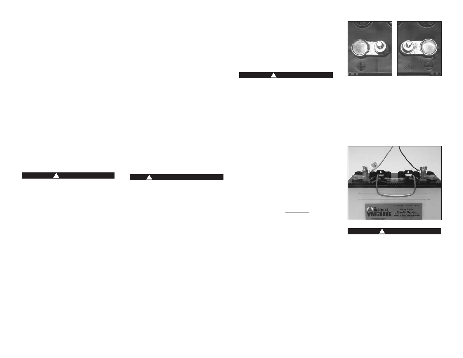
• Check the polarity of the battery posts. The
POSITIVE (+) battery post usually has a larger
diameter than the NEGATIVE (-) post.
• When connecting the battery cables, first
connect the small ring on the end of the
BLACK wire to the NEGATIVE (-) post of the
battery, and then connect the large ring on
end of the RED wire to the POSITIVE (+) post
of the battery.
Do not use system to pump flammable or
explosive fluids such as gasoline, fuel oil,
kerosene, etc.
Page 1
!DANGER
!DANGER
!WARNING / POISON
!DANGER
POSITIVE POST HAS
LARGER DIAMETER NEGATIVE POST HAS
SMALLER DIAMETER

Introduction
The Basement Watchdog Special backup sump
pump system is battery-operated. It is designed
as an emergency backup system to support your
regular AC sump pump, and it will automatically
begin pumping anytime the float switch is
activated. Should any malfunction or emergency
occur that involves the sump pump, the battery,
or the AC power, your Basement Watchdog
Special system will sound an alarm. A light on
the display panel of the control unit will indicate
the cause of the alarm and the corrective action.
The Basement Watchdog Special
Sump Pump System includes:
A control unit with a float switch and a
battery fluid level sensor
A pump with 11⁄2” PVC pipe adapter
A plastic wire tie for mounting the float
switch
A battery box
A battery cap with a hole to accommodate
the fluid sensor
A battery charger
You will also need to supply:
A Basement Watchdog 7.5 Hour Standby
Battery, or another deep cycle battery
(Do not use a maintenance-free or a sealed
battery.)
11⁄2” rigid PVC pipe and fittings
PVC cement and primer
A rubber union with hose clamps or a “Y”
connector and two (2) check valves
depending on the installation method
you use
Six (6) quarts of 1.265 specific gravity
battery acid
For narrow sump pits you will need some
additional parts:
An “L” bracket at least 6 inches long.
(Preferably one that will not rust.)
Two (2) stainless steel hose clamps
One (1) stainless steel screw (#8-32 x 3/4”),
a matching washer & nut
System Specifications
Power supply requirements . . . . . . 115 volts AC
Pumping capacity . . . . . . . . . . 2500 GPH @ 0’
Pumping capacity . . . . . . . . . 1730 GPH @ 10’
Pump dimensions . . . . . . . . . . 75⁄8H x 53⁄16” W
Pump dimensions w/elbow. . . . . . 75⁄8H x 9” W
Pump housing & strainer . . . . . .Non-corrosive,
will not rust
Pump . . . . . . . . . . . . . . . . . . . .Can run dry;
can be used in sumps with
water softener or laundry discharge
Float switch . . . . . . . . . .Independent; can be
set at any level
Replacement Parts List
Description Part No.
Pump 1011002
Float switch assembly 1020003
Fluid sensor assembly 1014001
Pipe Adapter 1120002
Charger 1015001
Battery Box 1113003
Corrosion protector 1305000
Battery cap with hole 1125000
Call 800-991-0466 to order parts.
Page 2
Battery
Wires
Control Unit
Battery
Box
Charger
Cap
Wire Tie
Float
Switch
Pipe
Adapter
Pump
Fluid Sensor

Pump & Pipe
Installation Instructions
There are two basic methods that can be used to
install the pump, a direct discharge to the
outside of the building, or a hookup to an
existing discharge pipe. The same two options
apply in very narrow sump pits where the backup
pump must be mounted above the main pump.
Whenever possible, install your Basement
Watchdog Special backup pump with a direct
discharge to the outdoors. By using this
method, there will always be an outlet for the
water from the sump. During times of very heavy
rain, many storm sewers fill up. If your pump is
trying to discharge water into a full sewer, there
is nowhere for the water to go. By discharging
directly outdoors, there is always an outlet for
the water that is pumped out of the sump. For
this method, you will need to drill a hole through
a floor joist or the foundation from the basement
to the outside of the house.
If the direct discharge method is not possible or
convenient, the Basement Watchdog pump can
be hooked up to the same line as your AC sump
pump by installing a “Y” connector and two
check valves.
In most cases the backup pump will fit next to
the main AC pump in the sump pit. In very
narrow pits, the backup pump can be mounted
above the main pump. Try to fit the backup
pump on the floor of the sump first.
Select the installation method that will best suit
your needs from the diagrams at the right. Full
instructions for each installation method are
provided on the following pages.
Installation will take a couple hours.
Page 3
NORMAL SUMP PIT
INSTALLATIONS
PUMP
WIRE
PIPE
ADAPTER
BASEMENT WATCHDOG
PUMP
FLOOR
JOIST
MAIN
AC PUMP
RIGID
1-1/2"
PVC PIPE
CHECK
VALVE
DRAIN TILE
1/8" HOLE
45°ELBOW
"Y" CONNECTOR
CHECK
VALVE
PUMP
WIRE
HOSE CLAMPS
PIPE ADAPTER
BASEMENT WATCHDOG
PUMP
"L" BRACKET
FLOOR
JOIST
MAIN AC PUMP
RIGID
1-1/2"
PVC PIPE
CHECK
VALVE
RIGID
1-1/2"
PVC PIPE
DRAIN TILE
45°ELBOW
"Y"
CONNECTOR
CHECK
VALVE
1/8" HOLE
PUMP
WIRE
PIPE ADAPTER
DRILL 1/8" HOLE
IF CHECK
VALVE USED
BASEMENT WATCHDOG
PUMP
FLOOR
JOIST
MAIN
AC PUMP
SLOPE
PIPE
DOWN
RIGID
1-1/2"
PVC PIPE
RUBBER
UNION
OR CHECK
VALVE
CHECK
VALVE
DRAIN TILE
PUMP
WIRE
CHECK
VALVE
HOSE
CLAMPS
"L" BRACKET
FLOOR
JOIST
MAIN
AC PUMP
SLOPE
PIPE
DOWN
RIGID
1-1/2"
PVC PIPE
RUBBER
UNION
OR CHECK
VALVE
DRAIN TILE
PIPE ADAPTER
DRILL 1/8" HOLE
IF CHECK
VALVE USED
BASEMENT WATCHDOG
PUMP
Installation B
Hookup to
Existing
Discharge Pipe
Page 6
Installation C
Direct Discharge
to Outside
Page 7
Installation D
Hookup to
Existing
Discharge Pipe
Page 8
Installation A
Direct Discharge
to Outside
Page 5
NARROW SUMP PIT
INSTALLATIONS

Page 4
Pump & Pipe
Installation Instructions
INSTALLATION A:
DIRECT DISCHARGE TO THE OUTSIDE OF THE
BUILDING (Diagram A)
sDANGER
Unplug the main AC pump when installing
the backup pump to avoid electric shock.
Failure to do so could cause serious injury
or death.
1. Cut a four-foot (4’) piece of 11⁄2” rigid PVC
pipe and cement it to the pipe adapter that
is attached to the elbow on the pump.
2. Secure the pump wire so that the plug on the
end will not fall into the sump. Attach the
wire to the pipe with a piece of tape.
3. Place the pump with the 4’ PVC pipe
attachment on the bottom of the sump floor
next to the main AC pump. Do not mount
the pump to any existing pipes; it should be
placed on the floor of the sump. A brick may
be placed under the pump if there are rocks
or other debris on the sump floor that may
clog the pump.
4. Attach a rubber union or check valve (sold
separately) to the top of the 11⁄2” pipe. This
will allow the pump to be removed easily,
should the need arise.
The path of the rest of the pipe and the details
of each installation will vary. Using sound
plumbing practices, try to route the discharge
pipe to an exterior wall via the shortest path
with the fewest turns. More turns will reduce
the pumping capacity. The pipe section exiting
the building should be on a downward slope so
that the water in the pipe will exit outside
instead of returning to the sump. Extend the
discharge pipe outside the building as far as
possible to avoid the return of discharged water
to the sump. Be sure to seal the hole in the wall
where the pipe exits and cement or clamp all
connections securely to prevent leaking. No
check valve is needed with this method of
installation, as long as you use less than 20
feet of pipe.
CAUTION
If you use more than a total of 20 feet of pipe
in the installation, install a check valve in
place of the rubber union. Make sure it is
installed with the arrow pointing up or it will
not prevent the backflow of water. When a
check valve is used, a 1/8” hole must be drilled
in the PVC pipe 3” above the Basement
Watchdog pump. If a hole is not drilled above
the pump, an air lock may prevent the pump
from operating, and the basement will flood.
PUMP
WIRE
PIPE ADAPTER
DRILL 1/8" HOLE
IF CHECK
VALVE USED
BASEMENT WATCHDOG
PUMP
FLOOR
JOIST
MAIN
AC PUMP
SLOPE
PIPE
DOWN
RIGID
1-1/2"
PVC PIPE
RUBBER
UNION
OR CHECK
VALVE
CHECK
VALVE
DRAIN TILE
1
2
3
4
Diagram A
!DANGER
CAUTION

Page 5
Pump & Pipe
Installation Instructions
INSTALLATION B:
HOOKUP TO AN EXISTING DISCHARGE PIPE
(Diagram B)
sDANGER
Unplug the main AC pump when installing the
backup pump to avoid electric shock. Failure
to do so could cause serious injury or death.
1. Cut a four-foot (4’) piece of 11⁄2” rigid PVC
pipe and cement it to the pipe adapter that is
attached to the elbow on the pump.
2. (a) Install a check valve on the PVC pipe
attached to the Basement Watchdog pump.
Make sure it is installed with the arrow
pointing up or it will not prevent the backflow
of water.
2. (b) When a check valve is used, drill a 1/8”
hole in the 11⁄2” PVC pipe three inches (3”)
above the connection to the Basement
Watchdog pump. Drill the hole at a 45º angle
toward the bottom of the sump to avoid
splashing water outside the sump pit. If a
1/8” hole is not drilled above the pump, an
air lock may prevent the pump from
operating, and the basement will flood.
3. If there is no check valve on the main AC
pump, one must be installed at this time.
Then install a “Y” connector above the check
valve on the discharge pipe for the main AC
pump.
4. Secure the pump wire so that the plug on the
end will not fall into the sump. Attach the
wire to the pipe with a piece of tape.
5. Place the pump with the 4’ PVC pipe
attachment on the bottom of the sump floor,
next to the main AC pump. Do not mount the
pump to any existing pipes...it should be
placed on the floor of the sump. A brick may
be placed under the pump if there are rocks or
other debris on the sump floor.
6. Connect a 11⁄2” diameter discharge pipe above
the check valve of the Basement Watchdog
pump, and attach a 45º elbow to that pipe.
Extend another piece of pipe to reach the “Y”
connector you have inserted above the check
valve on the discharge pipe of the main
pump.
7. Cement or clamp all connections securely to
prevent leaking.
PUMP
WIRE
PIPE
ADAPTER
BASEMENT WATCHDOG
PUMP
FLOOR
JOIST
MAIN
AC PUMP
RIGID
1-1/2"
PVC PIPE
CHECK
VALVE
DRAIN TILE
1/8" HOLE
45°ELBOW
"Y" CONNECTOR
CHECK
VALVE
Diagram B
34
56
2a 2b
CAUTION
!DANGER
1

Page 6
Pump & Pipe
Installation Instructions
INSTALLATION C:
DIRECT DISCHARGE TO THE OUTSIDE OF THE
BUILDING FOR NARROW SUMP PITS
(Diagram C)
sDANGER
Unplug the main AC pump when installing
the backup pump to avoid electric shock.
Failure to do so could cause serious injury
or death.
1. Attach an “L” bracket to the discharge pipe of
the main AC pump with two (2) stainless
steel hose clamps. Position the bracket so
the bottom of the “L” is just above the top of
the main pump, and out of the way of any
float switch on the main pump.
2. (a) Remove the black bottom strainer of the
pump by pressing in the two tabs on the
strainer. There are holes suitable for
mounting on the bottom of the strainer. (b)
Using a #8-32 x 3/4” stainless screw, washer
& nut, attach the strainer to the “L” bracket.
(c) Once the strainer is attached, simply press
the pump body onto the mounted strainer.
3. Cut a three-foot (3’) piece of 11⁄2” rigid PVC
pipe and cement it to the pipe adapter that
is attached to the elbow on the pump.
4. Secure the pump wire so that the plug on the
end will not fall into the sump. Attach the
wire to the pipe with a piece of tape.
5. Attach a rubber union or check valve (sold
separately) to the top of the 11⁄2” pipe. This
will allow the pump to be removed easily,
should the need arise.
The path of the rest of the pipe and the details
of each installation will vary. Using sound
plumbing practices try to route the discharge
pipe to an exterior wall via the shortest path
with the fewest turns. More turns will reduce
the pumping capacity. The pipe section exiting
the building should be on a downward slope so
that the water in the pipe will exit outside
instead of returning to the sump. Extend the
discharge pipe outside the building as far as
possible to avoid the return of
discharged water to the sump. Be
sure to seal the hole in the wall
where the pipe exits and cement or
clamp all connections securely to
prevent leaking. No check valve is
needed with this method of
installation, as long as you use less
than 20 feet of pipe.
PUMP
WIRE
CHECK
VALVE
HOSE
CLAMPS
"L" BRACKET
FLOOR
JOIST
MAIN
AC PUMP
SLOPE
PIPE
DOWN
RIGID
1-1/2"
PVC PIPE
RUBBER
UNION
OR CHECK
VALVE
DRAIN TILE
PIPE ADAPTER
DRILL 1/8" HOLE
IF CHECK
VALVE USED
BASEMENT WATCHDOG
PUMP
Diagram C
2c 4
5
3
CAUTION
!DANGER
12b2a
“L” BRACKET
If you use more than a total of 20 feet of pipe in the
installation, install a check valve in place of the
rubber union. Make sure it is installed with the arrow
pointing up or it will not prevent the backflow of
water. When a check valve is used, a 1/8” hole must
be drilled in the PVC pipe 3” above the Basement
Watchdog pump. If a hole is not drilled above the
pump an air lock may prevent the pump from
operating, and the basement
will flood.

Page 7
Pump & Pipe
Installation Instructions
INSTALLATION D:
HOOKUP TO EXISTING DISCHARGE PIPE
FOR NARROW SUMP PITS
(Diagram D)
sDANGER
Unplug the main AC pump when installing the
backup pump to avoid electric shock. Failure
to do so could cause serious injury or death.
1. Attach the “L” bracket to the discharge pipe
of the main AC pump with two (2) stainless
steel hose clamps. Position the bracket so the
bottom of the “L” is just above the top of the
main pump, and out of the way of any float
switch on the main pump.
2.(a) Remove the black bottom strainer of the
pump by pressing in the two tabs on the
strainer. There are holes suitable for
mounting on the bottom of the strainer. (b)
Using a #8-32 x 3/4” stainless screw, washer
and nut, attach the strainer to the “L”
bracket. (c) Once the strainer is attached,
simply press the pump body onto the
mounted strainer.
3. Cut a three-foot (3’) piece of 11⁄2” rigid PVC
pipe and cement it to the pipe adapter that is
attached to the elbow on the pump.
4. (a) Install a check valve on the PVC pipe
attached to the Basement Watchdog pump.
Make sure it is installed with the arrow
pointing up or it will not prevent the backflow
of water.
4. (b) When a check valve is used, drill a 1/8”
hole in the 11⁄2” PVC pipe three inches (3”)
above the connection to the Basement
Watchdog pump. Drill the hole at a 45º angle
toward the bottom of the sump to avoid
splashing water outside the sump pit. If a hole
is not drilled above the pump, an air lock may
prevent the pump from operating, and the
basement will flood.
5. If there is no check valve on the main AC
pump, one must be installed at this time.
Then install a “Y” connector above the check
valve on the discharge pipe for the main AC
pump.
6. Secure the pump wire so that the plug on the
end will not fall into the sump. Attach the
wire to the pipe with tape.
7. Connect a 11⁄2” diameter discharge pipe above
the check valve of the Basement Watchdog
pump, and attach a 45º elbow to that pipe.
Extend another piece of pipe to reach the “Y”
connector you have inserted above the check
valve on the discharge pipe of the main
pump.
8. Cement or clamp all connections securely to
prevent leaking.
PUMP
WIRE
HOSE CLAMPS
PIPE ADAPTER
BASEMENT WATCHDOG
PUMP
"L" BRACKET
FLOOR
JOIST
MAIN AC PUMP
RIGID
1-1/2"
PVC PIPE
CHECK
VALVE
RIGID
1-1/2"
PVC PIPE
DRAIN TILE
45°ELBOW
"Y"
CONNECTOR
CHECK
VALVE
1/8" HOLE
3
5
1
67
4a 4b
2a
2b 2c
Diagram D
“L”
BRACKET
CAUTION
!DANGER

Page 8
Battery Instructions
A new Basement Watchdog 7.5 Hour Standby
Battery will run this system for a minimum of 7.5
hours continuously. However, most of the time the
pump will turn on and off, and the battery will run
the pump intermittently for days. In addition, the
unique materials in the battery enable it to last for
five to seven years in standby service.
• The use of automotive batteries is NOT recom-
mended. Automotive batteries are not designed
for this application. They will only run the pump
for a short time and will have a shorter life than
a standby battery.
• DO NOT use a maintenance-free or a sealed
battery. They are made of different materials and
will trigger a false “Battery problem” alarm.
• The battery fluid sensor and cap are designed to
fit the Basement Watchdog batteries.Measuring
the battery fluid is one of the most important
features of the system; since about 80% of
backup sump pump failures are the result of a
dead battery.
Do not use the enclosed battery cap on any
battery except a Basement Watchdog battery.
Do not drill a hole in the cap of another brand
of battery to accommodate the fluid sensor.
Batteries emit explosive gases, which can
cause serious injury or death.
PREPARING THE BASEMENT WATCHDOG
STANDBY BATTERY
The Basement Watchdog batteries are shipped dry
(without acid) so they never lose power before you
take them home. A battery is activated when the
acid is added, and then it slowly begins to
deteriorate as it ages. By adding the acid just
before use, the battery will always be fresh. Use
1.265 specific gravity battery acid to fill the
battery. It is available where you purchased the
battery.
Wear eye and clothing protection. If battery
acid contacts skin or clothing, wash
immediately with soap and water. If acid
enters eyes, flush with water for 10 minutes
and get medical attention. Review the safety
instructions on page 1.
1. Remove the battery box top by pushing in the
tabs on the front and back of the box and
lifting up.
2. Place the battery box on the floor. Place the dry
(unfilled) battery into the battery box. Remove
the foil seal on the top of the battery.
3.(a) Carefully push in the perforated tab at the
top of the acid pack. Lift up the large tab and
pull out the dispensing hose. Hold the hose
upright above the pack and squeeze the hose
forcing all the acid back into the pack. (b)
Position the acid pack and battery as shown at
the right. Remove the caps from the battery.
Pinch the end of the hose together and cut off
the tip. Insert the end of the hose into each
cell. Control the flow by pinching the hose with
thumb and forefinger. Fill each cell of the
battery to a level just covering the battery
plates, and then go back and top off each cell
equally. It is important to have the cells filled
equally or the battery will not operate
properly. The acid should reach a level just
below the cap ring. (Diagram E)
A newly filled battery will sometimes require
additional acid after about ten minutes. Re-
examine the fill level and add additional acid, if
necessary. The battery acid may bubble at this
time and give off a sulfur-like smell, but this is
normal. After the battery has been filled, screw
the caps on the top of the battery.
CAUTION
When you fill the battery for the FIRST time, it will
be the ONLY time you add acid to the battery. In
the future, when the fluid level is low, add distilled
water to the cells. Never add more acid.
Do not throw an old battery in the
trash. Take it to a service station or
recycling center.
2nd LEVEL
1st LEVEL
PLATES
CELL WALL
1. FILL TO 1st LEVEL, COVER THE PLATES
2. THEN FILL TO 2nd LEVEL, JUST BELOW
THE BOTTOM OF THE CAP RINGS
BATTERY TERMINALS
BATTERY CAP RINGS
CROSS SECTION OF BATTERY
Diagram E
12
3a 3b
CAUTION
!DANGER
!DANGER
CAUTION

Page 9
Control Unit Hookup
Risk of electrical shock or battery explosion,
which can cause serious injury or death.
Unplug the main AC pump to avoid electrical
shock. Wear eye protection. Work in a well-
ventilated area. Do not smoke or allow a
spark or flame in the vicinity of the battery.
Avoid dropping metal tools on the battery.
If battery acid contacts eyes, flush with
water for 10 minutes. Review the safety
instructions on page 1.
When you position the control unit, be sure the
charger cord will reach the AC power outlet and
the pump cable and the float switch will reach
the bottom of the sump. Position the unit in a
well-ventilated area. (Diagram F)
1. Positioning the float switch: The float
switch will turn on the pump when the water
rises to the top of the switch, and it will
remain running as long as the water is above
the float switch. When the water drops below
the float switch, an internal timer in the
control unit will keep the pump running an
additional 25 seconds to empty the sump pit.
The switch should be mounted about six
inches (6”) above the water level line in the
sump pit. (a) Attach the float switch very
securely to the discharge pipe with the plastic
wire tie. (b) If the pump is stacked above the
main AC pump in a narrow sump pit, the float
may be attached to the elbow of the pump.
Be sure the switch is positioned vertically with
the mounting bracket at the top. Do not tilt
the switch. Do not position the float switch on
the side of the discharge pipe facing the drain
tile or any incoming rush of water!
2. Hooking up the pump: Remove the security
tag from the pump and plug the pump wires
into the pump connector on the back of the
control unit.
3. Installing the battery fluid sensor: Remove
the cover of the battery box by pushing in the
tabs on the front and back, then lifting up.
Fan the area around the top of the battery
with a piece of cardboard (or another non-
metallicmaterial) to remove any hydrogen
gas that may have been emitted from the
battery. Replace the battery cap that is 2nd
from the POSITIVE (+) post of the battery with
the yellow battery cap that is provided in the
Basement Watchdog Special package. An arrow on
the top of the battery marks this position. There
are two holes in the battery cap. Insert the fluid
sensor in the hole that is off-center on the top of
the cap. Do not glue the sensor into the cap.
CAUTION
If you are not using the Basement Watchdog
battery, you cannot use the battery fluid sensor.
However you must attach the sensor to the
POSITIVE (+) post of the battery or the alarm
will sound continuously. The Basement Watchdog
Special Sump Pump System will not warn you if
the fluid level is
low in this
configuration. You
will need to check
your battery every
couple of months
to see if it needs
water. If the
battery dries out,
the system will not
work.
4. Hooking up the battery: Remove the wing
nuts from the battery terminals. Remove the
security tag from the battery cables. Attach
the battery cables to the battery...the BLACK
wire to the NEGATIVE (-) post, and then the
RED wire to the POSITIVE (+) post. Replace
the wing nuts and tighten.
5. Hooking up the charger: Immediately plug
the charger into the charger hole on the back
of the control unit, then into an AC outlet on
the wall. (You can provide additional
protection for the control unit by using a
surge protector.)
6. Secure the cover on the battery box by
slipping the tabs through the fittings on the
front and back of the box. BE SURE TO PLUG
IN THE MAIN AC PUMP.
CHARGER
BATTERY
BOX
PUMP
WIRE
DRAIN TILE
MAIN AC PUMP
FLOAT WIRE
FLOAT SWITCH
PIPE ADAPTER
BASEMENT WATCHDOG
PUMP
WIRE
TIE
WATER
LEVEL LINE
BLACK
BATTERY
CABLE
BATTERY
TERMINAL
WALL OUTLET
RED
BATTERY
CABLE
SENSOR
CONTROL
UNIT
Diagram F
!DANGER
1b
35
4
2
FUSE
CHARGER
FUSE
CHARGER
1a
PUMP
CHARGER
PUMP

Page 10
Understanding the
Warnings & Alarms
The Basement Watchdog Special control unit
features a series of warning lights that pinpoint
potential problems. In addition, an alarm
sounds to alert you to the problem. In some
cases, the lights and alarm will go off
automatically when the problem has been
solved. In others, the YELLOW button must be
pushed to silence the alarm. Refer to the table
below for a quick review of the features and their
corresponding alarm status.
UNDERSTANDING THE
AUTOMATIC CHARGING SYSTEM
The Basement Watchdog Special is equipped
with a computer-controlled automatic charging
system. The computer is constantly monitoring
the battery and will supply a pre-programmed
amount of energy to keep your battery at full
charge. The CHARGING light will be on while the
battery is charging, and off when it is not
charging. The normal charge cycle is in one-
hour increments, which increases the life of the
battery and reduces the amount of water loss. If
the battery is discharged from extended use, the
charger will remain on until the battery is
completely recharged.
SILENCING THE ALARM
DURING AN EMERGENCY
The Basement Watchdog Special allows you to
silence the alarm during an emergency, however
the warning light will remain on until the
problem is corrected.
• Press the YELLOW button for 1 second to reset
the pump alarm, and silence the other alarms
for 2 minutes.
• Press the YELLOW button for 5 seconds to
silence the alarms for 24 hours. A brief
buzzing sound will notify you that the alarms
have been silenced. The alarms will
automatically reactivate in 24 hours if the
warning conditions still exist.
BATTERY ALARM
This light and alarm will go on when the control
unit senses that the battery has approximately
1/2 hour of continuous pumping energy left.
This could occur when:
• The pump has been running for many hours
and is reaching the last half-hour of operating
power.
• The battery is getting old and should be
replaced.
• Corrosion on battery terminals and/or cable
rings is preventing the battery from charging
properly.
Check the battery cables and the battery terminals
for corrosion. Clean and tighten them as needed.
The procedure is described at the right.
If the battery alarm goes on while the pump is
running and the power is out, you will have a
minimum of 1/2 hour of pumping time to replace
the battery. (In most cases, the pump does not
run continuously, and therefore, you actually
have longer.) You will not be able to silence the
alarm. Left unattended, the basement will flood.
In a severe emergency, if a replacement battery
is not available, you could temporarily use your
car battery.
Once the AC power is restored, the battery will
recharge automatically, unless it is old or
damaged. The alarm will remain on until the
YELLOW button is pressed for 1 second.
In the event that your Basement Watchdog sump
pump system has pumped for an extended period
of time, the battery can become very depleted.
In this condition, when the AC power is returned
to the unit, a battery alarm will continue to
sound. The battery may need a longer period to
recharge.
For a fast recharge, an automotive or marine
battery charger can be used to recharge the
battery. Follow the manufacturers instructions
and safety information included with the charger.
CAUTION
When another charger is used, first disconnect
the Basement Watchdog charger from the control
unit, and then disconnect the control unit from
the battery. Charging without disconnecting the
control unit will destroy the control unit and void
the warranty.
If the battery is relatively new and the battery
alarm is activated, before you replace the
battery, call the Glentronics service department
at 800-991-0466, option #3.
TO CLEAN THE BATTERY TERMINALS
AND CABLES
Risk of electrical shock or battery explosion,
which can cause serious injury or death.
Wear eye protection. Work in a well-
ventilated area. Do not smoke or allow a
spark or flame in the vicinity of the battery.
Avoid dropping metal tools on the battery.
If battery acid contacts eyes, flush with
water for 10 minutes. Review the safety
instructions on page 1.
REFER TO THE PHOTOS ON PAGE 11.
1. Unplug the charger from the wall outlet.
2. Remove the cover of the battery box by
pushing in the tabs on the front and back,
then lifting up.
3. Fan the area around the top of the battery
with a piece of cardboard (or another non-
metallicmaterial) to remove any hydrogen gas
that may have been emitted from the battery.
4. Unscrew the wing nuts. Remove the battery
cables and clean the battery posts with a
battery post terminal cleaner or a wire brush.
5. Clean the corrosion off of the ring connectors
on the ends of the battery wires. Use a stiff
brush or sandpaper.
6. If the fluid sensor has come out of the battery
Warning
BATTERY
FUSE
WATER
PUMP
POWER
Alarm shuts off
automatically
when problem
is corrected
No, must push
"YELLOW"button
Yes
Yes
No, must push
"YELLOW" button
Yes, but light will
flash until "YELLOW"
button is pushed
FRONT PANEL OF CONTROL UNIT
!DANGER

Page 11
cap, replace it now. Then, replace the battery
cables, BLACK to the NEGATIVE (-) post, and
then RED to the POSITIVE (-) post. Tighten
the wing nuts.
7. Plug the charger into the wall outlet. (You
can provide additional protection for the
control unit by using a surge protector.)
REPLACING THE BATTERY
Risk of electrical shock or battery explosion,
which can cause serious injury or death.
Wear eye protection. Work in a well-
ventilated area. Do not smoke or allow a
spark or flame in the vicinity of the battery.
Avoid dropping metal tools on the battery.
If battery acid contacts eyes, flush with
water for 10 minutes. Review the safety
instructions on page 1.
REFER TO THE PHOTOS AT RIGHT.
1. Unplug the charger from the wall outlet.
2. Remove the cover of the battery box by
pushing in the tabs on the front and back,
then lifting up.
3. Fan the area around the top of the battery
with a piece of cardboard (or another non-
metallicmaterial) to remove any hydrogen gas
that may have been emitted from the battery.
4. Remove the fluid sensor from the battery cap,
and then remove the battery cap. Save it for
use in the new battery.
5. Unscrew the wing nuts and remove the battery
cables.
6. Fill the battery following the instructions on
page 8.
7. Replace the battery cables, BLACK to the
NEGATIVE (-) post, and then RED to the
POSITIVE (+) post.
8. Rinse and dry the YELLOW cap from the old
battery to remove any residue. Replace the
BLACK battery cap in the cell that is 2nd from
the POSITIVE post with the YELLOW cap from
the old battery. Insert the fluid sensor in the
cap. Put the BLACK battery cap on the old
battery.
9. Plug the charger into the wall outlet. (You
can provide additional protection for the
control unit by using a surge protector.)
FUSE ALARM
Unplug the main AC pump when installing the
backup pump to avoid electric shock. Failure
to do so could cause serious injury or death.
This alarm indicates that the 20-amp safety fuse
on the back of the control unit has blown. This
can be the result of a clogged pump motor, or
pump wires that have been shorted out. To
determine the problem:
REFER TO THE PHOTOS ON PAGE 12.
1. Unplug the AC pump from the wall outlet.
2. Unplug the Basement Watchdog pump from
the back of the control unit.
3. (a) Release the rubber union or check valve
and remove the pump from the sump pit.
(b) Remove the strainer and clean out any
debris that may have collected in the pump.
Replace the pump in the sump pit and tighten
the check valve or rubber union.
4. Replace the 20-amp fuse on the back of the
unit, and then press the YELLOW button. If
the fuse blows again, the wires probably have
a short. Replace the pump with Basement
Watchdog part number 1011002. Leave the
pump and pipe in place until the new pump is
installed.
5. Plug the AC pump into the wall outlet.
2
3
4
5
8
6
6
!DANGER
!DANGER
7
4 & 5
2
3
Remove

WATER ALARM
Risk of electrical shock or battery explosion,
which can cause serious injury or death. Wear
eye protection. Work in a well-ventilated area.
Do not smoke or allow a spark or flame in the
vicinity of the battery. Avoid dropping metal
tools on the battery. If battery acid contacts
eyes, flush with water for 10 minutes. Review
the safety instructions on page 1.
REFER TO THE PHOTOS AT RIGHT.
If this warning light and alarm are on, you need to
add distilled water to the battery.
1. Remove the top of the battery box by pushing in
the tabs on the front and back, then lifting up.
2. Fan the area around the top of the battery with
a piece of cardboard (or another non-metallic
material) to remove any hydrogen gas that may
have been emitted from the battery. Then
remove the fluid sensor from the battery cap.
The alarm will sound when the sensor is
removed.
3. Unscrew the six battery caps. Add distilled
water to each cell. If distilled water is not
available; tap water with a low mineral content
may be used. Well water is not recommended.
NEVER ADD MORE ACID. Fill the battery to
level 2 as shown in Diagram E on page 8.
4. Replace the battery caps and the fluid sensor.
Be sure the fluid sensor is positioned in the 2nd
cell from the positive post. It’s marked with an
arrow on the top of the battery. The warning
light and alarm will turn off automatically when
the battery is refilled and the sensor is replaced.
5. Replace the battery box cover.
POWER ALARM
There are several causes for power failure. The
most common is a power outage by your electric
company. During this emergency, the Basement
Watchdog Special system will automatically switch
to battery power and protect your basement from
flooding. You can silence the POWER alarm for 24
hours by pressing the YELLOW button for 5
seconds. When the button is pressed for 5 seconds,
you will hear a brief buzzing sound to notify you
that the alarms have been silenced for 24 hours.
After 24 hours, the alarm will automatically
reactivate. The pump will continue to operate
while the alarm is silenced.
For your convenience, the POWER alarm has a
built-in memory that will notify you when a power
outage has occurred, and the power has since been
restored. The alarm will turn off when the power
is restored, but the POWER light will flash (like
your VCR). The flashing light will continue until
the YELLOW button is pressed for 1 second.
If the power is on in the rest of the house, check
the home circuit breaker or fuse box for failure,
and correct the problem.
Check the charger. Make sure it is securely plugged
into the wall outlet.
Check the charger plug that fits into the rear panel
of the control unit. Make sure it is securely
plugged into the control unit.
The control unit must receive 115 volts AC +/- 5%
from the AC outlet. Any voltage lower than this
will cause the power failure alarm to activate.
Lower voltages can be caused by utility company
brown outs or a heavy power draw from other
appliances on the same circuit.
If all the connections are secure and the wall
outlet is operating, but the POWER warning light is
still on, replace the charger unit with Basement
Watchdog part number 1015001.
PUMP ALARM
When the water rises in the sump pit and activates
the float switch, the pump will begin pumping,
and the PUMP light and alarm will activate. The
PUMP warning stays on to alert you to the fact
that the standby system was used to empty water
from the sump. Try to determine what caused the
system to activate.
• Check the main pump for failure. It may not be
working, the float switch may be stuck, or it may
be too small to handle the inflow of water
• Make sure the check valve is working and
installed correctly
• Make sure the discharge pipe is not clogged or
frozen
• If the power was out, and the backup pump was
activated, you need to push the YELLOW button
to silence the alarm
REPLACING THE PUMP
Unplug the main AC pump when installing the
backup pump to avoid electric shock. Failure to
do so could cause serious injury or death.
Review the safety instructions on page 1.
REFER TO THE PHOTOS ON PAGE 13.
1. Unplug the pump from the back of the control
unit.
2. Release the rubber union or check valve and
remove the pump and the rigid PVC pipe section
from the sump.
3. Unscrew the pipe and fitting from the old pump
and screw them into the new pump.
Page 12
!DANGER
2
4
3a
1
2
3
4
!DANGER
FUSE
CHARGER PUMP
FUSE
CHARGER PUMP
3b

4. Lower the pump into the sump and reconnect
the rubber union or check valve.
5. Plug the pump wires into the back of the
control panel.
BE SURE TO PLUG IN THE MAIN AC PUMP.
TEST-RESET-SILENCE BUTTON
To test the pump, press the YELLOW button for 1
second. The pump will run for 25 seconds and
then shut off automatically.
To silence any alarm, press the YELLOW button
for 1 second.
To reset the BATTERY or PUMP alarm, press the
button for 1 second.
To silence all the alarms for 24 hours, press the
YELLOW button for 5 seconds until you hear a
buzz. The alarms will automatically re-activate
in 24 hours.
TESTING THE FLOAT SWITCH
It is important to manually test the float
switch periodically.
Lift the float up and let go. This will activate
the pump. The control unit will run the pump for
approximately 25 seconds so it can empty all the
water in the sump pit. If there is no water in
the pit, the pump can run dry for this amount of
time. The alarm will sound and the PUMP light
will go on. After the pump has stopped, push
the YELLOW button to silence the alarm. If the
YELLOW button is pressed before the pump has
stopped, the alarm will go off temporarily. Wait
for the pump to stop pumping, and then push
the YELLOW button to completely silence the
alarm.
PARTS & SERVICE INFORMATION
You can receive technical support, parts or
service information by calling Glentronics, Inc.
at (800) 991-0466 or visiting the website at
www.basementwatchdog.com. Send your unit to
the following address for repairs:
Glentronics, Inc.
640 Heathrow Drive
Lincolnshire, IL 60069
Page 13
LIFT
FLOAT
4
5
2
3
FUSE
CHARGER PUMP
FUSE
CHARGER PUMP

Limited Warranty
GLENTRONICS, INC. warrants to the original retail purchaser that all of its pump, switch, sensor,
battery box and control unit products are free from defective materials and workmanship for the
period indicated below:
All parts and labor (excluding installation) for a period of
two (2) years from the date of purchase
The defective product must be returned directly to the factory, postage prepaid with the original
bill of sale or receipt to the address listed below. Glentronics, Inc., at its option, will either
repair or replace the product and return it postage prepaid.
CONDITIONS
The unit must be shipped freight prepaid, or delivered, to Glentronics, Inc. to provide the
services described hereunder in either its original carton and inserts, or a similar package
affording an equal degree of protection.
The unit must not have been previously altered, repaired or serviced by anyone other than
Glentronics, Inc., or its agent; the serial number on the unit must not have been altered or
removed; the unit must not have been subject to accident, misuse, abuse or operated contrary
to the instructions contained in the accompanying manual.
The dealer’s dated bill of sale, or retailer’s receipt, must be retained as evidence of the date of
purchase and to establish warranty eligibility.
This warranty does not cover product problems resulting from handling liquids hotter than 120
degrees Fahrenheit, handling inflammable liquids, solvents, strong chemicals or severe abrasive
solutions; normal wear; user abuse; misuse, neglect, improper maintenance, commercial or
industrial use; improper connections or installation; damages caused by lightning strikes,
excessive surges in AC line voltage, water damage to the controller, other acts of nature, or
failure to operate in accordance with the enclosed written instructions.
GLENTRONICS, INC. WILL NOT BE LIABLE FOR ANY INCIDENTAL, SPECIAL OR CONSEQUENTIAL
DAMAGES FOR BREACH OF ANY EXPRESS OR IMPLIED WARRANTIES ON THIS PRODUCT. SOME
STATES DO NOT ALLOW THE EXCLUSION OR LIMITATION OF CONSEQUENTIAL OR INDIRECT
DAMAGES, SO THE ABOVE LIMITATION MAY NOT APPLY TO YOU. THIS EXPRESS WARRANTY SHALL
BE EXCLUSIVE AND IS IN LIEU OF ALL OTHER WARRANTIES, WRITTEN OR ORAL, EXPRESS OR
IMPLIED, INCLUDING, BUT NOT LIMITED TO ANY WARRANTY OF MERCHANTABILITY OR FITNESS
FOR A PARTICULAR PURPOSE. THE CUSTOMER’S EXCLUSIVE REMEDY FOR BREACH OF THIS
WARRANTY, OR OF ANY IMPLIED WARRANTY NOT EXCLUDED HEREIN, SHALL BE LIMITED TO
REPAIR OR REPLACEMENT OF THE PRODUCT.
For information or service contact:
Glentronics, Inc.
640 Heathrow Drive
Lincolnshire, IL 60069
800-991-0466
Model # BWSP Serial # _____________________ Purchase Date_____________________
Page 14
BATTERY
Possible Reasons
Terminals are corroded . . . . . . . . . . . . . . . . . . .
Cables are loose . . . . . . . . . . . . . . . . . . . . . . .
Battery is discharged . . . . . . . . . . . . . . . . . . . .
Battery is damaged or old . . . . . . . . . . . . . . . .
FUSE
Possible Reasons
Pump is clogged . . . . . . . . . . . . . . . . . . . . . . .
Pump wires are exposed . . . . . . . . . . . . . . . . . .
Pump is defective . . . . . . . . . . . . . . . . . . . . . .
WATER
Possible Reasons
The battery fluid is low . . . . . . . . . . . . . . . . . .
PUMP
Possible Reasons
The main AC pump failed because
of a power outage . . . . . . . . . . . . . . . . . . . . . .
The main AC pump is defective . . . . . . . . . . . . .
The float switch on the main
AC pump is jammed or defective . . . . . . . . . . . .
The main AC pump could not
keep up with the inflow of water . . . . . . . . . . .
The float switch on the backup pump
is defective . . . . . . . . . . . . . . . . . . . . . . . . . .
The check valve is stuck or installed improperly
and the water returns to the sump pit . . . . . . . .
The discharge pipe is blocked and the water
returns to the sump pit . . . . . . . . . . . . . . . . . .
POWER
Possible Reasons
Power outage . . . . . . . . . . . . . . . . . . . . . . . . .
A fuse or circuit breaker has failed . . . . . . . . . .
The charger is unplugged from the back of the
control unit, or unplugged from the wall . . . . . .
The charger is receiving less than 110 volts from
the outlet . . . . . . . . . . . . . . . . . . . . . . . . . . .
ALARM
Remedies
Clean terminals & cables
Tighten wing nuts
Replace battery if power is out. There is only 1/2 hour
of continuous pumping power left. Battery will recharge
when power is restored
Replace battery
ALARM
Remedies
Remove pump and strainer. Clean out any debris
Replace the 20-amp fuse
Replace the pump
Replace the pump
ALARM
Remedies
Add distilled water to the battery
ALARM
Remedies
None. The backup pump was activated
Replace the main AC pump
Free the float switch or replace it
None. The backup pump was activated. If this is a
recurring problem, install a higher capacity main pump
Replace the float switch
Replace the check valve or correct the installation
Clean out or replace the discharge pipe
ALARM
Remedies
None. The backup pump will run on the battery
Replace the fuse or reset the circuit breaker
Make sure the charger is plugged in securely
None, if the utility company has instigated brown outs.
Otherwise, reduce the number of other appliances on the
circuit
Quick Reference Guide
Read safety warnings & instructions before attempting any repairs or maintenance.
!DANGER

© 2004, Glentronics, Inc. 1806014
Table of contents
Popular Camera Accessories manuals by other brands

AmazonBasics
AmazonBasics B0118EP0JM Quick setup guide

Acebil
Acebil I-705DX Operation manual

Aquion
Aquion aspen 48m Installation & operation manual

DataSafe
DataSafe HX Series Installation, operation and maintenance instructions

Nodal Ninja
Nodal Ninja EZ-Leveler II Fanotec Quick reference guide

Insignia
Insignia NS-DGPSMC10 Quick setup guide