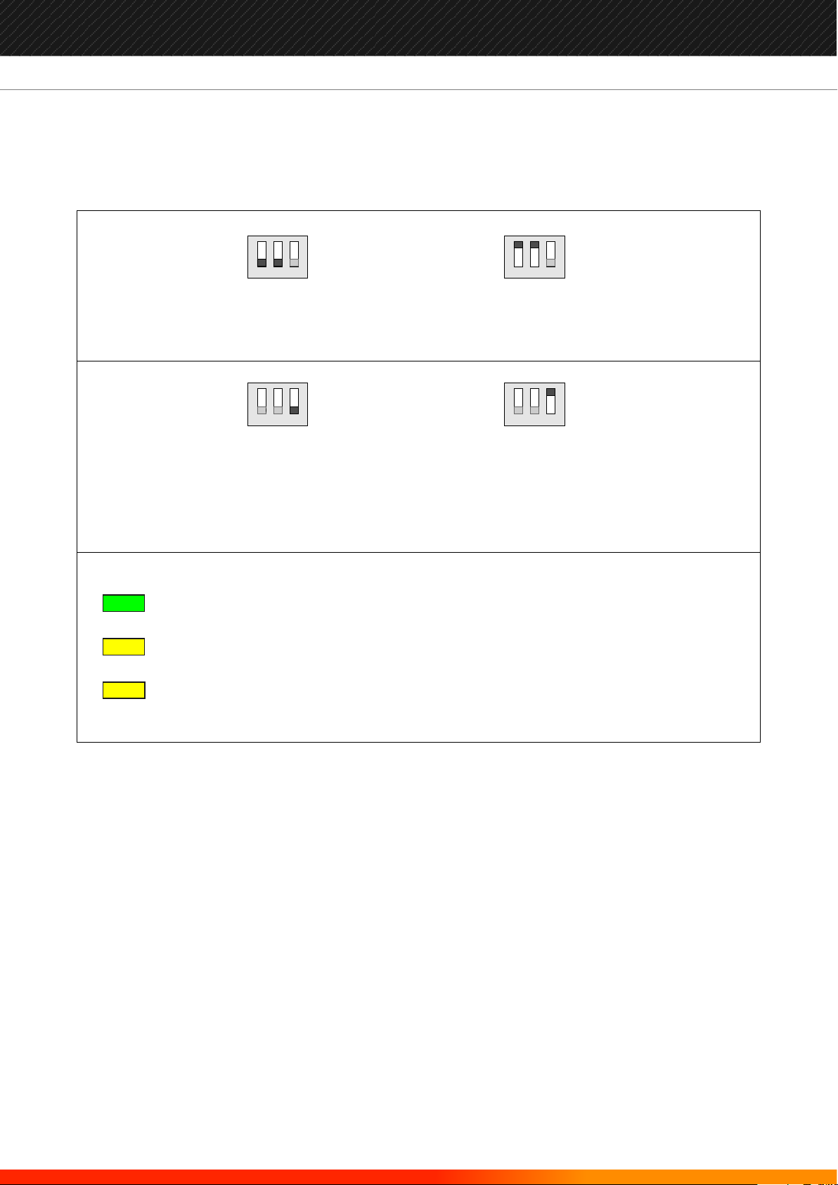
Global Fire Equipment GFE-BCM User manual

INTRODUCTION
This unit is a fully EN54-4 compliant battery charger which also incorporates, in some models, a loop interface that can be
used with all of GFE’s addressable panels. It will monitor all fault conditions including: charger fault, charger voltage level,
input voltage supply fault and supply removal. It can be supplied as a standalone module or boxed in an ABS plastic
enclosure, including a 28V DC @ 1.7 or 2.4 AmpPSU. The standalone unit has 10A current rating and is supplied complete
with heat dissipation.
Battery charge is fully monitored and current output controlled and limited to a maximum of 4 Amps. Two auxillirary
output relays are provided both equipped with a set of changeover contacts. One is used to signal fault conditions. The
Output relay, which is only available for addressable versions, can be used when included in an IO Group.
FEATURES
?Battery Charger Monitored by Addressable Panel
?Fault Relay Output
?Relay O/P Remotely Controlled by Panel
?Low Battery Voltage Shutdown
?Reverse Polarity Protection
?Battery Charger Current Regulated
?LED indicators: Supply Input, Battery & Charger Fault
?Boxed Unit inc. PSU and Battery Compartment
?Fully Compliant with EN54 -4
Manufacturers of Fire Detection Equipment
globalfire.pt
INSTALLATION MANUAL V.3 - 07/2016
GFE-BCM

ADDRESSABLEVERSIONWITH IO UNIT
A
B
C
D
E
F
- Battery Terminal Connections
Connect batteries as shown on page 6 of this manual. Maximum battery capacity for boxed units is 2 x 12V 7Ah batteries.
- Supply Output Terminal Connections
This output supplies a nominal voltage value of 28V DC. Current drive capacity depends on module specification.
- Supply Input Terminal Connections
- Loop Connections
Analogue Loop Connections. Device is not polarity conscious.
- Output relayTerminal Connections
A single pole changeover relay is provided. Activation of relay is possible via panel programming using IO group feature.
Please refer to panel installation manual for further details.
- Fault Relay Terminal Connections
A single pole changeover relay is provided. Activation of relay is caused by any fault detected within the monitoring
circuitry of the module.When device is in fault condition, the analogue value reported to the panel is 2 and it is indicated
by the panel as a supply fault. In these cases both the GENERAL and SUPPLY FAULTS LEDs are ON. Location of the fault is
also provided on the LCD screen where both the Loop and ADDRESS of the device generating the fault are indicated on
the LCD screen.
K1
F1
Battery Fuse
L2 L1
SPLY IN
CN2
ADDRESS
1 2 345678
BAT
K2
BAT FLT
CHAR FLT
OUT
- +- +- +
24V IN
A
B
C
D
NC C NO
FAULT RELAY OUTPUT RELAY
NC C NO
E
F
1 2 3
Manufacturers of Fire Detection Equipment
globalfire.pt
INSTALLATION MANUAL V.3 - 07/2016
GFE-BCM

CONVENTIONALVERSION
A
B
C
D
- Battery Terminal Connections
Connect batteries as shown on page 6 of this manual. Maximum battery capacity for boxed units is 2 x 12V 7Ah batteries.
- Supply Output Terminal Connections
This output supplies a nominal voltage value of 28V DC. Current drive capacity depends on module specification.
- Supply Input Terminal Connections
- Fault Relay Terminal Connections
A single pole changeover relay is provided. Activation of relay is caused by any fault detected
within the monitoring circuitry of the module.
F1
Battery Fuse
SPLY IN
CN2
BAT
K2
BAT FLT
CHAR FLT
OUT
- +- +- +
24V IN
A
B
C
NC C NO
FAULT RELAY
D
1 2 3
Manufacturers of Fire Detection Equipment
globalfire.pt
INSTALLATION MANUAL V.3 - 07/2016
GFE-BCM

SETTINGS
Addressable IO Unit
Units fitted with a built-in addressable IO unit can be directly connected to a device loop on any of GFE’s addressable
panels, via the loop connections.These devices will be monitored directly by the panel.
When fitted, these units will be displayed as IO units and its analogue value monitored by the panel. When there are no
faults on the BCM unit the analogue value reported by the device to the panel is 16 and when in fault condition is 2.
When the device is showing a fault condition, which is always associated with either a fault in the battery charger or
battery voltage as monitored by the module, the panel will also indicate this condition locally by turning ON the
GENERAL FAULT and SUPPLY FAULT LEDs. The LCD of the panel will also display the location of module with a clear
indication of both Loop and Device Address and its associated text label.
Activation of the relay output is accomplished by including the unit in an IO Group. This group can then be assigned to
either a zone or device. Please refer to the Installation Manual of the panel being used for further information regarding
cause and effect programming and functions associated with IO units and groups.
1 2 3
1 2 3
Addressable
SW 2 - OFF
SW 1 - OFF
1 2 31 2 3
SW 3 - OFF
SW 3 - ON
Conventional
SW 2 - ON
SW 1 - ON
SW 3 - OFF When OFF the module will monitor the battery voltage and it will disconnect battery when
below 21V DC avoiding deep discharge.
SW 3 - ON In this case the battery voltage monitoring is disabled.
SPLY IN ON when supply input is present.
CHAR FLT ON when battery charger is faulty or batteries are not connected or faulty.
BAT FLT ON when battery voltage is below 21 V DC.
Manufacturers of Fire Detection Equipment
globalfire.pt
INSTALLATION MANUAL V.3 - 07/2016
GFE-BCM

Battery Connections
It is recommended that the batteries are fitted at the end of commissioning the system otherwise it can be difficult to
remove the power quickly if there is a problem.
The batteries are connected to the GFE-BCM module board. This battery connection not only supplies the module
with power if the primary supply should fail, it also provides a charging output to maintain the batteries in a fully
charged state.
Before connecting the batteries check the voltage across the battery connection terminals. It should be 28.0V +/- 0.5V.
NOTE: arcing and fire risk. Never short circuit the battery terminals. Always connect the blue wire between the
batteries last.
BLACK RED
BLUE
F1
Battery Fuse
- +
BAT OUT 24V IN
1 2 3
- + - +
Replacement Battery Fuse - F1
GFE-BCM-3 (any version)
3 A
5x20 mm
Quick Blow (Fast Acting)
GFE-BCM-10
10 A
5x20 mm
Quick Blow (Fast Acting)
Manufacturers of Fire Detection Equipment
globalfire.pt
INSTALLATION MANUAL V.3 - 07/2016
GFE-BCM

ADDRESS SETTINGS
Switches 1-7
Switch 8
Not used
used to configure the module’s address
ON
OFF
1234 5 6 7 8
ON
OFF
1234 5 6 7 8
Address Switches binary weights
1 on =1
2 on =2
3 on =4
4 on =8
5 on =16
6 on =32
7 on = 64
1234 5 6 7 8 1234 5 6 7 8 1234 5 6 7 8 1234 5 6 7 8 1234 5 6 7 8 1234 5 6 7 8 1234 5 6 7 8 1234 5 6 7 8
01 02 03 04 05 06 07 08
81
1234 5 6 7 8
1234 5 6 7 8 1234 5 6 7 8
89 90
1234 5 6 7 8 1234 5 6 7 8 1234 5 6 7 8 1234 5 6 7 8 1234 5 6 7 8 1234 5 6 7 8
91 92 93 94 95 96
1234 5 6 7 8 1234 5 6 7 8 1234 5 6 7 8 1234 5 6 7 8 1234 5 6 7 8 1234 5 6 7 8 1234 5 6 7 8
82 83 84 85 86 87 88
1234 5 6 7 8 1234 5 6 7 8 1234 5 6 7 8 1234 5 6 7 8 1234 5 6 7 8 1234 5 6 7 8 1234 5 6 7 8 1234 5 6 7 8
73 74 75 76 77 78 79 80
1234 5 6 7 8 1234 5 6 7 8 1234 5 6 7 8 1234 5 6 7 8 1234 5 6 7 8 1234 5 6 7 8 1234 5 6 7 8 1234 5 6 7 8
65 66 67 68 69 70 71 72
1234 5 6 7 8
64
1234 5 6 7 8 1234 5 6 7 8 1234 5 6 7 8
97 98 99
1234 5 6 7 8 1234 5 6 7 8 1234 5 6 7 8 1234 5 6 7 8
105 106 107 108
1234 5 6 7 8 1234 5 6 7 8 1234 5 6 7 8 1234 5 6 7 8 1234 5 6 7 8
113 114 115 116 117
1234 5 6 7 8 1234 5 6 7 8 1234 5 6 7 8 1234 5 6 7 8 1234 5 6 7 8
100 101 102 103 104
1234 5 6 7 8 1234 5 6 7 8 1234 5 6 7 8 1234 5 6 7 8
109 110 111 112
1234 5 6 7 8
55
1234 5 6 7 8
56
1234 5 6 7 8 1234 5 6 7 8 1234 5 6 7 8
46 47 48
1234 5 6 7 8 1 234 5 6 7 8 1 234 5 6 7 8 1 234 5 6 7 8
37 38 39 40
1234 5 6 7 8 1234 5 6 7 8 1234 5 6 7 8 1234 5 6 7 8 1234 5 6 7 8
28 29 30 31 32
1234 5 6 7 8 1234 5 6 7 8 1234 5 6 7 8 1234 5 6 7 8 1234 5 6 7 8 1234 5 6 7 8
19 20 21 22 23 24
1234 5 6 7 8 1234 5 6 7 8 1234 5 6 7 8 1234 5 6 7 8 1234 5 6 7 8 1234 5 6 7 8 1234 5 6 7 8
10 11 12 13 14 15 16
1234 5 6 7 8 1234 5 6 7 8 1234 5 6 7 8 1234 5 6 7 8 1234 5 6 7 8 1234 5 6 7 8
49 50 51 52 53 54
1234 5 6 7 8 1234 5 6 7 8 1234 5 6 7 8 1234 5 6 7 8 1234 5 6 7 8
41 42 43 44 45
1234 5 6 7 8 1 234 5 6 7 8 1 234 5 6 7 8 1 234 5 6 7 8
33 34 35 36
1234 5 6 7 8 1234 5 6 7 8 1234 5 6 7 8
25 26 27
1234 5 6 7 8 1234 5 6 7 8
17 18
1234 5 6 7 8
09
1234 5 6 7 8 1234 5 6 7 8 1234 5 6 7 8 1234 5 6 7 8 1234 5 6 7 8 1234 5 6 7 8 1234 5 6 7 8
57 58 59 60 61 62 63
1234 5 6 7 8 1234 5 6 7 8 1234 5 6 7 8
118 119 120
1234 5 6 7 8 1234 5 6 7 8 1234 5 6 7 8 1234 5 6 7 8 1234 5 6 7 8
121 122 123 124 125
Manufacturers of Fire Detection Equipment
globalfire.pt
INSTALLATION MANUAL V.3 - 07/2016
GFE-BCM

MECHANICAL
REAR CABLE ENTRY
POWER
SUPPLY
UNIT
BATTERIES
Max. Capacity
Lead-Acid VRLA
2 x 12V DC - 7 AH
CONTROL
MODULE
GFE-BCM-3 Electronic Module
Fixing Holes
Electrical Mains
Fused Connector
SUPPLY IN INDICATOR - GREEN
BATTERY CHARGER FAULT INDICATOR - YELLOW
BATTERY VOLTAGE FAULT INDICATOR - YELLOW
TOP CABLE ENTRY
Manufacturers of Fire Detection Equipment
globalfire.pt
INSTALLATION MANUAL V.3 - 07/2016
GFE-BCM

TECHNICAL SPECIFICATIONS
SUPPLY INPUT
SUPPLY OUTPUT
BATTERY CHARGER - CURRENT O/P
BATTERY TYPE
BATTERY FUSE
FAULT RELAY
I/O UNIT - LOOP CURRENT
I/O CONTROLLED RELAY
OPERATING TEMPERATURE
HUMIDITY
PROTECTION
DIMENSIONS
WEIGHT
230 V AC (+10% -15%) - Monitored
1.7 A OR 2.4 A @ 28 V DC nominal
1 A max.
Max. 2 x 12 V 7 AH - Lead Acid VRLA
3 A
Changeover-30 V DC 1 A Resistive
-
-
-10ºC to 50ºC
Max. 95% no condensation
IP21
404 (L) x 242 (W) x 107 (H) mm
1.7 Kg - 7 Kg inc. 2 x 7 AH Bat.
230 V AC (+10% -15%) - Monitored
1.7 A OR 2.4 A @ 28 V DC nominal
1 A max.
Max. 2 x 12 V 7 AH - Lead Acid VRLA
3 A
Changeover - 30 V DC 1 A Resistive
1.7 mA Quiescent - 2.4 mA Fault
Changeover - 240 V AC 10 A Resistive
-10ºC to 50º
Max. 95% no condensation
IP21
404 (L) x 242 (W) x 107 (H) mm
1.7 Kg - 7 Kg inc. 2 x 7 AH Bat.
107 mm
404 mm
242 mm
L2 L1
1 2 345678
BAT OUT
- +- +- +
24V IN
NC C NO NC C NO
1 2 3
131 mm
81 mm
GFE-BCM-3 (1.7 A)
GFE-BCM-3 (2.4 A)
GFE-BCM-3-I/O (1.7 A)
GFE-BCM-3-I/O (2.4 A)
Manufacturers of Fire Detection Equipment
globalfire.pt
INSTALLATION MANUAL V.3 - 07/2016
GFE-BCM

Manufacturers of Fire Detection Equipment
globalfire.pt
INSTALLATION MANUAL V.3 - 07/2016
GFE-BCM
GLOBAL FIRE EQUIPMENT S.A.
Sítio dos Barrabés, Armazém Nave Y, Caixa Postal 908-Z, 8150-016 São Brás de Alportel - PORTUGAL
Tel: +351 289 896 560 • Sales: [email protected] • Technical Support: [email protected] • www.globalfire.pt
Table of contents
Other Global Fire Equipment Monitor manuals