Assembly Instructions
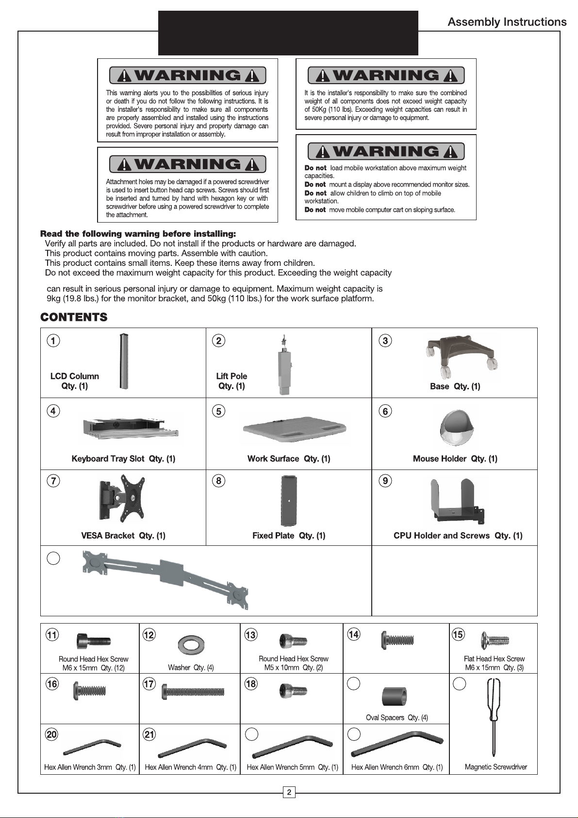
3. CAUTION! Do not remove the gas spring tension retainer
before assembling the lever. Put the lever through the hole on
the side of keyboard tray slot (See Figure A). Turn the lever by
facing up (See Figure B). Once the lever is in position, tighten
two round head hex screws M5 x10mm (13) with a 4mm allen
wrench (21), so that the lever is firmly secured to the keyboard
tray slot (Figure C).
Mouse Holder
Installation
4. Insert mouse holder (6) on
the side of keyboard tray slot
from top to bottom.
Installation
Attaching the Lift Pole
Note: This step may require
assistance. 1. Do not remove the gas
spring tension screw below the label
before completing the assembly. Put
lift pole (2) on the base (3). Note:
Back label must face back of base.
Install four round head hex screws
M6 x15mm (11) each with a washer
(12) through mounting holes in the
base and into lift pole with a 6mm
allen wrench (23) so the lift pole is
firmly attached.
Attaching Keyboard
Tray Slot
2. Put keyboard tray slot (4) on the
lift pole. Install four round head
hex screws M6 x15mm (11) through
mounting holes on the keyboard tray
slot and finally into lift pole with a
6mm allen wrench (23) so that the
keyboard tray slot is firmly attached to
the lift pole. No washers are required
for this portion of the installation.
Lever Installation
2
3
6
23
21
13
11
11
12
Bottom of Base
A B C
Lever
Labels
should
face the
same side
4
3
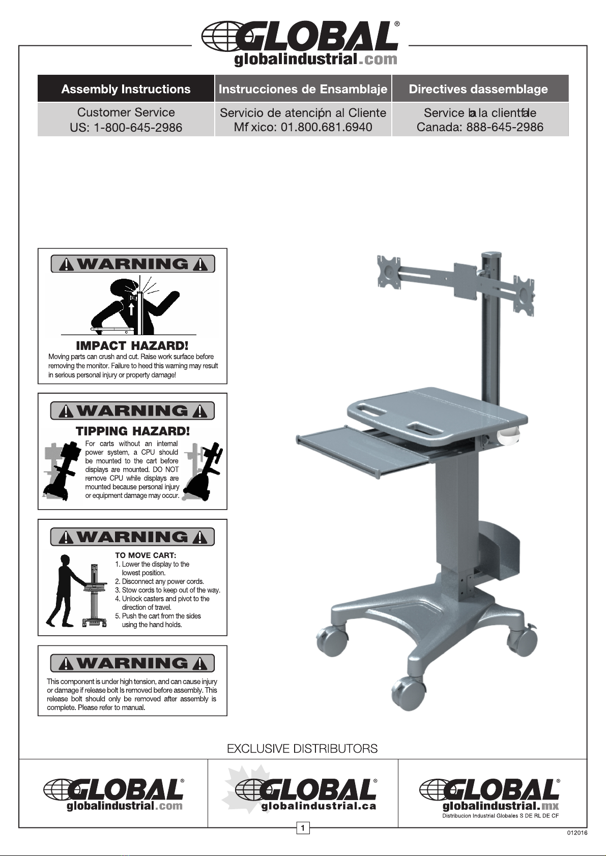
Mobile Sit and Stand Workstation
with Dual Monitor Mount