Global Industrial 246110 User manual

WALL THERMOSTAT
Model: 246110
READ CAREFULLY - These instructions will help prevent difficul-
ties that might arise during thermostat installation.Studying the instruc-
tions first may save considerable time and money later.Observing the
following procedures will keep installation time to a minimum.Save these
instructions for future use.
READ ALL WIRE SIZING, VOLTAGE RE-
UIREMENTS AND SAFETY DATA TO
AVOID PROPERTY DAMAGE AND PER-
SONAL INJURY OR ELECTRIC SHOCK.
READ AND SAVE THESE INSTRUCTIONS
L1 from
power supply
Neutral from
power supply
Line
Red
Load
Black
Thermostat
Wire Connector
Heater
Double Pole Thermostat Installation
1. Disconnect power supply to prevent electrical shock or
damage to product.
2. Run line voltage wiring to the thermostat location.
3.a) Connect the OAD B ACK wire from the thermostat to
the one of wires from the heating unit.
b) Connect another black wire from the thermostat to
another wire from the heating unit.
4.a) Connect the INE RED wire on the thermostat to the
1 line from the supply panel.
b) Connect another red wire from the thermostat to
another wire from the supply panel.
5. Make sure all connections are tight.
6. Insert wires into the junction box, making sure not to
damage wiring.
7.Secure the ground wire to the ground screw provided in
junction box.
8.Remove the thermostat cover by grabbing the cover from
the sides and pulling it away from base.
9. Mount the thermostat into the junction box and secure
using the provided screws.
10. Replace thermostat cover.
The installation of the thermostat must comply with the ap-
plicable local and/or national electrical code and utility re-
quirements. This installation should be performed by a
qualified electrician where required by law. Ensure that all
wiring connections to the thermostat are correct and tight to
prevent electrical shorts. Use the appropriate wire to meet
local and national electrical codes for rated power consump-
tion.
Product Setup and Settings
To adjust the temperature to your requirements, turn the dial
on the thermostat clockwise all the way to turn heater on.
When the room reaches the desired temperature, turn the
thermostat knob counter clockwise until you hear the click.
eave in this position to maintain the room temperature at
this setting. For additional heat, turn clockwise until you
hear the click and the heater will turn on.
- Turning knob fully counter clockwise will disconnect the
power to the heater.
Changing °C and °F control dials.
Use a small flathead screwdriver to pry off the control dial.
Insert into one of the slots on the dial and gentle apply pres-
sure to remove.To install the new control dial, line up the
pins on the dial with the holes on the thermostat knob. Push
together until secured into place.
Specifications:
Thermostat is compatible with electric heaters and electric
garage heaters
Power Supply AC 120V / 208V / 240V / 277V Maximum
Power:
3360W @ 120VAC (28A)
5824W @ 208VAC (28A)
6720W @ 240VAC (28A)
7756W @ 277VAC (28A)
Sensing Element: Bimetal Temperature Operating Range:
41°F-90°F (5°C -32°C)
cET us listing.
Functions And Features
• 120/208/240/277 Volts
•Includes both ºC and ºF control dials
•Wall mount design– Sits flush against wall
•Double Pole – provides positive OFF position
•Disconnects power for extra protection
• arge knob allows easy adjustment to all temperatures
•90°F (32°C) maximum setting
Installation Instructions
Cover Screw
Index Plate Base Outlet Box
Warning: Turn OFF the power at the circuit breaker before
installing. Installation should be performed by a qualified
electrician.
Refer to thermostat and heater load specifications before
installation of the thermostat to see if it can handle the
amp load. The maximum this thermostat can run is 7756
Watts at 277 Volts, 6720 Watts at 240 Volts, 5824 Watts at
208 Volts and 3360 Watts at 120 Volts.
Install unit in a grounded metal or plastic wall junction box,
indoors 4 ½’ to 5’ above the floor. Avoid any area where it
can come in to contact with external sources of heat and
cold. This includes plumbing pipes, direct sunlight, a T.V.
set, lamps, and drafts from a door or window, as this may
cause inaccurate temperature readings. The most conven-
ient place is above the light switch. Not for outdoor use.

THERMOSTAT MURAL
Modèles: 246110
VEUILLEZ LIRE ATTENTIVEMENT - es présentes instruc-
tions vous aideront à éviter certaines difficultés qui pourraient survenir
au moment de l’installation. Prenez connaissance des instructions avant
de commencer l’installation, afin d’éviter les pertes de temps et d’argent.
Vous minimiserez le temps d’installation requis en suivant les procé-
dures indiquées dans le présent guide. Conservez ces instructions pour
usage ultérieur.
VEUILLEZ RESPECTER LES DIRECTIVES DE
SÉCURITÉ ET LES EXIGENCES RELATIVES
AU CÂBLAGE ET À LA TENSION AFIN
D’ÉVITER LES RIS UES DE DOMMAGES
MATÉRIELS, DE DÉCHARGE ÉLECTRI UE
OU DE BLESSURES PERSONNELLES.
CONSERVES CES INSTRUCTIONS
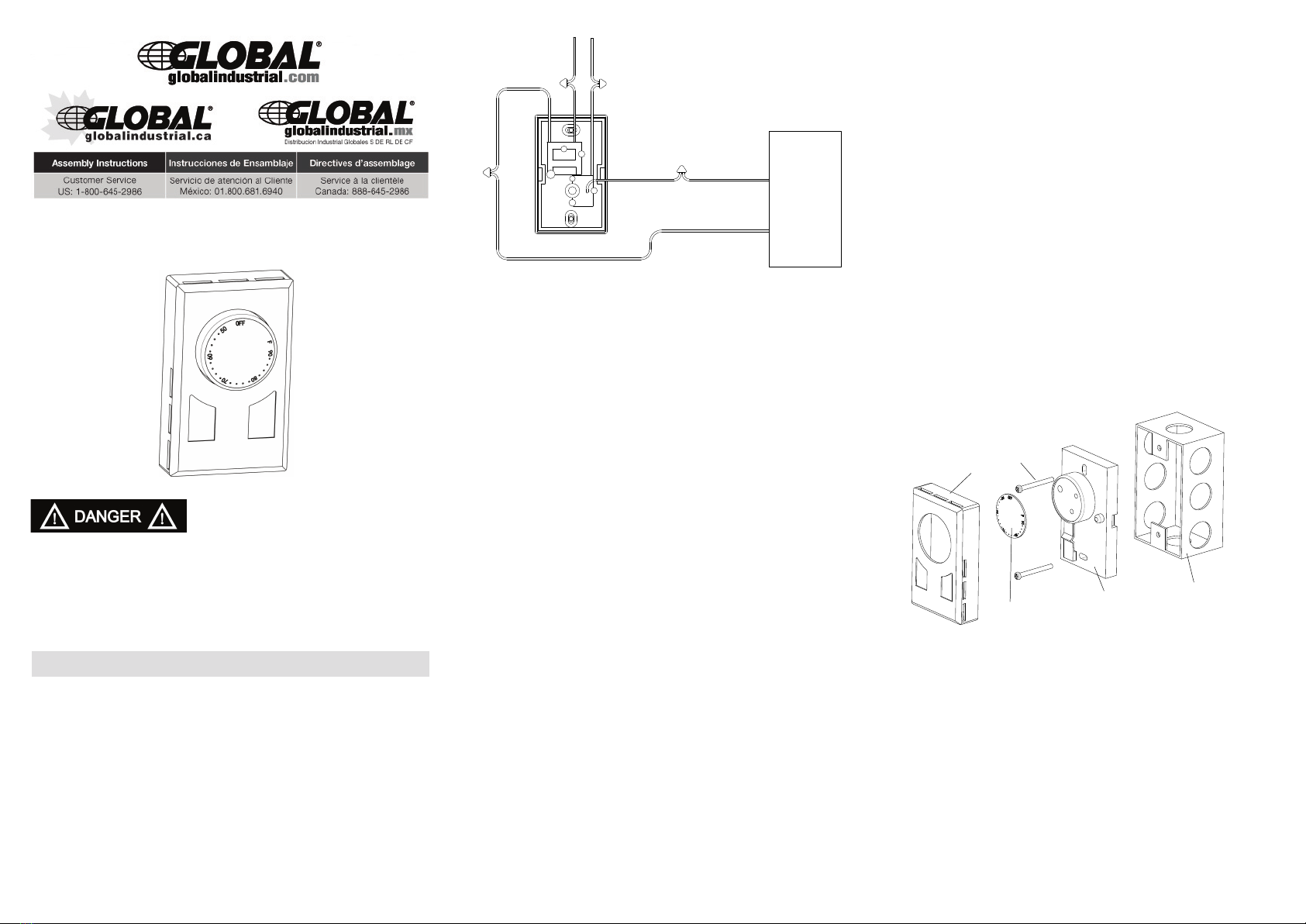
L1 de
L'alimentation
Électrique
Neutre de
L'alimentation
Électrique
Ligne
Rouge
Charger
Noire
Thermostat
Wire Connecteur
Chauffage
Installation Du Thermostat Bipolaire
1.Coupez l’alimentation électrique afin de prévenir les
décharges électriques ou les dommages à l’appareil.
2. Faites passer le fil de tension secteur jusqu’à l’emplacement
du thermostat.
3.a) Connecter la charge noir du thermostat de l'un des fils
de l'unité de chauffage
b) Connectez l'autre fil noir du thermostat d'un câble de
l'unité de chauffage
4.a) Connectez ligne fil rouge sur le thermostat pour le
groupe de l'approvisionnement en 1.
b) Connectez l'autre fil rouge du thermostat d'un câble de
la fourniture d'experts.
5. Vérifiez que toutes les connexions sont serrées.
6. Insérez les fils dans la boîte de jonction en veillant à
ne pas les endommager.
7. Fixez le fil de mise à la terre à la vis de terre dans la
boîte de jonction.
8 .Retirez le couvercle du thermostat en l’agrippant sur les
côtés et en le tirant gors de la base.
9. Posez le thermostat dans la boîte de jonction et fixez-le
en place à l’aide des vis fournies.
10. Remettez le couvercle du thermostat en plcae.
’installation de ce thermostat doit respecter les exigences du
fournisseur de services publices ainsi que les normes d’électric-
ité locales et nationales. ’installation doit être effectuêtrée par
un électricien qualifié là où la loi l’exige. Vérifiez que tous les
branchements électriques au thermostat sont corrects et bien
serrés pour éviter les risques de courts-circuits. Utilisez le
câblage approprié à la consommation électrique de l’appareil,
afin de respecter les normes d’électricité locales et nationales.
Péglage Et Paramètres Du Thermostat
Pour ajuster la température ambiante, tournez le cadran du
thermostat dans le sens horaire jusqu’au bout, afin de mettre
l’appareil de chauffage en marche. orsque la température am-
biante atteint le niveau désiré, tournez le cadran du thermostat
dans le sens antihoraire jusqu’à ce que vous entendiez un clic.
aissez le thermostat à ce réglage pour maintenir la tempéra-
ture ambiante. Pour réchauffer la pièce,tournez le cadran du
thermostat jusqu’à ce que vous entendiez un clic, l’appareil de
chauffer se metta alors en marche.
- Pour arrêter complètement l’appareil de chauffage, tournez le
cadran du thermostat dans le sens antihoraire, jusqu’au bout.
Pour changer les cadrans de réglage en °C et en °F.
Utilisez un petit tournevis à tête plate pour retirer le cadran. In-
sérez le tournevis dans l’une des fentes du cadran et retirez
celui-ci en appliquant une légère pression. Pour installer l’autre
cadran, faites correspondre les tiges du cadran avec les ouver-
tures dans le bouton du thermostat. Poussez le cadran jusqu’à
ce qu’il soit bien fixé en place.
Spécifications
e thermostat est compatible avec les appareils de chauffage
électriques et les radiateurs pour garge.
Alimentation électrique: AC 120V / 208V / 240V / 277V
Puissance maximale:
3360W @ 120VAC (28A)
5824W @ 208VAC (28A)
6720W @ 240VAC (28A)
7756W @ 277VAC (28A)
Élément de détection bimétallique Gamme de température de
fonctionnement: 41°F à 90°F (5°C -32°C)
Homologué cET us.
Fonctions Et Caractéristiques
• 120/208/240/277 Volts
•Cadrans de réglage en ºC et ºF inclus
•Installation murale – posé à plat contre le mur
•Bipolaire – fournit une position d’arrêt positif
•Coupe l’alimentation pour une protection supplémentaire
•Grand bouton pour un ajustement facile à toutes les tempéra-
tures
•Réglage maximal de 90°F (32°C)
Directives D’installation
Couvrir Visser
Index des tôles Base Outlet Box
Avertissement: Coupez l’alimentation électrique au panneau élec-
trique principal avant de commencer l’installation. ’installation de-
vrait être effectuée par un électricien qualifié. Consultez les
spécifications électriques du thermostat et de I’appareil de
chauffage avant d’installer le thermostat, afin de vérifier que celui-ci
pourra bien supporter la charge. a puissance maximale pouvant
être acceptée par ce thermostat est : 7756 Watts à 277 Volts, 6720
Watts à 240 Volts, 5824 Watts à 208 Volts ou 3360 Watts à 120
Volts.
Installez le thermostat dans une boîte de jonction en métal ou en
plastique avec mise à la terre, dans un endroit à l’intérieur, à 4 ½’
ou 5 pieds au-dessus de sol. Évitez les endroits où le thermostat
pourrait entrer en contact avec des sources de chaud ou de froid,
incluant les tuyaux de plomberie, l’ensoleillement direct, un
téléviseur, une lampe ou une brise provenant d’une fenêtre ou
d’une porte ouverte; ceci pourrait fausser la lecture de la tempéra-
ture. ll est recommandé d’installer le thermostat au-dessus de l’in-
terrupteur mural. e thermostat ne doit pas être installé à l’extérieur.

TERMOSTATO DE LA PARED
Modelo: 246110
Leer atentamente -Estas instrucciones le ayudará a prevenir las
dificultades que puedan surgir durante la instalacion del termostato.
Estudiando las instrucciones primer puede ahorrar mucho tiempo y
dinero mas adelante.Observando los siguientes procedimientos va a
mantener el tiempo de instalación a un mínimo.
Guarde estas instrucciones para uso futuro.
LEER TODAS LAS SECCIONES DE CABLE,
RE UERIMIENTOS DE VOLTAJE Y LOS
DATOS DE SEGURIDAD PARA EVITAR
DAÑOS A LA PROPIEDAD Y LESIONES
PERSONALES.
LEA Y GUARDE ESTAS INSTRUCCIONES
L1 de
Suministro
de Energía
Neutral de
Suministro
de Energía
Línea
Roja
Carga
negro
Thermostato
Conector de Cable
Calentador
Instalacion Doble Polo Termostato
1.Desconecte el suministro de energía para prevenir
descarga eléctrica o daño al producto.
2. Correr tensión de línea cableado para el termostato.
3.a) Conectar la carga cable negro desde el termostato al uno
de los cables de la unidad de calefaccion
b) Conectar un cable negro desde el termostato a otro
cable de la unidad de calefaccion
4.a) Conectar la línea cable rojo en el termostato a la 1
línea desde el panel de suministro.
b) Conectar otro cable rojo desde el termostato a otro cable
de suministro panel.
5. Asegúrese de que todas las conexiones son apretados.
6. Inserte los cables en la caja de conexiones,
asegurándose de que no dañar el cableado.
7. Asegure el cable de tierra a la planta de tornillo
suministrado en caja de conexiones.
8. Quitar el termostato cubrir por el acaparamiento de la
cubierta de los lados y tirar lejos de la base.
9. Monte el termostato en la caja de conexiones y segura
utilizando los tornillos suministrados.
10. Replace termostato cubrir.
a instalacion del termostato debe cumplir con las leyes
locales y / o código eléctrico nacional y la utilidad requisi-
tos.Esta instalación debe ser realizado por un electricista
cualificado cuando sea requerido por la ley.Asegurarse de
que todas las conexiones de cableado para el termostato
son correctos y apretado para evitar cortocircuitos eléctri-
cos.Utilice el cable adecuado para satisfacer los códigos
eléctricos locales y nacionales para el consumo de energia.
Instalación Y Configuración De Producto
Para ajustar la temperatura a tus requisitos, gire el dial en el
termostato del calentador para girar en sentido de las agu-
jas del reloj todo el camino.Cuando la habitación alcanza la
temperatura deseada, gire el mando del termostato en sen-
tido antihorario hasta oír el clic.Dejar en esta posición para
mantener la temperatura de la habitacion en esta configu-
ración.Para el calor adicional, girar en sentido horario hasta
que escuchas el click y el calentador se enciende.
- Girando la perilla completamente en sentido antihorario se
desconecte la energía del calentador.
Cambiando °C y °F diales de control.
Utilice un pequeño destornillador de cabeza plana para
alzaprimar el dial de control.Insertar en una de las ranuras
en el dial y la suave presión de quitar.Para instalar el nuevo
dial de control, la linea de los pines en el dial con los agu-
jeros en el mando del termostato.Empujar juntos hasta el
acreedor en su lugar.
Especificaciones
El termostato es compatible con calentadores electricos y calen-
tadores de garaje electrica
Power Supply AC 120V / 208V / 240V / 277V potencia máxima:
3360W @ 120VAC (28A)
5824W @ 208VAC (28A)
6720W @ 240VAC (28A)
7756W @ 277VAC (28A)
Elemento de detección: bimetal temperatura rango de operación:
41°F - 90°F (5°C -32°C)
cET us listado..
Funciones Y Características
• 120/208/240/277 Volts
• Incluye tanto ºC o ºF diales de control
• Diseño de montaje en la pared, se encuentra a ras contra
la pared
• Doble polo – Proporciona positiva posición de apagado
• Se desconecta el poder para protección adicional
• Boton grande permite un facil ajuste para todas las
temperaturas
• os 32°C (90°F) máximo
Instrucciones De Instalación
Cover Tornillo
El indice de
placa
Base Caja de salida
Advertencia: apagar el poder en el Circuit Breaker antes de in-
stalar. a instalacion debe ser realizada por un electricista cuali-
ficado.
Consulte las especificaciones de carga y termostato calentador
antes de la instalacion del termostato para ver si puede manejar
el amplificador de carga.El máximo de este termostato puede
correr es 7756 Watts en 277 voltios, 2700 Watts a 240 voltios,
5824 Watts en 208 voltios y 3360 Watts A 120 voltios.
Instalar la unidad en una funda de plástico o metal wall Junction
box, interior 4 ½ 'a 5' sobre el suelo.Evitar la zona donde pueda
entrar en contacto con fuentes externas de calor y frio.Esto in-
cluye tuberías, luz solar directa, TV set, lámparas, y de proyec-
tos a partir de una puerta o ventana, como esto puede causar
inexactas las lecturas de temperatura.El lugar mas conveniente
es sobre el interruptor de la luz.No para el uso al aire libre.
Table of contents
Languages:
Other Global Industrial Thermostat manuals