Page 3 of 24 Rev: 8/30/2012 11:41 AM
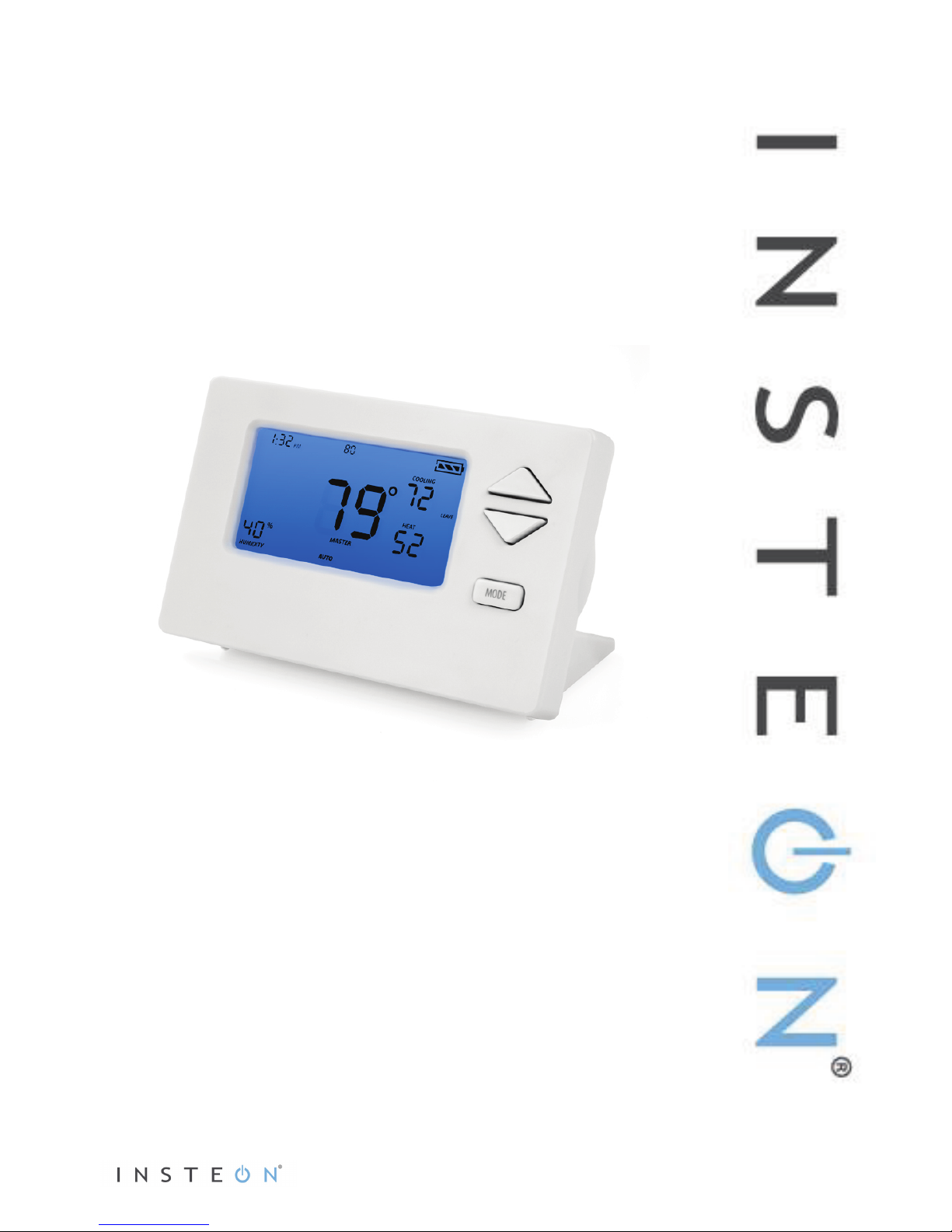
About INSTEON Wireless Thermostat
INSTEON Wireless Thermostat is a wireless, battery-operated, one-day programmable, INSTEON-
compatible thermostat. INSTEON Wireless Thermostat includes a humidity sensor and the ability to
communicate via RF to other INSTEON devices, including INSTEON Thermostat.
INSTEON Wireless Thermostat is not directly wired to the HVAC (Heating Ventilating and Air
Conditioning) system. If you want to control the HVAC system with INSTEON Wireless Thermostat, you
need to install at least one INSTEON Thermostat, then link INSTEON Wireless Thermostat as a wireless
controller of INSTEON Thermostat.
INSTEON Wireless Thermostat may also be used as a standalone INSTEON controller of other
INSTEON responders, activating scenes to turn on standalone heaters and fans based on room
temperature status.
Expand your INSTEON thermostat system by creating extra temperature zones in your home with
additional INSTEON Wireless Thermostats. Simply link each accessory INSTEON Wireless Thermostat to
your main INSTEON Thermostat and primary INSTEON Wireless Thermostat.
INSTEON Wireless Thermostat – Features and Benefits
•Installs in minutes in included tabletop stand (can also be wall-mounted)
•Can be added to scenes as a controller of INSTEON devices
•Saves energy and money on bills by remotely controlling and automating your thermostat
•Communicates wirelessly over radio frequency (RF)
•Can automatically control INSTEON devices and activate scenes when specified temperatures,
humidity levels or A/C or heating modes are detected
•Reports changes in thermostat modes, temperature, humidity, setpoints and fan to compatible
automation controllers or software
•Stores setup state in non-volatile memory so settings aren’t lost during battery changes or power
outages
•Two-year warranty
•Battery features:
oGoes into battery-saving standby mode one minute after last button press
oWakes up every minute to get current local temp info, which remains displayed in
standby
oLow battery warning beeper
oBroadcasts temperature or humidity changes to other connected devices
•When connected to always-on power supply:
oRemains awake always rather than going to standby
oParticipates in the INSTEON network as a message hopper
oGood for hard-to-reach locations where battery changes may be difficult
What’s in the Box?
•INSTEON Wireless Thermostat
•Quick Start Guide
•Tabletop stand (removable for wall-mounting)