www.globallightllc.com info@globallightllc.com Fax: +971 4 341 10 90Tel: +971 4 340 44 58
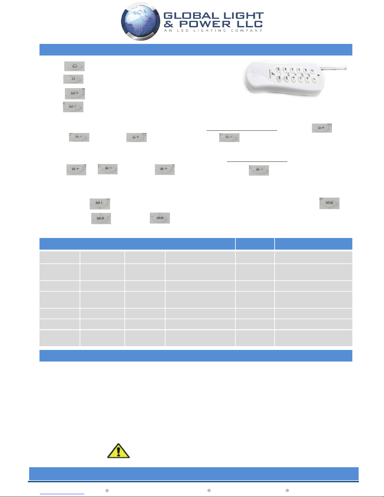
1. ON/OFF Button.
2. Pause Button, will pause on any colour during a scene.
3. Switch between modes starting from 1 (Static Red).
4. Switch between modes backwards, but first mode would be red and then count down from
sequence 16.
5. Once the desired mode is set, you may increase the speed of color changing by pressing
or button. The button will increase and will reduce the speed of color
changing.
6. Once the desired color mode is set, you may increase the intensity or brightness of LED’s by pressing
or button. The button will increase and will reduce the brightness or
intensity of LED’s.
7. Preset mode 1, after adjusting the light to your preferred setting, you can then save it by pressing and
holding button on the remote for 3 seconds. Same procedure applies for mode 2 ,
mode 3 and mode 4 .
#You can customize and save up to 4 modes of your own.
Key Functions of Wireless Remote Control
Table of Changing Modes
Sequence Modes Sequence Modes Sequence Modes
1 Static Red 7 Static White 13 RED/Green Smooth
Variation
2 Static Green 8 RGB Quick Variation 14 Red/Blue Smooth Variation
3 Static Blue 9 7 Color Quick Variation 15 Green/ Blue Smooth
Variation
4 Static Yellow 10 White light effect Strobe 16 White Smooth Variation
5 Static Purple 11 RGB Smooth Variation
6 Static Cyan 12 All modes Smooth
Variation
A. Press PAUSE for 3s, the buzzer will turn on or off.
B. Press MODE+ for 3s to activate automatic variation for all the modes.
C. Press MODE- for 3s to activate 4 scene modes. The color variations will occur between the non-static
modes.
D. Press SPEED+ for 3s, to restore the speed of all modes to default settings.
E. Press SPEED- for 3s, to restore the currently in use mode to default settings.
Special Functions of Wireless Remote Control
#Note: Static modes are only affected by brightness controls, Variation modes are affected by both brightness/ speed controls.
Please read the instructions carefully before
installation, and keep them for your future reference.
All installation and maintenance must be carried out by qualified engineers