Global Pumps TSP Series User manual

INSTALLATION, OPERATION,
& MAINTENANCE MANUAL
WITH PARTS LIST
TSP SERIES SELF PRIMING PUMP
MODEL
TSP-80

TABLE OF CONTENTS
Parts list
Performance curve
19
PUMP MAINTENANCE AND REPAIR-SECTION E
19
Preventive maintenance
18
TROUBLESHOOTING-SECTION
D
15
Bearing temperature check
14
Cold weather preservation
14
Stopping
14
Pump
vacuum check
14
Strainer check
13
Liquid temperature and overheating
13
Leakage
13
Lines without a bypass
13
Lines with a bypass
13
Operation
13
Rotating
12
Starting
12
Priming
12
OPERATION-SECTION C
12
V-belt drives
11
Coupled drives
10
Alignment
10
Air release valve installation
9
Automatic air release valve
8
Bypass lines
8
Valves
8
Siphoning
8
Discharge lines
8
Suction line Positioning
7
Suction lines in Sump
6
Sealing
6
Strainers
6
Fittings
6
Suction Lines
6
Gauges
6
Connections to pump
6
Line
Configuration
6
Materials
6
SUCTION
AND
DISCHARGE
PIPING
6
Clearance
5
Mounting
5
Lifting
5
POSITIONING
PUMP
5
PREINSTALLATION
INSPECTION
5
Pump
Dimensions
4
INSTALLATION
−
SECTION
B
4
SAFETY
−
SECTION
A
2
1
INTRODUCTION
20

Pump model
21
Rotating assembly
22
Pump and seal disassembly and reassembly
24
Back cover and wear plate removal
24
Suction check valve removal
25
TABLE OF CONTENTS (continued)
Rotating assembly removal
25
Impeller removal
26
Shaft and bearing removal and disassembly
26
Shaft and bearing reassembly and installation
27
Seal installation
28
Impeller installation and adjustment
30
Rotating assembly installation
30
Suction check valve installation
31
Back cover installation
31
42
PRESSURE RELIEF VALVE
32
Final pump assembly
32
LUBRICATION
32
Seal assembly
32
Bearings 32

1
INTRODUCTION
Thank You for purchasing a TORO pump. Read this
manual carefully to learn how to safely install and
operate your pump. Failure to do so could result in
personal injury or damage to the pump.
Because pump installations are seldom identical, this
manual cannot possibly provide detailed instructions
and precautions for every aspect of each specific
application. Therefore, it is the responsibility of the
owner/installer of the pump to ensure that
applications not addressed in this manual are
performed only after establishing that neither
operator safety nor pump integrity are compromised
by the installation. Pumps and related equipment
must be installed and operated according to all
national, local and industry standards.
If there are any questions regarding the pump or its
application which are not covered in this manual or in
other literature accompanying this unit, please
contact your TORO distributor;
Global Pump Group Pty Ltd
12 Selgar Avenue, Tonsley
South Australia, 5042, AUSTRALIA
Phone: +61 8 8275 8000
For information or technical assistance on the power
source, contact the power source manufacturer's
local dealer or representative.
HAZARD AND INSTRUCTION
DEFINITIONS
The following are used to alert maintenance
personnel to procedures which require special
attention, to those which could damage equipment,
and to those which could be dangerous to
personnel:
Immediate hazards which WILL result
in severe personal injury or death.
These instructions describe the
procedure required and the injury
which will result from failure to follow
the procedure.
Hazards or unsafe practices which
COULD result in severe personal
injury or death. These instructions
describe the procedure required and
the injury which could result from
failure to follow the procedure.
Hazards or unsafe practices which
COULD result in minor personal injury or
product or property damage. These
instructions describe the requirements
and the possible damage which could
result from failure to follow the procedure.
NOTE
Instructions to aid in installation, operation, and
maintenance or which clarify a procedure.

SAFETY
SAFETY −SECTION A
This information applies to TSP series basic
pumps. TORO has no control over or
knowledge of the power source which will be
used. Refer to the manual accompanying the
power source before attempting to begin
operation.
This manual will alert personnel to known
procedures which require special attention,
to those which could damage equipment,
and to those which could be dangerous to
personnel. However, this manual cannot
possibly provide detailed instructions and
precautions for each specific application or
for every situation that might occur during
maintenance of the unit. Therefore, it is the
responsibility of the owner, installer and/or
maintenance personnel to ensure that
applications and/or maintenance
procedures not addressed in this manual
are performed only after establishing that
neither personal safety nor pump integrity
are compromised by such applications or
procedures.
Before attempting to open or service the
pump:
1.
Familiarize yourself with this manual.
2.
Disconnect or lock out the power
source to ensure that the pump will
remain inoperative.
3.
Allow the pump to completely cool if
overheated.
4.
Check the temperature before opening
any covers, plates, or plugs.
5.
Close the suction and discharge
valves.
6.
Vent the pump slowly and cautiously.
7.
Drain the pump.
This pump is designed to handle liquids
containing large entrained solids or slurries.
Do not attempt to pump volatile, corrosive,
or flammable materials which may damage
the pump or endanger personnel as a result
of pump failure.
Death or serious personal injury and
damage to the pump or components can
occur if proper lifting procedures are not
observed. Make certain that hoists,
chains, slings or cables are in good
working condition and of enough capacity
and that they are positioned so that loads
will be balanced, and the pump or
components will not be damaged when
lifting. Suction and discharge hoses and
piping must be removed from the pump
before lifting. Lift the pump or component
only as high as necessary and keep
personnel away from suspended objects.
After the pump has been positioned, make
certain that the pump and all piping
connections are tight, properly supported
and secure before operation.
PAGE 2
to cool before servicing.
ejected
with
great
force.
Allow
the
pump
cause
parts
being
disengaged
to
be
pump. Vapor
pressure within the
pump can
pipe plugs, or fittings from an
over-
heated
Do
not
remove
plates,
covers,
gauges,

SAFETY
Overheated pumps can cause severe burns
and injuries. If overheating of the pump
occurs:
1.
Stop the pump immediately.
2.
Ventilate the area.
3.
Allow the pump to completely cool.
4.
Check the temperature before opening
any covers, plates, gauges, or plugs.
5.
Vent the pump slowly and cautiously.
6.
Refer to instructions in this manual
before restarting the pump.
Never run this pump backwards. Be certain
that rotation is correct before fully
engaging the pump.
Pumps and related equipment must be in-
stalled and operated according to all
national, local and industry standards.
PAGE 3
cause the pump casing to rupture or
explode.
liquid could
come
to a boil, build pressure, and
pump components
will
deteriorate, and the
operated
against
a
closed
discharge valve,
discharge valve
for long
periods
of
time.
If
Do not operate the pump
against
a
closed
personnel.
fingers,
or
tools, causing severe injury to
Exposed rotating parts can catch
clothing,
guards
in
place
over
the
rotating
parts.
Do
not
operate
the
pump
without
the

SAFETY
INSTALLATION –SECTION B
mounting, line configuration, and priming must be tai
lored to the specific application. Since the pressure
supplied
to the pump is critical to
performance and safetybe sure to limit the incoming
pressure to 50% of the maximum permissible oper
ating pressure as shown on the pump performance
curve.
For further assistance, contact your TORO distributor
or TORO Company.
Pump Dimensions
See Figure 1 for the approximate physical dimensio
ns of this pump.
OUTLINE DRAWING
Figure 1 - PUMP MODEL TSP-80 8"
PAGE 4
pressure,
some
of
the
information
such
as
where
the
liquid
is
supplied
to
the
pump
under
If
installed
in
a
flooded
suction
application
above
the
free
level
of
liquid
to
be
pumped.
static
lift
application
where
the
pump
is
positioned
Most
of
the
information
pertains
to
a
standard
the
pump
and
piping.
practices
required
to
inspect,
position,
and
arrange
section
offers
only
general
recommendations
and
Since
pump
installations
are
seldom
identical,
this
Review
all
SAFETY
information
in
Section
A.

SAFETY
PREINSTALLATION INSPECTION
The pump assembly was inspected and tested before
shipment from the factory. Before installation, inspect
the pump for damage which may have occurred during
shipment. Check as follows:
a)Inspect the pump for cracks, dents, damaged
threads, and other obvious damage.
b)Check for and tighten loose attaching hardware.
Since gaskets tend to shrink after drying, check
for loose hardware at mating surfaces.
c) Carefully read all warnings and cautions
contained in this manual or affixed to the pump,
and perform all duties indicated. Note the
direction of rotation indicated on the pump.
Check that the pump shaft rotates
counterclockwise when facing the impeller.
Only operate this pump in the direction
indicated by the arrow on the pump body
and
on the accompanying decal. Refer to
Rotation in OPERATION, Section C.
d) Check levels and lubricate as necessary. Refer
to LUBRICATION in the MAINTENANCE AND
REPAIR section of this manual and perform
duties as instructed.
e) If the pump and power source have been stored
for more than 12 months, some of the
components or lubricants may have exceeded
their maximum shelf life. These must
be
inspected or replaced to ensure maximum
pump service.
If the maximum shelf life has been exceeded, or if
anything appears to be abnormal, contact your TORO
distributor or the factory to determine the repair or
updating policy. Do not put the pumpinto service until
appropriate action has
been taken.
POSITIONING PUMP
Death or serious personal injury and
damage to the pump or components can
occur if proper lifting procedures are not
observed. Make certain that hoists, chains,
slings or cables are in good working
condition and of sufficient capacity and
that they are positioned so that loads will
be balanced, and the pump or components
will not be damaged when lifting. Suction
and discharge hoses and piping must be
removed from the pump before lifting. Lift
the pump or component only as high as
necessary and keep personnel away from
suspended objects.
Lifting
Pump unit weights will vary depending on the mounting
and drive provided. Check the shipping tag on the unit
packaging for the actual weight and
use lifting equipment
with appropriate capacity.
Drain the pump and remove
all customer-installed equipment such as suction and
discharge hoses or piping before attempting to lift
existing,installed units.
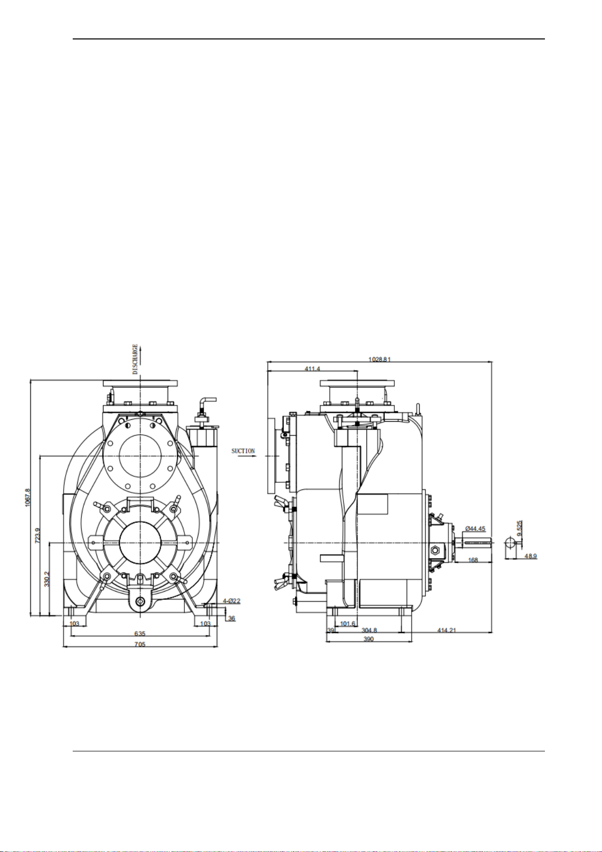
Mounting
Locate the pump in an accessible place as close as
practical to the liquid being pumped. Level mounting is
essential for proper operation.
The pump may have to be supported or shimmed to
provide for level operation or to eliminate vibration.
Clearance
It is recommended that 18 inches (457 mm) of clearance
be provided in front of the back cover to permit removal
of the cover and easy access to the
pump interior. A minimum clearance of 8 inches (203
mm) must be maintained to permit removal of the cover.
PAGE 5

SAFETY
SUCTION LINES
To avoid air pockets which could affect pump priming, the
suction line must be as short and direct as
possible.
When operation involves a suction lift, the
line must
always slope upward to the pump from the source of the
liquid being pumped; if the line slopes down to the pump
at any point along the suction run, air pockets will be
created.
PAGE 6
Most
pumps
are
drilled
and
tapped
for
installing
Gauges
liquid
and
under
pressure.
have adequate
support
to
secure
them
when
filled
with
and seal
wear.
If
hose-type lines
are
used, they should
vibration,
decreased
bearing
life,
and
increased
shaft
strain
on
the
pump
which
could
cause
excessive
the
pump
must
be
independently
supported
to
avoid
tightening the flange bolts
and/or
couplings.
Lines near
with
the
pump
port.
Never
pull
a
pipeline
into
place
by
Before
tightening
a
connecting
flange,
align
it
exactly
Connections to
Pump
minimize friction loss.
elbows
are
necessary,
use
the
long-radius
type
to
and
fittings,
which
substantially
increase
friction
loss.
If
to minimize friction losses. Make
minimum use of elbows
Keep suction and discharge lines as straight
as
possible
Line
Configuration
suction lines is not
recommended.
prevent collapse under suction.
Using piping couplings in
in
suction lines,
it
must
be the
rigid-wall, reinforced type to
compatible
with
the
liquid being pumped.
If
hose
is
used
discharge
lines;
however,
the
materials
must
be
Either
pipe
or
hose
maybe
used
for
suction
and
Materials
pump to
operate
within the safe operation
range.
Page
19
to
be
sure
your
overall
application
allows
the
the
performance
curve
and
operating
range
show
on
suction lift, discharge elevation, and
friction losses. See
Pump
performance
is
adversely
affected
by
increased
SUCTION AND DISCHARGE
PIPING
in
erratic
readings.
install the
lines. Installation closer to
the pump may result
18”
(450
mm)
from
the
suction and discharge ports and
and
tap the
suction and
discharge
lines
not
less
than
gauges are desired for pumps that are
not
tapped, drill
discharge
pressure
and
vacuum
suction
gauges.
If
these
least 3 times the diameter of
the suction
pipe.
so
that they are separated by a
distance equal to at
or both pumps.
To
avoid this, position
the suction inlets
flow
paths
may
interact,
reducing
the
efficiency
of one
If two suction lines are installed in a single sump,
the
the liquid before it is drawn
into
the suction
inlet.
pipe. The baffle will allow
entrained air to escape from
inlet at a distance 1½
times
the
diameter
of the suction
inlet,
install
a
baffle
between
the
inflow
and
the
suction
If
it
is
necessary
to
position
inflow
close
to
the
suction
pump
efficiency.
sump, and air entering
the suction line will
reduce
inlet
because
the
inflow
will
carry
air
down
into
the
sump,
the
flow should be kept away from the
suction
If there is a liquid flow from an open pipe into
the
equal
to
1½
times
the
diameter ofthe suction
line.
positioned
away
from
the
wall
of
thesump at
a
distance
If
a
single
suction
line
is
installed
in
a
sump
itshould
be
Suction
Lines
in
Sumps
should be
compatible
with the liquid being
pumped.
selecting
and
applying
the
pipe
dope.
The
pipe
dope
sealant
manufacturer’s
recommendations
when
with
pipe
dope
to
ensure
an
airtight
seal.
Follow
the
lift,
all connections in the suction
line should be sealed
capacity, especially when operating with
a
high suction
Since
even
a
slight
leak
will
affect
priming,
head,
and
Sealing
diameter spherical solids.
This
pump
is designed
to
handle
up
to
1½”
(38mm)
larger than the solids handling
capability
of the
pump.
and that the openings will not permit
passage
of solids
three
or four times the cross section of the
suction
line,
total area
of
the
openings
in
the
strainer
is
at
least
but
is installed
by
the
pump
user,
make
certain
that
the
itself.
If
a
strainer
is
not
furnished
with
the
pump,
furnished with the pump will also
pass through the pump
any
spherical
solids
which
pass
through
a
strainer
If a strainer is furnished with the pump, be
certain to
useit;
Strainers
air
pockets.
valve is
used,
install it with the stem horizontal to avoid
Valves
are
not
normally
used
in
suction
lines,
but
if
a
of the reducers
uppermost
to avoid creating air pockets.
eccentric type, and should be
installed with the flat part
If
reducers
are
used
in
suction
lines,
they should be the
Suction
lines should
be the
same size
as the
pump
inlet.
Fittings

SAFETY
Suction Line Positioning
The depth of submergence of the suction line is
critical to efficient pump operation. Figure 2 shows
recommended minimum submergence vs. velocity.
NOTE
The pipe submergence required may be reduced by
installing a standard pipe increaser fitting at the end of
the suction line. The larger opening size will reduce the
inlet velocity. Calculate the required submergence
using the following formula based on the increased
opening size (area or diameter).
Figure 2 -Recommended Minimum Suction Line Submergence vs. Velocity
PAGE 7

SAFETY
DISCHARGE LINES
Siphoning
Do not terminate the discharge line at a level lower
than that of the liquid being pumped unless a siphon
breaker is used in the line. Otherwise, a siphoning
action causing damage to the pump
could result.
Valves
If a throttling valve is desired in the discharge line, use
a valve as large as the largest pipe to minimize friction
losses. Never install a throttling valve in a
suction line.
With high discharge heads, it is recommended that a
throttling valve and a system check valve be installed
in the discharge line to protect the pump
from
excessive shock pressure and reverse rotation when
it is stopped.
If the application involves a high discharge head,
gradually close the discharge throttling valve before
stopping the pump.
Bypass Lines
Self-priming pumps are not air compressors. During
the priming cycle, air from the suction line must be
vented to atmosphere on the discharge side. If the
discharge line is open, this air will be vented through
the discharge. However, if a check valve has been
installed in the discharge line, the discharge side of
the pump must be opened to atmospheric pressure
through a bypass line installed between the pump
discharge and the check valve. A self-priming
centrifugal pump will not prime if there is sufficient
static liquid head to hold the discharge check valve
closed.
NOTE
The bypass line should be sized so that it does not
affect pump discharge capacity; however, the bypass
line should be at least 1”(25.4 mm) in diameter to
minimize the chance of plugging.
In low discharge head applications (less than 30’or
9 meters), it is recommended that the bypass line be
run back to the wet well and located 6
inches below the
water level or cut-off point of the low-level pump. In
some installations, this bypass line may be terminated
with a six to eight-foot length of 1¼”I.D.
smooth-bore
hose; air and liquid vented during the priming process
will then agitate the hose and break up any solids,
grease, or other substances likely to cause clogging.
A bypass line that is returned to a wet well must be
secured against being drawn into the pump suction
inlet.
It is also recommended that pipe unions be installed
at each 90° elbow in a bypass line to ease disassemble
and maintenance.
AUTOMATIC AIR RELEASE VALVE
In
high discharge head applications
(more than
30’or 9 meters), an excessive amount of liquid may be
bypassed and forced back to the wet
well under the
full working pressure of the pump; this will reduce
overall pumping efficiency. Therefore, it is
recommended that a TORO Automatic Air Release
Valve be installed in the
bypass line.
TORO Automatic Air Release Valves are
reliable and
require minimum maintenance. See
AUTOMATIC AIR
RELEASE VALVE in this section for installation and
theory of operation of the Automatic Air Release Valve.
Consult your TORO distributor for selection of an
Automatic Air Release
Valve to fit your application.
If the installation involves a flooded suction such as a
below-ground lift station. A pipe union and manual shut
‐off valve may be installed in the bleed line to allow
service of the valve without shutting down the station,
and to eliminate the possibility of flooding. If a manual
shut‐off valve is installed anywhere in the air release
piping, it must be a full opening ball type valve to
prevent plugging by solids.
PAGE 8

SAFETY
A manual shut-off valve should not be
installed in any bypass line. A manual
shut-off valve may inadvertently be left
closed during operation. A pump which
has lost prime may continue to operate
without reaching prime, causing
dangerous overheating and possible
explosive rupture of the pump casing.
Personnel could be severely injured.
Allow an overheated pump to completely
cool before servicing. Do not remove
plates, covers, gauges, or fittings from an
overheated pump. Liquid within the pump
can reach boiling temperatures, and vapor
pressure within the pump can cause parts
being disengaged to be ejected with great
force. After the pump completely cools,
drain the liquid from the pump by removing
the casing drain plug. Use caution when
removing the plug to prevent injury to
personnel from hot liquid.
When properly installed and correctly
adjusted to
the specific hydraulic operating
conditions of the application, the TORO
Automatic Air Release Valve will permit air to
escape through the by- pass line, and then
close automatically when the pump is fully
primed and pumping at full capacity.
Some leakage (4 - 19
liters per minute)
will occur when the
valve is fully
closed. Be sure the bypass
line is
directed back to the wet well or
tank to
prevent hazardous spills.
Consult the manual accompanying the Air
Release Valve for additional information on
valve installation and performance.
Air Release Valve Installation
The Automatic Air Release Valve must be
independently mounted in a horizontal
position and connected to the discharge line
of the self-priming centrifugal pump (see
Figure 3). The inlet opening in the Air Release
Valve is equipped with standard 1-inch NPT
pipe threads.
Figure 3 - Typical Automatic Air Release Valve Installation
PAGE 9

SAFETY
Connect the valve outlet to a bleed line which
slopes back to the wet well or sump. The bleed line
must be the same size as the outlet opening or
larger, depending on which Air Release Valve is
being used. If piping is used for the bleed line, avoid
the use of elbows whenever possible.
NOTE
It is recommended that each Air Release Valve be
fitted with an independent bleeder line directed
back to the wet well. If multiple Air Release Valves
are installed in a system, they must be fitted with
independent bleeder lines; never use a common
manifold pipe. Contact your TORO distributor for
information about installation of an Automatic Air
Release
Valve for your specific application.
ALIGNMENT
The alignment of the pump and its power source is
critical for trouble-free mechanical operation. In
either a flexible coupling or V-belt driven system,
the driver and pump must be mounted so that their
shafts are aligned with and parallel to each other. It
is imperative that alignment be checked after the
pump and piping are installed, and before
operation
NOTE
Check Rotation, Section C, before final alignment
of the pump.
When mounted at the TORO factory, driver and
pump are aligned before shipment. Misalignment
will occur in transit and handling. Pumps must be
checked and realigned before operation. Before
checking alignment, tighten the foundation bolts.
The pump casing feet and/or pedestal feet,
and the
driver mounting bolts should also be tightlysecured.
Adjusting the alignment in one direction
may alter the alignment in another
direction. check each procedure after
altering alignment.
Adjusting the alignment in one direction
may alter the alignment in another
direction. check each procedure after
altering alignment.
Coupled Drives
When using couplings, the axis of the power
source must be aligned to the axis of the
pump
shaft in both the horizontal and vertical
planes. Most couplings require a specific gap
or clearance between the driving and the
driven shafts. Refer to
the coupling
manufacturer’s service literature.
Align spider insert type couplings by using
calipers to measure the dimensions on the
circumference of the outer ends of the
coupling hub every 90 degrees.
The coupling is in alignment when the hub
ends are the same distance apart at all points
(see
Figure 4A).
Figure 5 - Aligning Non-Spider Type Couplings
Align non-spider type couplings by using a
feeler
gauge or taper gauge between the
coupling halves every 90 degrees. The
coupling is in alignment when the hubs are
the same distance apart at all
points (see
Figure 5).
Figure 4 - Aligning Spider-Type Couplings
PAGE
10

SAFETY
Check parallel adjustment by laying a
straightedgeacross both coupling rims at the
top, bottom, and side. When the
straightedge rests evenly on both
halves of
the coupling, the coupling is in horizontal
parallel alignment. If the coupling is
misaligned, use a feeler gauge between the
coupling and the straightedge to measure
the amount of misalignment.
V-Belt Drives
When using V-belt drives, the power source
and the pump must be parallel. Use a
straightedge along the sides of the pulleys to
ensure that the pulleys are properly aligned
(see Figure 4). In drive systems using two or
more belts, make certain that the belts are a
matched set; unmatched sets will cause
accelerated belt wear.
Figure 6 - Aligning Non-Spider Type Couplings
Tighten the belts in accordance with the belt
manufacturer’s instructions. If the belts are too
loose, they will slip; if the belts are too tight,
there will be excessive power loss and
possible bearing failure.
Select pulleys that
will match the proper speed ratio;
over-speeding the pump may damage both
pump and power source.
Do not operate the pump without the
guard in place over the rotating parts,
exposed rotating parts can catch clothing,
fingers, or tools, causing severe injury to
personnel.
PAGE 11

SAFETY
OPERATION −SECTION C
Review all SAFETY information in Section A.
Follow the instructions on all tags, labels and decals
attached to the pump.
This pump is designed to handle sewage,
wastewater, trash and slurries containing large
entrained solids. Do not attempt to pump
volatile, corrosive, or
flammable materials
which may damage the pump or endanger
personnel asa result of pump failure.
Pump speed and operating condition
points must
be within the continuous performance range
shown on the curve.
PRIMING
Install the pump and piping as described in
INSTALLATION. Make sure that the piping
connections are tight, and that the pump is securely
mounted. Check that the pump is properly lubricated
(see LUBRICATION in MAINTENANCE AND
REPAIR).
This pump is self-priming, but the pump should
never
be operated unless there is liquid in the pump casing.
Never operate this pump unless there is
liquid in
the pump casing. The pump willnot prime when
dry. Extended operation of
a dry pump will destroy
the seal assembly.
Add liquid to the pump casing when:
1.
The pump is being put into service for the first
time.
2.
The pump has not been used for a
considerable length of time.
3.
The liquid in the pump casing has
evaporated.
Continue to circulate through the bypass line while
the pump is in operation.
Once the pump casing has been filled, the pump
will
prime and re-prime as necessary.
If an electric motor is used to drive the pump, remove
V‐belts, couplings, or otherwise disconnect the
pump from the motor before checking motor rotation.
Operate the motor independently while
observing the direction of the motor shaft, or cooling
fan. If rotation is incorrect on a three-phase motor,
have a qualified electrician interchange any two of the
three phase wires to change direction. If rotation is
incorrect on a single-phase motor, consult the
literature supplied with the motor for specific
instructions.
PAGE 12
further
troubleshooting.
19),
check the direction of power source rotationbefore
not within the specified limits (see the
curve
on
page
affected by incorrect rotation. If pump performance
is
could be
damaged,
and performance adversely
counterclockwise when
facing the impeller. The pump
The correct direction of pump rotation
is
Rotation
power
source.
Consult the operations manual
furnished with
the
STARTING
the pump.
casing
is
filled.
Replace
the
fill
cover
before operating
the
top
of
the
casing,
and
add
clean
liquid
until
the
To
fill the pump, remove the pump casing
fill
cover in
personnel.
under
pressure
could
cause
injury
to
Otherwise,
liquid
in
the
pump
forced
out
connecting
piping
is
securely
installed.
not
attempt
to
operate
the
pump
unless
all
machine
bolts (14 and 15).
Do
assembly
and
tighten
the
clamp
bar
screw
and
After
filling
the
pump
casing,
reinstall
the
fill
cover

SAFETY
OPERATION
Lines with a Bypass
If a TORO Automatic Air Release Valve has
been
installed, the valve will automatically open to
allow the
pump to prime, and automatically close after priming
is complete (see INSTALLATION for Air Release
Valve operation).
If the bypass line is open, air from the suction line will
be discharged through the bypass line back to
the wet
well during the priming cycle. Liquid will then
Lines Without a Bypass
Open all valves in the discharge line and start the
power source. Priming is indicated by a positive
reading on the discharge pressure gauge or by a
quieter operation. The pump may not prime
immediately because the suction line must first fill with
liquid. If the pump fails to prime within five minutes,stop
it and check the suction line for leaks.
After the pump has been primed, partially close the
discharge line throttling valve in order to fill the line
slowly and guard against excessive shock pressure
which could damage pipe ends, gaskets, sprinkler
heads, and any other fixtures connected to the line.
When the discharge line is completely filled, adjust the
throttling valve to the required flow rate.
Do not operate the pump against a
closed
discharge throttling valve for long periods of
time. If operated against
a closed discharge
throttling valve,
pump components will
deteriorate, and the liquid could come to a boil,
build pressure, and cause the pump casing to
rupture or explode.
Leakage
No leakage should be visible at pump mating surfaces,
or at pump connections or fittings. Keep all
line
connections and fittings tight to maintain maximum
pump efficiency.
Liquid Temperature and Overheating
The maximum liquid temperature for this pump is
160°F (71°C). Do not apply it at a higher operating
temperature.
Overheating can occur if operated with the valves
in the
suction or discharge lines closed. Operating against
closed valves could bring the liquid to a
boil, build
pressure, and cause the pump to rupture or explode. If
overheating occurs, stop the pump and allow it to
completely cool before servicing it. Refill the pump
casing with cool liquid.
Do not remove plates, covers, gauges,
pipe
plugs, or fittings from an over
h
eated pump.
Vapor pressure within the pump can cause
parts being disengaged to be ejected with great
force. Allow the pump to completely cool
before
serving.
As a safeguard against rupture or explosion due to
heat, this pump is equipped with a pressure relief
valve which will open if vapor pressure within the
pump casing reaches a critical point. If overheating
does occur, stop the pump immediately and allowit to
cool before servicing it. Approach any overheated
pump cautiously. It is recommended thatthe pressure
relief valve assembly be replaced at
each overhaul, or
any time the pump casing over
heats
and activates the
valve. Never replace this valve with a substitute which
has not been specified or provided by the TORO
Company.
Strainer Check
If a suction strainer has been shipped with the pump
or installed by the user, check the strainer
regularly,
and clean it as necessary. The strainer
should also be
checked if pump flow rate begins todrop. If a vacuum
suction gauge has been installed, monitor and record
the readings regularly to detect strainer blockage.
Never introduce air or steam pressure into the pump
casing or piping to remove a blockage. Thiscould
result in personal injury or damage to the equipment.
If back flushing is necessary, liquid pressure must be
limited to 50% of the maximum permissible operating
pressure shown on the pump performance curve.
PAGE
13

SAFETY
Pump Vacuum Check
With the pump inoperative, install a vacuum gauge in
the system, using pipe dope on the threads. Block
the suction line and start the pump. At operating
speed, the pump should pull a vacuum of 20
”
(508
mm) or more of mercury. If it does not, check for air
leaks in the seal, gasket, or discharge valve.
Open the suction line and read the vacuum gaugewith
the pump primed and at operation speed. Shut off the
pump. The vacuum gauge reading will immediately
drop proportionate to static suction lift and should then
stabilize. If the vacuum reading falls off rapidly after
stabilization, an air leak exists.
Before checking for the
source of the leak, check the point of installation of the
vacuum gauge.
STOPPING
Never halt the flow of liquid suddenly. If the liquid
being
pumped is stopped abruptly, damaging shock waves
can be transmitted to the pump and piping system.
Close all connecting valves slowly.
On engine driven pumps, reduce the throttle speed
slowly and allow the engine to idle briefly before
stopping.
If the application involves a high discharge head,
gradually close the discharge throttling valve
before stopping the pump.
After stopping the pump, disconnect or lock out the
power source or take other action to ensure that the
pump will remain inoperative.
Do not operate the pump against a closed
discharge throttling valve for long periods of time.
If operated against a closed discharge throttling
valve, pump components will deteriorate, and the
liquid could come to a boil, build pressure, and
cause the pump casing to rupture or explode.
Cold Weather Preservation
In below freezing conditions, drain the pump to
prevent damage from freezing. Also, clean out any
solids by flushing with a hose. Operate the pump for
approximately one minute; this will remove any
remaining liquid that could freeze the pump rotating
parts. If the pump will be idle for more than a few
hours, or if it has been pumping liquids containing
many solids, drain the pump, and flush it thoroughly
with clean water. To prevent large solids from
clogging the drain port and preventing the pump from
completely draining, insert a rod or stiff wire in the
drain port, and agitate the liquid during the draining
process. Clean out any remaining solids by flushing
with a hose.
BEARING TEMPERATURE CHECK
Bearings normally run at higher than ambient
temperatures because of heat generated by friction.
Temperatures up to 160°F (71°C) are considered
normal for bearings, and they can operate safely to at
least 180°F (82°C).
Checking bearing temperatures by hand is inaccurate.
Bearing temperatures can be measured accurately by
placing a contact-type thermometer against the
housing. Record this temperature for future reference.
A sudden increase in bearing temperature is a
warning that the bearings are at the point of failing to
operate properly. Make certain that the bearing
lubricant is of the proper viscosity and at the correct
level (see LUBRICATION in MAINTENANCE AND
REPAIR). Bearing overheating can also be caused by
shaft misalignment and/or excessive vibration.
When pumps are first started, the bearings may seem
to run at temperatures above normal. Continued
operation should bring the temperatures down to
normal levels.
PAGE
14

SAFETY
Before attempting to open or service the pump:
1. Familiarize yourself with this manual.
2. Disconnect or lock out the power source or take other action to ensure that the
pump will remain inoperative.
3. Allow the pump to completely cool if overheated.
4. Vent the pump slowly and cautiously.
5. Close the suction and discharge valves.
6. Check the temperature before opening any covers, plates, or plugs.
7. Drain the pump.
TROUBLE
POSSIBLE CAUSE
PROBABLE REMEDY
PUMP FAILS
TO PRIME
Not enough liquid in casing.
Suction check valve contaminated or
damaged.
Air leak in suction line.
Lining of suction hose collapsed.
Leaking or worn seal or pump gasket.
Suction lift or discharge head too
high.
Strainer clogged.
Add liquid to casing. See PRIMING.
Clean or replace check valve.
Correct leak.
Replace suction hose.
Check pump vacuum. Replace
leaking or worn seal or gasket.
Check piping installation and install
bypass line if needed. See
INSTALLATION.
Check strainer and clean if
necessary.
PUMP STOPS
OR FAILS TO
DELIVER
RATED FLOW
OR PRESSURE
Air leak in suction line.
Lining of suction hose collapsed.
Leaking or worn seal or pump gasket.
Strainer clogged.
Correct leak.
Replace suction hose.
Check pump vacuum. Replace
leaking or worn seal or gasket.
Check strainer and clean if
necessary.
PAGE
15
Review
all
SAFETY
information
in
Section
A.
TROUBLESHOOTING
−
SECTION
D

SAFETY
TROUBLE
POSSIBLE CAUSE
PROBABLE REMEDY
PUMP STOPS
OR FAILS TO
DELIVER
RATED FLOW
OR PRESSURE
Strainer clogged.
Suction intake not submerged atproper
level or sump too small.
Impeller or other wearing parts worn or
damaged.
Impeller clogged.
Discharge head too high.
Suction lift too high.
Pump speed too slow.
Check strainer or clean if
necessary.
Check installation and correct
submergence as needed.
Replace worn or damaged parts.
Check that impeller is properly
centered and rotates freely.
Free impeller of debris.
Install bypass line.
Measure lift w/vacuum gauge.
Reduce lift and/or friction losses in
suction line.
Check engine output; consult
engine operation manual.
PUMP
REQUIRES
TOO
MUCH
POWER
Pump speed too high.
Discharge head too low.
Liquid solution too thick.
Bearing(s) frozen.
Check engine output.
check that sheaves or
couplings are correctly
sized
Adjust discharge valve.
Dilute if possible.
Disassemble pump and check
bearing(s).
PUMP
CLOGS
FREQUENT
LY
Discharge flow too slow.
Suction check valve or foot valve
clogged
or binding.
Liquid solution too thick.
Open discharge valve fully to
increase flow rate and run engine at
maximum governed speed.
Clean valve.
Dilute if possible.
PAGE
16

SAFETY
TROUBLE
POSSIBLE CAUSE
PROBABLE REMEDY
EXCESSIVE
NOISE
Cavitation in pump.
Pumping entrained air.
Pump or drive not securely
mounted.
Impeller clogged or damaged.
Reduce suction lift and/or friction
losses in suction line. Record
vacuum and pressure gauge
readingsand consult local
representative orfactory.
Locate and eliminate source of air
bubble.
Secure mounting hardware.
Clean out debris; replace damaged
parts.
BEARINGS RUN
TOO HOT
Bearing temperature is high, but
within limits.
Low or incorrect lubricant.
Suction and discharge lines not
properly supported.
Drive misaligned.
Check bearing temperature
regularly to monitor any increase.
Check for proper type and level of
lubricant.
Check piping installation for proper
support.
Align drive properly.
PAGE
17
This manual suits for next models
1
Table of contents
Popular Water Pump manuals by other brands

samhydraulik
samhydraulik H1V 2NC Operator's manual

Becker
Becker VARIAIR VASF 2.50 operating instructions

GORMAN-RUPP PUMPS
GORMAN-RUPP PUMPS SF6B Installation, operation, and maintenance manual with parts list

Wilo
Wilo Stratos ECO 25/1-3 Installation and operating instructions

Bayrol
Bayrol Automatic Cl/pH quick guide

Dover
Dover Wilden Advanced P400 Engineering, operation & maintenance