Global Refrigeration ULG30BS User manual

1
Installation and Operation Instructions
Vertical Freezers & Refrigerators
Low Temperature Glass door Merchandisers
ULG30BS
ULG50BC
ULG80BC
T30LGP
T50LGP
T80LGP
Medium Temperature Glass door Merchandisers
T30MGP T50MGP T80MGP
Low Temperature Storage Cabinets
T30LSP T50LSP T80LSP
Ice Cream Hardening Cabinets
T30HSP T50HSQL T50HSQHP
T50HSP
IMPORTANT
THE REFERENCE INFORMATION FOR THE TABLE
BELOW SHOULD BE FILLED IN AT THE TIME OF
INITIAL START-UP
MODEL NO.
SERIAL NO.
INSTALLATION DATE
INVOICE DATE
START-UP DATE
SERVICING CO.
SERVICE CO PHONE
part number: 51-5862-00

2
Important Information is Contained in this manual
which should be maintained in a convenient location
for future reference. Information in the manual is
subject to change without notice
ADDITIONAL INFORMATION FOR TECHNICQAL ASSISTANCE
For Customer Service or Technical Assistance, please call our manufacturing facility toll free number;
1-888-650-9799 or 1-864-260-6600
Our Customer Service Representative and Engineers are willing to assist you in any way possible. Office hours
are from 8am to 5pm Monday to Friday (Eastern Standard Time)
NOTE: Copies of Installation and Maintenance Manuals and for helpful videos, please visit our website at;
www.globalref.com

3
An Important Message for Installers and Operators
These instructions include information intended to assure correct installation, operation and trouble -free
service. Prior to attempting installation, service or operation, be certain of the following :
1. You have fully read and understood these instructions
2. You have the tools required and sufficient training to use them.
3.You have met all code, installation and application restrictions.
4. You are familiar with the function and operation of the unit.
5.That these instructions are followed exactly as given.
Inspect for Damage
This unit was packaged and inspected at the factory and
was in excellent condition at the time of shipment. The
transit company or others involved in it’s handling are
responsible for loss or damage that may have occurred
after the unit left the factory. Inspect the underside of the
cabinet and packaging for damage such as a forklift
might cause. Also, look for bent components that might
indicate that the unit has been dropped. Open any
cartons that appear to have damage and inspect the
contents. Always attempt to inspect the unit prior to the
departure of the delivery driver so that the driver can
detail the damage on the freight bill. If damage is found
after uncrating, immediately call the delivery carrier and
request an inspection. Most carriers require that
inspections be done within 15 days of delivery. Retain all
packaging and crating materials for damaged units until
the inspection is complete.
Locating the Cabinet
Select a location where the cabinet will not be exposed
to heat sources such as sun through windows, heating
vents, etc. Extension cords should be avoided, so a
receptacle of the proper type and current rating should
be within 6 feet of the unit’s location.
CLEARANCE REQUIREMENTS: Allow a minimum of
twelve (12) inches between the top of the cabinet
and ceiling and a minimum of two (2) inches
between the back of the cabinet and wall for proper
air circulation through the condensing unit.
Installing the Cabinet
(Models with Top Mounted Compressors)
Whenever possible, leave the crate skid on the cabinet
until it is moved close to the final position. If the cabinet
must me moved through a narrow doorway, it may be
necessary to remove the crate skid. Wood runners are
provided on the underside of the cabinet for ease in
sliding. The runners should be left attached to the
cabinet when the skid is removed and should remain
attached until after the legs are installed.
The cabinet can then be pushed around more easily
without scratching the floor. The runners also prevent
damage to the electrical receptacle and condensate pan
hardware on the cabinet bottom. After the cabinet has
been moved to the approximate final location, remove
the package containing the legs from the cabinet interior.
Tape the doors to prevent accidental opening while
handling. Raise the sides of the cabinet high enough to
mount the legs at the locations provided on the bottom of
the cabinet. Level the cabinet by means of the leg
adjustments. The cabinet doors are self-closing, and the
cabinet must be level to operate properly.
Condensation Pan
(Models with Top Mounted Compressors)
The condensate pan assembly mounts in the “track” pro-
vided on the underside of the cabinet. The pan assembly
must be pushed in from the front of the cabinet far
enough to be positioned under the condensate drain
tube on the backside of the cabinet.
NOTE: THERE IS A PROTECTIVE COVER OVER THE
ELECTRICAL RECEPTACLE ON THE CABINET BOT-
TOM WHICH MUST BE REMOVED AND DISCARDED
PRIOR TO THE CONDENSATE PAN INSTALLATION.
The pan assembly must be secured by a #10-32 thumb
screw and is designed to prevent accidental unplugging
of the pan supply cord. The pan must be in the correct
position to insert the thumb screw. Shut off the power
supply before plugging in pan supply cord.
Installing the Cabinet
(Models with Bottom Mounted Compressors)
To remove the skid the skid mounting clips, located
behind the front griII must be removed.

4
CAUTION: There is cable connecting the grill
mounted display to the control box. Take care to
avoid pulling on it.
Once the front clips are removed the cabinet can be slid
forward to clear the rear mounting clips. After removing
the skid, move the cabinet into location. Make sure the
cabinet is level so that the self-closing doors operate
properly.
Electrical Requirements
Check the electrical rating plate on the cabinet to be
sure the one required matches your requirements.
Check voltage and amp draw on the serial plate to
determine proper fuse and wire size.
CAUTION: All cabinets must have a grounded
supply receptacle. The cord provided must be used
only with its ground pin intact.
It is recommended that a separate supply circuit be run
for each cabinet to prevent the possibility of another
appliance blowing a fuse, causing subsequent loss of
product. Caution: The insulated space of this cabinet is
sealed to maintain peak efficiency. Holes drilled in the
cabinet may destroy that seal and damage electrical
wiring located in the insulated space.
CAUTION:The insulated space of this cabinet is
sealed to maintain peak efficiency. Holes drilled in the
cabinet may destroy that seal or damage electrical
wiring located in the insulated space.
DAMAGED ELECTRICAL WIRING OR WET
INSULATION CAUSED BY DRILLING WILL VOID
THE WARRANTY.
N.S.F. Required Installation Procedures
Shelf Brackets:
To comply with NSF requirements, the shelves and
their brackets must be removable without the use of a
tool. At the time of initial installation, all shelf bracket
screws should be loosened with a tool and re-tightened
“hand tight”.
Floor sealing of cabinets without legs or casters:
(bottom mount cabinets only)
1) Remove front grill.
2) Seal around entire outside perimeter of cabinet
(except sides, if against wall) with an N.S.F.
approved sealant (GE-802, DOW-732).
3) Sealed joint should be smooth and easily cleanable.
4) Replace front grill.
Cabinet Start-up
Once the cabinet has been located in its permanent
location and the proper power and grounding has been
provided, the following items must be checked or
completed:
a.) Cut and remove the compressor shipping strap
(where supplied) so the compressor “floats” freely.
b.) Check for traces of oil on the compressor pan which
could mean a broken or leaking refrigeration line.-
UNDER NO CIRCUMSTANCE SHOULD THE
COMPRESSOR BE STARTED WHEN OIL IS
PRESENT UNTIL AFTER AN INSPECTION BY A
SERVICE TECHNICIAN.
c.) INSPECT FACTORY WIRING FOR TERMINALS
THAT MIGHT HAVE LOOSENED DURING
SHIPPING TIGHTEN ALL SCREW TYPE
TERMINALS
d.) Check the refrigeration lines to see that they are
'free" and no damage was done during shipping.
e.) Check that the fan blade(s) rotate freely.
f.) Turn on the main power switch. Once the compres-
sor starts, the voltage should be checked at the
compressor terminals to determine if there is
proper voltage to the compressor. The voltage
should not exceed the 10% above or below the
rated compressor voltage. EXAMPLE: If the supply
voltage reads 115 volts with the unit off and it
drops below 103 volts once the compressor is
running, it may indicate that the supply wiring is
insufficient.

5
g.) Make sure that the drain line has not been
dislodged or broken during shipping and that the
drain trap terminates properly in the condensate
pan or floor drain. (See Condensate Pan on Top
Mounted Compressor.)
h.) Listen for any unusual noise such as lines vibrating,
fan blades hitting etc. Correct problem by
tightening screws, slightly bending tubing, etc.
i.) Check proper tension on doors. (See Door Closer
Adjustment.)
Thermostat Settings
The refrigerator or freezer is shipped from the factory
with a thermostat setting of approximately the mid-point
of the operating range. Final thermostat setting must be
made in the field. Allow the cabinet to operate until the
compressor cycles on the thermostat.
The normal operating temperature ranges are: 42°F to
36°F for Refrigerator models;
20°F to -20°F for Display freezers;
0°F to -20°F for Storage freezers;
0°F to -30°F (or-40°)F for Hardening freezers;
The thermostat is easily adjusted with a standard screw-
driver. In models where the thermostat has control
settings 1 through 7, turn the thermostat to a higher
number to lower the cabinet temperature. See the
section Electronic Control for thermostat adjustment on
units so equipped.
NOTE: DO NOT OPERATE MEDUIM TEMPERATURE
CABINETS (REFRIGERATORS) BELOW 32°F
Door Adjustment & Removal
Glass doors use an internal torsion rod to adjust closing
tension; solid doors use a cam in the hinges to control
closing.
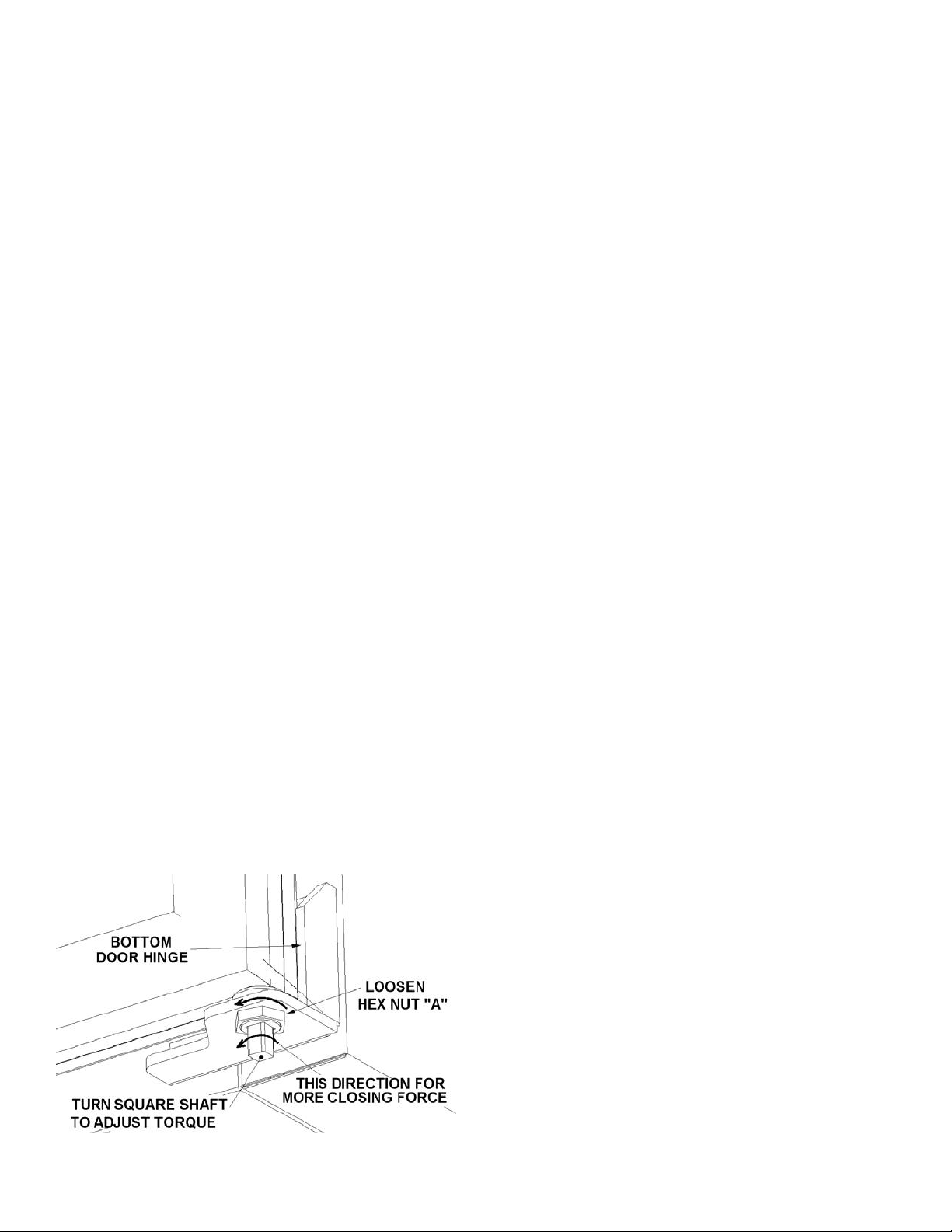
Door Closer Adjustment ( Glass Doors)
Loosen Nut "A" and turn the square shaft to increase or
decrease the torsion rod tension to the desired torque.
Turn the square shaft towards door handle to increase
torque; then tighten Nut "A" to lock.
The door should be set to swing smoothly and should
not slam. Also the door should self-close when opened
only a couple. of inches
Removing Outer Doors (Solid Doors)
If the assembled cabinet is too wide to move through narrow
doorways, the cabinet doors can be removed as follows:
1 )Open the door 180°and support the outer edge.
Remove the screws in the upper hinge at the cabinet,
leaving the hinge attached to the door. Lift and
remove from lower hinge pin. CAUTION: The upper
hinge cam is under significant spring tension. Leave
the hinge in the open position (KEEP HANDS
CLEAR)
2) After legs are on and the cabinet is in final position,
set the doors back on the hinge pins.
Energy Conservation Measures
These cabinets are designed for efficiency with heavy
foam insulation. However, there are things that the user
can do to maintain the cabinet in operating condition.
1) Do not operate the cabinet any colder than necessary
to maintain safe, product storage temperatures.
2) Make sure the cabinet is located to prevent direct
exposure to sunlight, air ducts, etc.
3) Keep the doors closed except for normal use. Inspect
the doors often to see that they self-close and that the
4) Do not overstock the product in the cabinet which will
block normal air flow.
5)Keep the condenser coil clean. The coils should be
inspected at least twice a year.
6) Have at least annual inspections by a qualified service
company to see that the fan motors are functioning
properly and that the refrigerant charge is correct.
7) These cabinets operate more efficiently in a cooler
ambient than in a "hot ambient. Try to maintain an
ambient below 80°F (27°C) and 65% RI-I. for maxi-
mum efficiency.
ROUTINE MAINTENANCE
Cleaning the Interior
Wash the inside surface of the storage one tablespoon
of baking soda per quart of water.) Rinse thoroughly
with clean, warm water and wipe dry. The procedure
can also be used for cleaning the door gasket. Be sure
the power is turned off before cleaning.
Cleaning the Exterior
Wipe the cabinet exterior occasionally with a cloth
damp-ened in mild detergent water, rinse and wipe dry
with a soft cloth. Do not use abrasive or caustic
cleaners or scouring pads.
Cleaning the Condenser
Clean the condenser periodically by brushing the coil with
a soft brush and/or using a vacuum cleaner with a brush
attachment. Be sure that the power is disconnected

6
before cleaning. The condenser fan must be off while
cleaning for safety and to prevent loosened debris from
being drawn further into the coil. Be sure that dirt, dust and
collection of other debris does not build up to a point where
air circulation through the condenser is restricted.
Cleaning the Condensate Pan (Heated)
Caution: De-energize the unit prior to cleaning
heated condensate pans by unplugging the unit
Caution: The heating element used to vaporize the
water in the pan can get quite hot. After unplugging
the unit, allow 10 minutes for it to cool prior to
removing the pan.
The pan is located on the bottom of the cabinet.
Removing the screw that holds the cover over the
electrical plug, unplug the condensate heater and slide
the pan forward to remove it from the cabinet.
Remove and clean all deposits that have built up in the
pan. Take care when replacing the pan to insure that it
is properly placed under the evaporator drain tube that
empties into it. High traffic or humidity may increase the
requirements for servicing this pan.

7
INSTRUCTIONS FOR THE DANFOSS DIGITAL THERMOSTAT / CONTROL
Changing the Set Point
Manual Defrost
Occasionally, the user may need to over-ride the automatic defrost system. This can occur if the evaporator
becomes abnormally frost bound due to excessive humidity or a failure to close the door fully.
To initiate a defrost manually press and hold the lower button for 4 seconds
Note: For all units with top mounted compressors, the thermostat is located directly on the top front panel, for bottom
mount units, the visible control unit is a temperature/status display only. On these units the lower panel must be removed
to access the thermostat. Be careful when removing the panel not to impart too much force on the display cable

8
Control overview, Parameters and Theory of Operation
This unit is equipped with a sophisticated, microprocessor based, digital electronic control. All of the temperature and
defrost functions are controlled by use of a subset of a broad range of the control’s capabilities. Global Refrigeration has
preconfigured this control for optimal performance using the operating parameters listed below. It is highly recommended
that these parameters (other than set point temperature) be left at their Global Refrigeration factory settings. In the event
of a control failure, Global Refrigeration recommends that the replacement control be sourced from us, as our factory
replacement part will be preconfigured for the specific model required. In a service emergency, a Danfoss replacement
control of the same type and model can be used, but it must be installed as the original and programmed with the values
in the table below. All Danfoss parameters not shown are left at the Danfoss default values.
CAUTION: It is essential that control replacement is only done by trained service professionals; non - standard
program parameters may result in serious machine failures and may void the unit or compressor warranty.
Theory of operation: Danfoss controls for Global freezers are equipped with two temperature sensors; a cavity sensor
connected to the S4 input and a defrost sensor connected to the S5 input. It is configured for a time interval initiated /
temperature terminated defrost cycle.
The evaporator fan(s) are configured for continuous operation with the exception that they will de-energize via the
controller’s fan relay during defrost or by the door switch(s) if a door is opened. As temperature rises in the cabinet up to
the set point temperature plus the differential, the compressor control relay will energize, powering the compressor
contactor and the compressor will run. As the temperature falls to the set point, the control will de-energize the
compressor relay. After 8 hours of operation (or other interval specified in param. d03) the unit will initiate a defrost cyc le .
Upon initiation of the of the defrost cycle, the compressor and evaporator fans will de-energize. The control will close the
defrost heater relay and the defrost heater will start heating the bottom of the evaporator coil. As frost melts away, the
temperature of the evaporator outlet tube, (where the defrost temperature sensor is located) will warm. When the defrost
sensor rises above it’s set point temperature of 35°F (param. d02) the defrost heaters will de-energize and the
compressor will be energized. If the defrost sensor fails to reach it’s stop temperature the control will invoke a timed
termination after 35minutes of defrost time (param. d04). Note that the evaporator fans will not resume operation at the
same time as the compressor. The evaporator fans will remain off for 15 minutes (param. d07) or until the defrost
sensor’s temperature declines to 10°F (d08); whichever comes first.
Parameter description.
Danfoss
ULG30BS
T30LSP
T30HSP
T30MSP
Units
Note: parameters not shown are left
Parameter
ULG50BC
T50LSP
T50HSQL
T50MSP
at their Danfoss factory default
Number
ULG80BC
T80LSP
T50HSQHP
T80MSP
T30LGP
settings
T50LGP
T80LGP
Differential
r01
7
7
7
7
°
F
Maximum Set Point setting
r02
+20
0
0
+50
°
F
Minimum Set Point setting
r03
- 20
- 30
- 40
+ 35
°
F
Temperature Units (°C/°F)
r05
F
F
F
F
Control Operating mode*
r12
1
1
1
1
0 = STOP, 1 = RUN, ‐1 = Manual
Defrost method
d01
1
1
1
0
0=None, 1= Electric, 2=Gas, 3 = BRINE
Defrost stop temperature
d02
38
38
38
38
°
F
Interval Between Defrost Cycles
d03
12
12
12
12
Hours
Maximum Length of Defrost Cycle
d04
35
35
35
35
Minutes
Delay for Fan Restart after Defrost
d07
15
15
15
15
Minutes
Fan (Re)start temperature
d08
10
10
10
10
°
F
Fan run during defrost 1 = yes, 0= NO
d09
0
0
0
0
Defrost sensor 0 = time, 1 = S5, 2=S4
d10
1
1
1
0
*- This parameter must be set to 1 for control to function

9
USER SERVICE DIAGNOSTICS:
Items to check prior to calling a service technician
Closer spring needs adjustment
See section on Door Adjustment in Start-up
section
Door fail to self close
Cabinet Un-level
Level cabinet using leg adjustment or shims
(Glass doors only)
Door closer spring broken, gasket failure
Request service, provide service agent with
unit’s model & serial no. for parts requisition
Confirm temperature setting of electronic
See instructions on Changing the Set point
control
Door gaskets loose, torn, or ineffective due
Clean or de-ice as needed or request service for
to ice or residue
gasket replacement
Cabinet environment too warm
Insure that room is below 80°, meets minimum
clearance requirements and unit is not subject to
heat from adjacent appliances.
Dirty Condenser coil
See Routine Maintenance for coil cleaning
Cabinet will not hold
instructions
temperature and / or runs
continuously
Evaporator “Frost bound” (incomplete
Attempt one or two manual defrost cycles to see
defrost cycles)
if normal operation resumes. If not, high
humidity/door cycles may require additional
defrost periods. Failure to defrost may also
indicate bad heater, door gasket, control or
setting; requiring professional service.
Refrigeration system capacity low due to
Professional service required; provide service
defective component or refrigerant charge
agent with unit’s model & serial no. at time of
service request
Compressor starting intermittently or
Professional service required;
shutting off by overload protector
Supply circuit inadequate, defective compr. start
components, crank case regulator inoperative
Cabinet too cold
-Thermostat incorrectly set
-See instructions on Changing the Set point
-Defective sensor
-Sensor: Professional service required
Cabinet will not cool at all,
Probable service level problem
Request service, provide service agent with
but lights, fans and/or
unit’s model & serial no. for parts requisition
control appear to function
Cabinet will not cool at all,
Probable loss of power
-Check to see that unit is plugged in,
-Check supply circuit power (fuse or circuit
controls, lights and fans all
breaker good).
inoperative
-Power switch on unit is ON
Light switch off, blown fuse.
-Turn on switch, glass door models have a light
All lights inoperative.
switch inside the cabinet on the lamp channel.
-All models have a fuse located in the electrical
enclosure (caution: fuse replacement may
require professional service)
LED fixture poorly seated in socket LED
-Reinstall fixture in sockets.
Some lights inoperative
light fixture defective,
-Defective: Request service, provide service
agent with unit’s model & serial no. for parts
Requisition

10
-Compressor shipping strap still installed
-Cut & remove strap.
-Unit unlevel or on irregular surface,
-Level or support unit, silicon seal base to floor
Unit Noisy
-Service level problems: Refrigerant flood
-Request professional service
back, fan blade contact, incidental
component contact, compressor feet too
tight, loose fasteners, defective compressor
or components
This manual suits for next models
15
Table of contents
Other Global Refrigeration Merchandiser manuals
Popular Merchandiser manuals by other brands

Alto-Shaam
Alto-Shaam HSM-24/5S Service manual

Tefcold
Tefcold SCU1375CP datasheet

Alto-Shaam
Alto-Shaam HALO HEAT 750-GDU Installation operation & maintenance

Turboair
Turboair TGM-22RVB Installation and operation manual

Turboair
Turboair TCB-5R Installation and operation manual

Hillphoenix
Hillphoenix JNRBHSA Owner's installation & operations manual

Hussmann
Hussmann IMPACT D6L datasheet

True
True G4SM-23-RGS Specifications

Structural Concepts
Structural Concepts Impulse Series Installation & operating manual

Hussmann
Hussmann WDCHI Installation & operation manual

Hatco
Hatco HZMH Series Installation and operating manual

Hoshizaki
Hoshizaki KD-90C parts list