Global Specialties PB-507 User manual

1
PB-507
Advanced Analog & Digital
Electronic Design Workstation
Instruction Manual
Revision: 2/2014

2
1 FEATURES & APPLICATIONS
The PB-507 Advanced Analog & Digital Electronic Design Workstation is a
versatile electronics trainer used in all levels of electronics instruction and design.
The PB-507 enables the designing of digital and analog circuits in a fun, simple,
easy-to-visualize manner. Utilizing the PB-507, students will learn valuable
hands-on breadboarding techniques and build a solid foundation in circuit
experimentation, construction and analysis. Making it easy for novices to learn
series and parallel circuits, experienced designers also find the PB-507 an
invaluable instrument, providing a reliable platform for the most advanced and
demanding design applications like multi-stage microcomputer circuits.
The PB-507 Trainer contains the following modules:
•DC Power Supplies
•AC Power Supplies
•Function Generator
•Pulse Generator
•Frequency Counter
•Logic Indicators
•Logic Probe
•Hex to 7 Segments Decoder
•Debounced pushbuttons
•Logic switches
•SPDT switches
•BNC connectors
•Potentiometers
•Speaker

3
2 ABOUT GLOBAL SPECIALTIES
Since 1973, Global Specialties has been the recognized leader in innovative
electronics training solutions for education and industry. Basing its product
offerings on the concept of Education Through Application, Global Specialties
believes that relevant scientific and technical education is best when it permits
students to learn by doing.
Global Specialties’ prototyping and trainer systems set the worldwide standard
for reliability, durability and long life, designed to take the sustained use of
educational, research and product testing environments. Global Specialties’ test
& measurement instruments continue to set high standards in quality and
innovation with power supplies, function generators, digital multimeters and logic
analysis products that support its training and prototyping offerings.
A leader in the development of integrated teaching systems, Global Specialties
offers completely packaged courses including everything required for effective
instruction. Comprehensive textbooks, laboratory manuals and instructor guides
have been written in a comfortable, non-intimidating style by experienced
professional educators, specifically for use with our equipment. Each course is
designed to make selections appropriate for a variety of educational levels and
course goals. These systems have found success in secondary schools,
technical schools, universities, and labs throughout the world.
Global Specialties' products are available from electronics distributors worldwide.
Please visit globalspecialties.com to explore the many options available for the
PB-507, such as courseware, pre-formed jumper wire kits, test probes and
prototyping accessories.

4
TABLE OF CONTENTS
1FEATURES & APPLICATIONS ......................................................................2
2ABOUT GLOBAL SPECIALTIES ...................................................................3
3SPECIFICATIONS...........................................................................................5
4INTRODUCTION .............................................................................................6
5START UP .......................................................................................................7
6DESCRIPTION OF INDIVIDUAL FEATURES ................................................8
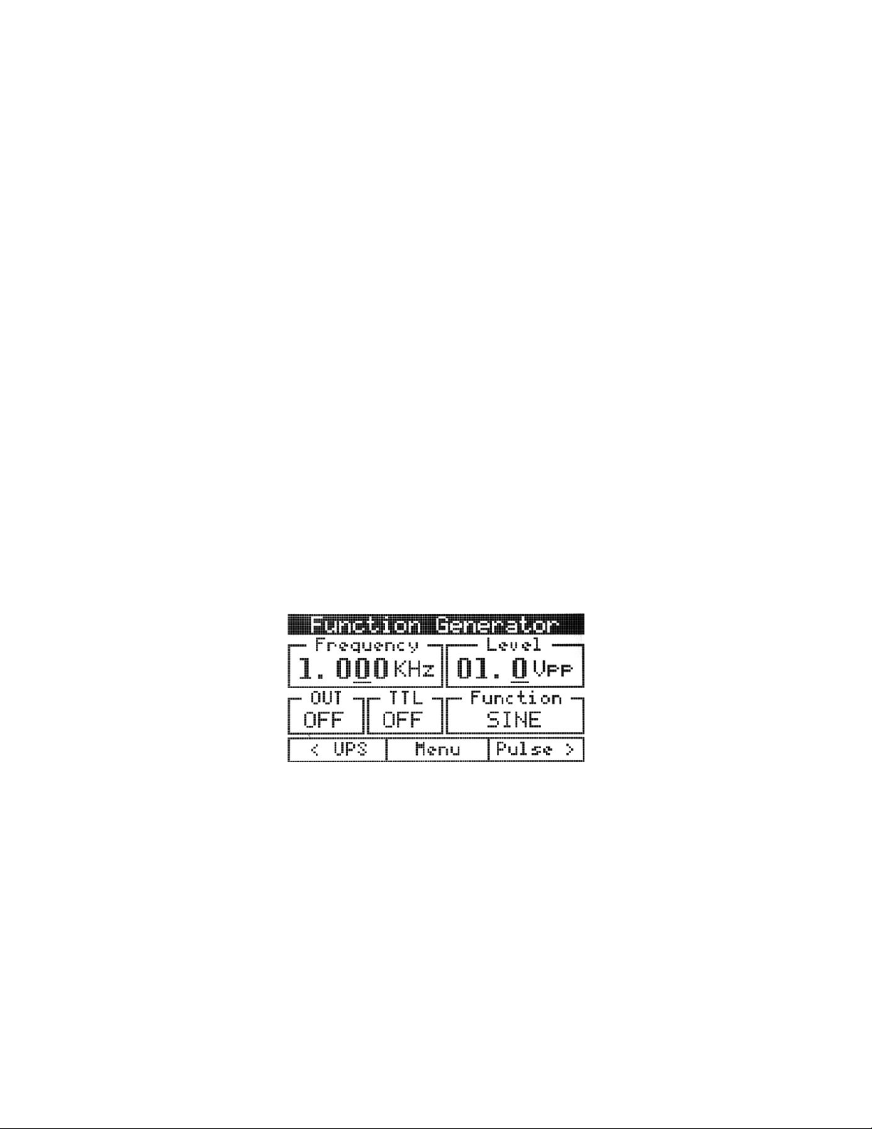
6.1 Function Generator ......................................................................................................... 9
6.2 Pulse Generator............................................................................................................. 12
6.3 Frequency counter ........................................................................................................ 13
6.4 DC Power supplies........................................................................................................ 15
6.5 Debounced pushbuttons .............................................................................................. 16
6.6 Logic switches............................................................................................................... 17
6.7 SPDT switches............................................................................................................... 18
6.8 Logic indicators............................................................................................................. 18
6.9 Logic probe.................................................................................................................... 19
6.10 Seven segment displays............................................................................................... 20
7MENU SYSTEM.............................................................................................21
7.1 Configuration menu ...................................................................................................... 22
7.1.1 Contrast adjustment ................................................................................................. 23
7.1.2 Power-on setting ...................................................................................................... 23
7.1.3 Security .................................................................................................................... 24
7.1.4 Lock or Unlock front-panel keys............................................................................... 26
7.1.5 Page scrolling........................................................................................................... 26
7.1.6 Factory default configuration.................................................................................... 26
7.2 Memory menu ................................................................................................................ 28
7.2.1 State storage............................................................................................................ 28
7.2.2 State name............................................................................................................... 29
7.3 Service menu ................................................................................................................. 30
8CALIBRATION ..............................................................................................30
8.1 Function generator calibration .................................................................................... 30
8.1.1 Step 1....................................................................................................................... 31
8.1.2 Step 2....................................................................................................................... 31
8.1.3 Step 3....................................................................................................................... 32
8.1.4 Step 4....................................................................................................................... 32
8.1.5 Step 5....................................................................................................................... 32
8.1.6 Step 6....................................................................................................................... 33
8.1.7 Step 7....................................................................................................................... 33
8.1.8 Step 8....................................................................................................................... 34
8.1.9 Step 9....................................................................................................................... 34
8.1.10 Step 10..................................................................................................................... 34
8.2 Pulse generator calibration .......................................................................................... 35
8.2.1 Step 1....................................................................................................................... 35
8.2.2 Step 2....................................................................................................................... 36
8.2.3 Step 3....................................................................................................................... 36
8.2.4 Step 4....................................................................................................................... 37

5
8.3 DC Power supplies calibration..................................................................................... 37
8.3.1 Step 1....................................................................................................................... 37
8.3.2 Step 2....................................................................................................................... 38
8.3.3 Step 3....................................................................................................................... 38
8.3.4 Step 4....................................................................................................................... 39
9INFO, WARNING, AND ERROR MESSAGES..............................................39
9.1 Info messages ............................................................................................................... 39
9.2 Warning messages........................................................................................................ 40
9.3 Error messages ............................................................................................................. 40
10 COMPUTER INTERFACE .............................................................................41
10.1 Firmware update............................................................................................................ 42
11 SERVICE AND WARRANTY INFORMATION ..............................................43
11.1 WARRANTY.................................................................................................................... 43
3 SPECIFICATIONS
Power
3-wire AC Input with 110V/220V Selector Switch
Power Supplies
Fixed 5VDC @1A
Variable DC - Positive: 0V to +20V @0.5A
Variable DC - Negative: 0V to -20V @0.5A
Fixed AC - 12.6V Center-tapped @ 100mA
Computer Interface
USB Connector with pin-outs available on Main PCB
Function Generator
0.1Hz to 1MHz selectable in 7 ranges
Output Voltage: 0 to + 10V (20Vp-p)
Output Impedance: 600Ω
Output Waveforms: Sine, Square, Triangle, TTL
Pulse Generator
Frequency Range: 1Hz to 1MHz in 6 ranges
Output Output Mode: TTL or CMOS (switch
selectable)
Output Voltage: 0 to 15Vp-p
Frequency Counter
Frequency Range 0 - 1MHz
LCD Display
LCD Display: Reads Volts, Amps & Frequency
7 Segment Display
(2) BCD to 7 Segment Display Circuits
Logic Indicators
9 Red (High) and 8 Green (low) buffered LEDs
Logic Probe

6
TTL/CMOS compatible Logic Probe
Logic Switches
(8) Individual Logic Switches
Speaker
0.25W, 8Ω
Debounced
Pushbuttons
(2) Open Collector Output Pulsers
Switches
(2) Single Pull Double Throw (SPDT)
BNC Connector
(2) BNC Connectors
Potentiometers
1K & 10K Uncommitted
Breadboard
4150 Tie Points, removable
Voltage Distribution
Bus
Tied directly to Power Supply Outputs
Dimensions
5.5” x 16.5” x 12.75” (H x W x D)
Weight
14.5 lbs
Warranty
Limited three-year warranty
Specifications subject to change without notice. Go to
globalspecialties.com for the latest update.
4 INTRODUCTION
The PB-507 Advanced Analog & Digital Electronic Design Workstation, is a
powerful, versatile tool for circuit designers, engineers, engineering technicians,
students, and hobbyists. All digital controls, USB port, and a wide choice of built-
in circuit accessories allow rapid and accurate construction of virtually any type of
analog or digital circuit.
New on the PB-507 is a LCD screen that displays the settings for each of the
modules. Simply touch a control switch on any module, and the LCD switches to
report the settings from that module. Use the USB connection on the back of the
PB-507 and you can control or view the Workstation from a PC. Using this
feature you can project the controls to a large viewing area for an entire
classroom to observe the changes being made.

7
The PB-507 has a powerful 1 MHz bandwidth Function Generator with sine,
triangle, and square wave output for analog circuits. A Pulse Generator operates
like a second, independent Function Generator with the additional feature that
you can modify the duty cycle to any percentage you like. Use the Counter
module to report on the frequency output of your own specially designed circuits.
Choose your power source: 6.3 /12.6V AC power, 5v DC or variable ±20V DC.
Draw power from the typical banana plug connections or simply tie in to the
additional tie-point power supplies above each breadboard bus strip.
The circuit breadboard area includes over 4100 contact points and is flush
mounted with the unit as are most all switches and controls. The breadboard
area is removable for easy replacement or classroom demonstration.
A built-in speaker may be used for analog output. Outputs also include two
debounced pushbutton switches and a bank of eight logic switches. Eight logic
indicators may be used to display high and low logic levels. A built-in logic probe
is useful in circuit troubleshooting and a hexa 7 segment LED display may be
used in circuit designs.
Two built-in potentiometers and two SPDT switches are provided for circuit
control and adjustment. Connections to external test equipment or a signal
source may be made using the two BNC connectors.
The PB-507 eliminates the clutter and confusion that often results when
constructing sophisticated circuits. Alligator clips and similar connectors are
seldom needed. Sockets on the PB-507 allow insertion of components of wires of
up to 20 gauge.
The PB-507 is designed to withstand the toughest treatment. It is constructed
with the highest quality components available. Most components including the
breadboard are flush with the surface giving greater protection. Reliable digital
circuitry is used throughout.
A detailed panel layout and description of the PB-507 is given in the section
"Description of Individual Features".
5 START UP
At power on the PB-507 Trainer displays the Global Specialties logo and the
“Initializing…” message. Initialization takes a few seconds, after which the current
configuration (“Loading default config…” or “Loading last state…”) and an
information message about the system errors is displayed:

8
Figure 1
A power-on self test occurs automatically whenever you turn on the PB-507
Trainer. If the self test passed, the “No errors found” message is displayed on the
bottom of the screen. If the self test failed, the “Errors found” message is
displayed on the bottom of the screen. You can view the error message queue
anytime by selecting the ServiceError log option from menu.
After the power up sequence one of the following four panels is loaded: Function
Generator, Pulse Generator, Frequency Counter or DC Power Supplies. You can
navigate through these four panels using the soft keys below the display. If PB-
507 is set to load the last saved state, then the last panel used before powering
off the device will be loaded at next power on. If PB-507 is set to load the default
configuration, then the Function generator panel will be loaded.
Three soft keys are located below the display. The function of each button is
always shown on the bottom of the screen. These buttons are used to navigate
through panels and menus.
6 DESCRIPTION OF INDIVIDUAL FEATURES
In order to properly use the full capabilities of the PB-507 it is highly
recommended that the user become familiar with the panel layout and the
features of the components.

9
6.1 Function Generator
Front-panel controls
Figure 2 shows the Function Generator and Pulse Generator controls on the front
panel of the trainer.
Figure 2

10
Frequency knob: changes the value of frequency between 0.1 Hz and
1.000MHz.
Level knob: changes the value of the level in the range between 0.1 Vpp and
10.0 Vpp into 600 Ωload (0.2 to 20.0 Vpp in open circuit).
buttons: move the cursor from one digit to another inside a field or to the
next field.
Up and Down buttons: change the frequency range. 7 frequency ranges are
available.
Function button: changes the waveform of the output signal. The waveform can
be sine, triangle or square.
Out On/Off button: enables or disables the output signal (OUT) for the function
generator. When OUT is enabled, the OUT LED is turned on, and when OUT is
disabled, the OUT LED is turned off.
TTL On/Off button: enables or disables the TTL signal for the function
generator. When TTL is enabled, the TTL LED is turned on, and when TTL is
disabled, the TTL LED is turned off.
Display Area and Screen Interface
Figure 3 shows the trainer’s screen displaying the function generator panel.
Figure 3
Changing the parameters
Frequency
In order to cover the entire frequency range from 0.1 Hz to 1.000 MHz, 7
frequency ranges are used. Range Up and Range Down buttons change the
range. The 7 ranges are defined as follows:
•0.1 Hz - 0.9 Hz
•1.0 Hz - 9.9 Hz
•10.0 Hz - 99. 9 Hz

11
•100.0 Hz - 999.9 Hz
•1.000 KHz – 9.999 KHz
•10.00 KHz – 99.99 KHz
•100.0 KHz – 999.9 KHz
•1 MHz.
By pressing Range Up button the frequency value will be multiplied by 10 and by
pressing Range Down button the frequency value will be divided by 10. The
displayed number and the cursor position will not change.
For example, if 100.0 Hz is set and Range Up is pressed several times, the
following sequence will be achieved: 100.0 Hz 1.000 KHz 10.00 KHz
100.0 KHz 1.000 MHz.
Turn the Frequency knob to change the frequency value. The underscored digit
will be changed and it will be displayed in white type inside a black box indicating
that the frequency field became active:
Use the arrow keys to move the selection. If the cursor is moved outside of the
Frequency field limits the Level field will become active. If the cursor is moved
further, the frequency field will be selected again and so on. Selection of the
active field can be done in two ways:
•Automatically by turning the appropriate knob (Frequency or Level), or
•Moving the cursor from one field to another.
If the frequency value is at the end of a range and the frequency knob is turned,
frequency value will switch to the next range:
•Increasing the frequency value, the cursor is moved one step to the right
(if it is possible). For example: 90.00 KHz --> 100.0 KHz or 900.0 KHz -->
1.000 MHz,
•Decreasing the frequency value, the cursor is moved one step to the left (if
it is possible). For example: 100.0 KHz --> 90.00 KHz or 1.000MHz -->
900.0 KHz.
Level
Level is changed in the same manner as frequency. The Level knob changes the
amplitude of the output signal. The arrow keys can be used to change the digit
selection when the Level field is active. If the cursor is moved outside of the
Level field limits, the Frequency field will become active.
The level field displays the value corresponding to 600 Ωnominal load.

12
Waveform
The Function button can be used to select the output function in the following
order: - Sine - Triangle - Square - Sine - The current waveform is displayed on
the screen.
Enabling the output signal
Pressing Function On/Off button enables/disables the output signal. In order to
enable/disable the TTL output, the TTL button must be pressed. The
corresponding LED is turned on. Output and TTL states are displayed on the
screen. See Figure 3.
6.2 Pulse Generator
Front-panel controls
Figure 2 shows the Pulse Generator controls on the front panel of the trainer.
Frequency knob: changes the value of frequency between 0.1 Hz and
1.000MHz.
Level knob: changes the value of the level in the range between 1.0 Vpp and
15.0 Vpp in open circuit.
Duty cycle knob: changes the value of duty cycle in a percentage between 10%
and 90%.
buttons: move the cursor from one digit to another inside a field or to the
next field.
Up and Down buttons: change the frequency range. 7 frequency ranges are
available.
CMOS button: enables or disables the CMOS signal for the pulse generator.
When CMOS is enabled, the CMOS LED is turned on, and when CMOS is
disabled, the CMOS led is turned off.
TTL button: enables or disables the TTL signal for the pulse generator. When
TTL is enabled, the TTL LED is turned on, and when TTL is disabled, the TTL led
is turned off.
Display Area and Screen Interface
Figure 4 shows the trainer’s screen displaying the pulse generator panel.

13
Figure 4
Changing the parameters
Frequency, Level
See description from function generator. The same rules are applied for the pulse
generator too. Level field displays the CMOS level of the pulse generator signal.
The value with no load is displayed.
Duty cycle
The duty knob changes the duty cycle of the output signal between 10% and
90%, minimum step being 1%. The arrow keys can be used to change the digit
selection when the Duty cycle field is active. If the cursor is moved outside of the
Duty cycle field limits, the Frequency or the Level fields will become active.
Enabling the output signal
Pressing CMOS button enables/disables the CMOS signal. In order to
enable/disable the TTL output, the TTL button must be pressed. The
corresponding LED is turned on. CMOS and TTL states are displayed on the
screen. See Figure 4.
6.3 Frequency counter
Front-panel controls
Figure 5 shows the Frequency Counter controls on the front panel of the trainer.

14
Figure 5
Unipolar/Bipolar button: The type of the input signal can be changed anytime
by pressing the Unipolar/Bipolar button.
Description
The Frequency counter module can measure the frequency of bipolar or unipolar
signals. The term unipolar indicates that the signal swings from zero (ground) or
a positive voltage to a higher voltage, and bipolar indicates that the signal swings
above and below zero (ground).
If Counter mode (configured in menu) is set to “Automatic”, the input signal type
is detected automatically, but the first measurement may take more time in this
case.
The measurement of low frequency signals requires a long time (for example, to
measure Fin = 0.2Hz, is required at least 10s for the first measurement).
The Frequency counter operation is signaled by three LEDs:
•No signal: signal not detected
•Done: a valid frequency is displayed on the screen. The first measurement
is not precise.
•Counting: a new measurement is in progress.
Display Area and Screen Interface
Figure 6 shows the trainer’s screen displaying the Frequency counter panel.

15
Figure 6
The following information is displayed in the counter panel:
•The measured frequency and the corresponding period
•The type of the input signal
•Counter mode: AUTO or MAN
•The current state of the counter: NO SIGNAL or COUNTING.
6.4 DC Power supplies
Front-panel controls
Figure 7 shows the DC Power Supplies controls on the front panel of the trainer.
Figure 7
Positive voltage knob: changes the value of the +V DC power supply between
0V and 20V.
Negative voltage knob: changes the value of the -V DC power supply between -
20V and 0V.
buttons: move the cursor from one digit to another inside a field or to the
next field.
Display Area and Screen Interface
Figure 8 shows the trainer’s screen displaying the DC power supplies panel.

16
Figure 8
Changing the parameters
+V, -V
Turn the +V knob to change the +V value. Turn the –V knob to change the –V
value. The underscored digit will be changed and it will be displayed in white type
inside a black box indicating the active field.
Use the arrow keys to move the selection. If the cursor is moved outside of +V
field limits, the –V field will become active and vice versa. Selection of the active
field can be done in two ways:
•Automatically, by turning the appropriate knob (+V or –V) or
•Moving the cursor from one field to another.
Note: When +V or –V is modified by the user, the programmed voltages are
displayed for about 3 seconds.
Monitoring the output voltages
•+V, -V and the 5V voltages are continuously measured. While +V, -V and
5V voltages are between the specified tolerance the corresponding LEDs
will light green.
•The fixed 5V voltage measurement is displayed continuously on the
screen. If the output accuracy is out of the specified tolerance (± 200mV),
the corresponding LED will light red.
•The +V and –V voltage measurements are continuously compared to the
programmed values. If the output accuracy is out of the specified
tolerance (± 100mV), the corresponding LED will light red.
6.5 Debounced pushbuttons
Front-panel controls
Figure 9 shows the Debounced pushbuttons controls on the front panel of the
trainer.

17
Figure 9
Description
PB-507 provides two open-collector output pulsers, each with 1 normally-open
(NO) and 1 normally-closed (NC) output. When the pushbutton is released, the
circuit is in NC state, and when the pushbutton is pressed, the circuit is in NO
state. The corresponding green led will light.
6.6 Logic switches
Front-panel controls
Figure 10 shows the Logic switches controls on the front panel of the trainer.

18
Figure 10
Description
PB-507 provides 8 logic debounced outputs with 2 user selectable logic families:
CMOS and TTL. Each of the logic switches can be switched separately between
logic high (red) and logic low (green) by pressing the buttons S7…S0. When
CMOS is selected, the high level is determined by the +V voltage set for the DC
power supply.
The logic family (TTL or CMOS) can be selected using the TTL/CMOS button.
6.7 SPDT switches
Front-panel controls
Figure 11 shows the SPDT switches controls on the front panel of the trainer.
Figure 11
Description
Two single pole, double throw (SPDT) switches are provided for general switching
functions. Two LEDs for each switch are used to signal the current state of the
switch.
6.8 Logic indicators
Front-panel controls
Figure 12 shows the Logic indicators controls on the front panel of the trainer.

19
Figure 12
Description
•Eight bicolor LEDs (b7…b0) are used to indicate logic high (red) or low
(green) for eight digital inputs.
•The TTL or CMOS input switching levels can be selected by pressing
button TTL/CMOS. The High and Low thresholds for CMOS depend on
the positive voltage set in the DC Power supplies module.
•The LEDs will light red when the inputs are 2.0V or higher when TTL is
selected, or 70% of the +V voltage or higher when CMOS is selected.
•The LEDs will light green when inputs are 0.8V or less when TTL is
selected, or 30% of the +V voltage or less when CMOS is selected.
•In the case of an unconnected input or an input not at valid logic level the
corresponding LED will turn off.
•If CMOS input is selected and +V voltage is less then 1V, the Logic
indicators module will not work. In this case the CMOS LED will flash.
6.9 Logic probe
Front-panel controls
Figure 13 shows the Logic probe controls on the front panel of the trainer.
Figure 13
Description
•The Logic probe is a logic troubleshooting instrument that detects Logic
High (red LED), Logic Low (green LED) and single shot events (yellow
LED).
•Two operation modes are provided: Memory or Pulse. The operation
mode can be set by pressing the MEM/PULSE button.
•PULSE mode is the normal operation mode for pulse and level detection.

20
•MEMORY mode detects single shot events and holds indication until
Pulse/Mem switch is toggled.
•The TTL or CMOS input switching levels can be selected by pressing
button TTL/CMOS.
•The High and Low thresholds for CMOS depend on the positive voltage
set in the DC Power supplies module. A Logic High level will be detected
when the inputs are 2.0V or higher when TTL is selected, or 70% of the
+V voltage or higher when CMOS is selected. A Logic Low level will be
detected when inputs are 0.8V or less when TTL is selected, or 30% of the
+V voltage or less when CMOS is selected.
•If CMOS input is selected, the Logic probe module will not work if +V
voltage is less then 1V. In this case the CMOS led will flash.
6.10Seven segment displays
Front-panel controls
Figure 14 shows the Hex to 7 segment LED display module on the front panel of
the trainer.
Figure 14
Description
The Hex to 7 segment decoder can display all hexadecimal characters (0-9 and
A-F) on the seven segment display. The Hex to 7 segment decoder uses an 8 bit
input to display the characters on two 7 segment displays.
The following table shows the characters displayed on 7 segment display:
Input (S7…S4 or
S3…S0)
7 segment display
Table of contents
Other Global Specialties Desktop manuals