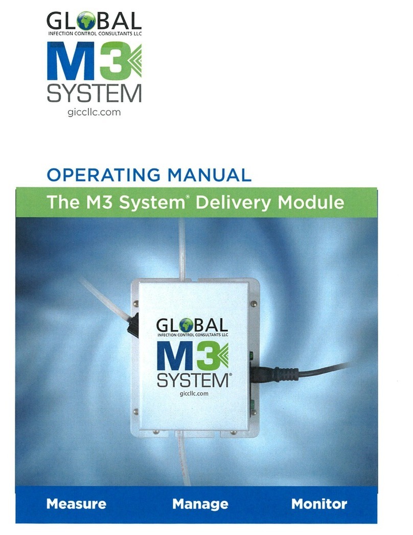
Global M3 SYSTEM User manual

®
INFECTION CONTROL CONSULTANTS LLC
OPERATING MANUAL
The M3 System® Delivery Module
giccllc.com
Measure Manage Monitor

®
INFECTION CONTROL CONSULTANTS LLC
giccllc.com
PROVIDING A SAFE AND HEALTHY INDOOR ENVIRONMENT

General Safety Guidelines 4
5
6
7
9
12
16
18
20
23
Purpose of Use and Safety
Environmental Safety
Transportation and Storage
Installation
Piping Connections
Priming
Troubleshooting
Maintenance
Warranty
Table of
Contents

The M3 System® Delivery Module4
These operating instructions contain safety
information that, if ignored, can endanger life or
result in serious injury.
Read these instructions carefully before use and
keep them for future reference.
Version: R1
General Safety Guidelines
Operating, installing, or maintaining the unit in any
way that is not covered in this manual could cause
death, serious personal injury, or damage to the
equipment.
This manual uses the following safety message icons:
Danger! Warning!
Indicates a hazardous situation which, if not avoided,
could result in death or serious injury.
Important!
A practice not related to personal injury or additional
information.

5The M3 System® Delivery Module
PURPOSE OF USE AND SAFETY
The M3 System® Delivery Module is intended for
fluid dispersion of Path-Away Anti-Pathogenic
Aerosol Solution® or an alternate approved by GICC.
• Do not use in explosive area
• Do not use with flammable chemicals
• Do not use with radioactive chemicals
• Use only after a proper installation
Before any operation:
• Always read product Material Safety Data Sheet (MSDS)
•Always wear protective clothing
•Always discharge the liquid end before servicing the pump
•This unit shall never be used with hazardous or unknown chemicals
Use the delivery module in accordance with the data and
specifications printed on the label.
Do not modify or use in a manner inconsistent with the provisions of
the operating manual.
Keep the delivery module protected from sun and water. Avoid water
splashes.
In emergencies, the delivery module should be switched o
immediately. Disconnect the power cable from the power supply.
When installing, always observe national regulations.
Manufacturer is not liable for any unauthorized use or misuse of this
product that may cause injury, or damage to persons or materials.
The delivery module must be accessible at all times for both
operating and servicing. Access must not be obstructed in any way.
Adequate measures shall be taken to prevent cross connection of
product with any chemicals.
Pump and accessories must be serviced and repaired by qualified
and authorized personnel only.
Risk of electric shock - This pump is supplied with a grounding
conductor and grounding type attachment plug. To reduce the risk
of electric shock, be certain that it is connected only to properly
grounded, grounding-type receptacle.
CAUTION - This Pump Has Been Evaluated for Use With Path-Away
Anti-Pathogenic Aerosol Solution only.

The M3 System® Delivery Module6
ENVIRONMENTAL SAFETY
Spare parts For spare parts orders or any other communication,
refer to the pump’s label. The serial number can be
used to uniquely identify the Delivery Module..
THIS DELIVERY MODULE IS TESTED AND
CERTIFIED BY UL FOR MATERIALS SAFETY.
Work area
Always keep the delivery module area clean to avoid and/or
discover emissions.
Recycling guidelines
Always recycle according to these guidelines:
• If the unit or parts are accepted by an authorized recycling
company, then follow local recycling laws and regulations
• If the unit or parts are not accepted by an authorized recycling
company, then return them to the nearest representative
Waste and emissions regulations
Observe these safety regulations regarding waste and emissions:
• Dispose appropriately of all waste
• Handle and dispose of the dosed product in compliance with
applicable environmental regulations
• Clean up all spills in accordance with safety and environmental
procedures
• Report all environmental emissions to the appropriate authorities
Label (Example)
Fig. 1. UL label.
*SA6040D85 030621 1209*
Model: SA6040D85
100-120 Vac, 60 Hz, 1.2A, 120 W
Insulaon Class A
Duty Cycle: 6 Seconds
Manufactured Date: xx/xx/20xx
US Patent Pending #62/706,137
CAUTION – This pump has been evaluated for use with Path-Away An-Pathogenic Aerosol Soluon only.
WARNING – Risk of Electric Shock – This Pump Has Not Been Invesgated For Use In Swimming Pool or
Marine Areas. To reduce electric shock, connect only to a properly grounded, grounding type receptacle.
Acceptable For Indoor Use Only.
Nonsubmersible Pump.
UL 60730-1
UL778
CAN/CSA-E60730-1
CSA C22.2 No. 108
Serial Number: xxxxxxxxxxxx
M3 System® Delivery Module
www.m3systemprotecon.com
Global Infecon Control Consultants LLC.
Technology property of GICC LLC

7The M3 System® Delivery Module
TRANSPORTATION AND STORAGE
A non-suitable transportation or storage container can cause
damages.
Use original box to pack the delivery module.
Observe storage conditions for transportation.
Although securely packed, always protect the unit against
humidity and avoid direct contact of chemical agents not
acceptable for use or contact with unit.
Before returning the delivery module to the manufacturer for
repair service, drain the product from pump head and rinse.
Do not trash packaging. Use it to return the delivery module.
Transportation and storage temperature: 10 - 50°C (32 - 122°F)
Humidity 95% relative humidity (not condensed)
Included
features QUANTITY CONTENT M3 SYSTEM
n. 1 Main Unit
n. 1 Back Pressure Regulator
w/Nozzle
n. 1 Axial Foot Filter (PVDF)
n. 1 Injection Valve (PVDF)
m 7.6 Delivery Hose
m 2.4 Suction Hose
m 3.0 Discharge Hose
m 1.8 Power Cable
n. 1 Operating Manual

The M3 System® Delivery Module8
Tab. 1. Capacity
FLOW
Model
M3 4.31 4.69 0.00113 0.249 18 7 101.5 4 x 6 4 x 60.001239
min
cc/h
max
I/h
Min
GPH
Max
GPH
pulse
/
min
Maximum
pressure
bar PSI delivery
(PE)
suction
(PE)
Hosescc per
STROKE
Environment temperature•••••••••••••••••• 5-50°C (23-113°F)
Solution temperature •••••••••••••••••••••• 0 - 50°C (32 - 122°F)
Transportation and storage temperature••• 10 - 50°C (32 - 122°F)
Installation class•••••••••••••••••••••••••••• II
Pollution level •••••••••••••••••••••••••••••• 2
Audible noise •••••••••••••••••••••••••••••• 71 dbA
Altitude •••••••••••••••••••••••••••••••••••• 1013 mbar
Dimensions •••••••••••••••••••••••••••••••• 159*128.4*139.1mm
Max installation height ••••••••••••••••••••• 1.5 m

9The M3 System® Delivery Module
INSTALLATION
How to install
M3 System
6 steps to install and start-up the delivery module:
1. Main unit mounting
2. Back pressure regulator mounting
3. Piping connections (hoses, injection valve,
pickup valve, back flow pressure regulator)
4. Wirings
5. Pump priming
6. Start-up
The operator must be aware of safety precautions to prevent physical injury.
Disconnect power supply before you perform
any installation or maintenance tasks. Failure to
disconnect power can result in serious physical
injury.
User health
and safety
equipment
Use safety equipment according to
the company regulations. Use the following
safety equipment within the work area:
• Helmet
• Safety goggles (with side shields)
• Protective shoes
• Protective gloves
The work
area
Observe these regulations and warnings in
the work area:
• Always keep the work area clean
• Pay attention to the risks presented by
outside gas and vapors in the work area
• Avoid all electrical dangers. Pay attention to
the risks of electric shock or arc flash hazards
• Avoid water splashes and direct sun
Power supply
disconnection

The M3 System® Delivery Module10
Fig. 2. Installation overview
Pump
location
Requirements
for product
positioning
Pump must be installed on a stable support
at a max 2.0 m height from tank’s bottom.
Injection point must be higher than tank to
avoid accidental chemical injection.
Install the pump:
• In a safe place and fixed flat surface / wall
to avoid vibration problems
• In an easily accessible place
• In vertical position
Use only hoses compatible with product.
Only use fasteners of the proper size and
material. Replace all corroded fasteners.
Make sure that all fasteners are properly
tightened and that there are no missing
fasteners.
Installation
pump
guidelines
Back pressure regulator Delivery hose Air discharge Purge activation button
Power cable
Suction hose
Pick up valve
Nozzle

11The M3 System® Delivery Module
Overview of
Set-Up Assembly
The main unit has three screw locations for
mounting. The top of the unit has a single screw
location, whereas the bottom of the unit has two
screw locations. Ensure that you are positioning
the unit correctly, with the air discharge hose at
the top, in vertical position. When mounting the
unit, ensure the unit is fastened securely to the
surface, able to withstand weight and vibration.
Fig. 3. Main unit mounting
Single mounting location (top)
Two mounting locations (bottom)

The M3 System® Delivery Module12
Pickup Valve
& Strainer
When connecting the piping, ensure that o-ring
has been placed between threading nut and pick
up valve as shown in Fig. 4.
Pickup valve is assembled with a foot filter (strainer)
that avoids sediment priming problems. Install
pickup valve on the bottom of the tank. (Fig. 5)
PIPING CONNECTIONS
Suction hose
connection
Suction hose should be as short as possible
and installed in vertical position to avoid air
bubbles when suctioning.
Completely unscrew tightening nut from
pump’s head and remove assembling
components: tightening nut, holding ring
and pipe holder.
Assemble as shown in Fig. 6.
Insert hose into pipe holder until it reaches
the bottom. Lock hose on pump’s head by
screwing down the tightening nut.
Fig. 5. Pickup valve & strainer
Suction hose
Pipe holder
Threading nut
Pickup valve
Strainer
Fig. 4. Pickup valve & strainer o-ring installation

13The M3 System® Delivery Module
Pump head /
delivery hose
assembling
procedure
Hand-tighten nuts firmly
Do not use other tools to tighten nuts.
Suction and air discharge valves must be in
vertical position.
Delivery hose must be firmly fixed to avoid
sudden movements that could damage
near objects.
Completely unscrew tightening nut from
pump’s head and remove assembly
components: tightening nut, holding ring
and pipe holder. Assemble as shown in Fig.7.
(page 14)
Insert hose into pipe holder until it reaches
the bottom. Lock hose on pump’s head by
screwing down the tightening nut.
Hand-tighten nuts firmly.
Do not use other tools to tighten nuts.
Connect the other end of the hose to the
injection valve using the same procedure.
Fig. 6. Suction hose assembling
Suction hose
Threading nut
Holding ring
Pipe holder

The M3 System® Delivery Module14
Fig. 7. Delivery hose / pump
head assembling
Fig. 8. Self-venting
pump head
To bleed hose
Delivery hose
Threading nut
Holding ring
Pipe holder
To delivery hose/
back pressure regulator
To suction hose
M3 System
self venting
pump head
connection
Refer to Fig. 8 below for delivery and discharge
hose. Assembling procedures are the same as
described previously.
Suction, delivery and discharge (bleed) valves
are dierent.

15The M3 System® Delivery Module
Screw mounting positions
M3 System
back pressure
regulator
Notes:
Refer to Fig. 9 and Fig. 10 below for mounting
instructions of the back pressure regulator and
nozzle. When connecting the piping, ensure that
the o-ring has been properly installed to avoid
leakage.
Fig. 10. Screw mounting locations
on back pressure regulator
Fig. 9. Piping o-ring installation

The M3 System® Delivery Module16
PRIMING
Warning Pump should be shut-o when there is
no flow.
Never operate any pumping system with a
blocked suction and/or discharge. You must
take all necessary measures to avoid this
condition.
Use safety equipment according to the
company regulations. Use this safety
equipment within the work area:
• Helmet
• Safety goggles (with side shields)
• Protective shoes
• Protective gloves
Pump’s
priming
To prime the pump:
1. Ensure all piping is secure (delivery, suction
and discharge hose).
2. Ensure the pickup valve is fully submersed,
and the bleed hose is also flowing back
into pick-up basin.
3. Plug in the unit and turn on main power
switch.
4. Press and hold prime button for four
seconds to activate prime cycle.
5. Prime cycle will run continuously for
three minutes and nozzle will begin to
disperse within the cycle time (do not stop
the prime cycle early; even if liquid has
started to disperse through the nozzle as
there still could be air discharging through
the air discharge hose).
6. After the prime cycle is complete, the
system will enter “normal operation mode,”
activating 6 seconds per hour.
Safety
equipment

17The M3 System® Delivery Module
Fig. 11. Main unit switches
and indicators
Pump’s wiring / switch / indicators
Back flow pressure regulator adjustment
The back pressure regulator can be adjusted to control the pressure,
thus allowing the flow output from the nozzle. If the unit is not flowing
it could be encountering pressure lock. In this situation, during priming
mode, rotate the adjustment pin counter clockwise until pin is level
with black surface. Once liquid starts to disperse from the nozzle, start
to screw the pin clockwise, this will then raise the pressure and begin
to allow the nozzle to disperse correctly.
Fig. 12 Back pressure regulator
pressure adjustment
Activate / prime
Press once for activation and
press and hold for 4 seconds
to begin Prime Cycle
Clockwise to increase pressure
Counter clockwise to
decrease pressure
Regulator adjustment pin

The M3 System® Delivery Module18
TROUBLESHOOTING
If the problem cannot be solved, please contact after-sales
service or return the delivery module to the manufacturer.
PROBLEM CAUSE REMEDY
Pump does not
start
• Pump not powered
• Protection fuse
• Main board
• Connect to main power source
• Replace fuse
• Replace main board
Pump does
not feed but
solenoid runs
• Foot filter obstruction
• Pump head empty
(suction pipe empty)
• Air bubbles into pump
head or into suction pipe
• Clean the foot filter
• Prime the pump
• Check valves, pipes and fittings
• Adjust the Back Pressure Regulator Pin
• Remove the foot filter from liquid, and
hold the foot filter above the pump
head level.
• Run one cycle of purge with foot filter
placed above the level of pump head.
Once complete, place back into the
liquid, and run a second purge.
Pump does not
feed, solenoid
does not run or
slightly run
• Valves and/or ball valves
blocked
• Injection valve obstruction
• Spray nozzle obstruction
• Clean valves and ball valve. Feed 2-3
liters of water to wash valves and pump
head
• Change valves
• Remove nozzle, soak in water, and then
blow air to discharge any small particles
Repair
service
Before returning the delivery module to the
manufacturer for repair, drain the product from
pump head and rinse it.
Make sure that the product is isolated from
the power supply and cannot be powered by
mistake.

19The M3 System® Delivery Module
Fuse
replacement
procedure
Main board
replacement
procedure
Make sure that the product is isolated from
the power supply and cannot be powered
by mistake.
This procedure should be carried out by
authorized and qualified personnel.
In order to replace main board, follow the
steps below with the listed items:
• A 3x16 screwdriver
• New main board
• Unplug power supply and piping
• Remove screws around base of the main unit
• Pull back cover until it’s completed
separated from main unit
• Remove board
• Completely disconnect wires from main
board and replace it
• Reconnect wires to the main board
• Reassemble the back cover
• Reinsert screws
This procedure should be carried out by
authorized and qualified personnel.
In order to replace fuse, follow the steps below
with the listed items:
• A Flathead screwdriver
• Fuse
• Unplug power supply and piping
• Remove fuse cover near main power switch
• Pull back cover until it’s completely separated
• Locate the fuse and replace with a new one
• Reassemble fuse cover

The M3 System® Delivery Module20
MAINTENANCE
Maintenance
schedule
In order to ensure proper working order as
declared by the manufacturer, this equipment
must be checked at least once a month.
Use safety equipment according to the
manufacturer product regulations.
Use the following safety equipment within the
work area during installation, service and when
handling chemicals:
• Protective mask
• Protective gloves
• Safety goggles
• Ear plugs or ear mus
• Further security device, if necessary
Always disconnect power before you perform
any installation or maintenance tasks. Failure
to disconnect power will result in serious
physical injury.
Installation and maintenance tasks should be
carried out by authorized and qualified personnel
only in accordance with local regulations. Use
original spare parts for repairs.
Operator
protection
Power supply
disconnection
Installation
and
maintenance
Other manuals for M3 SYSTEM
1
Table of contents
Other Global Control Unit manuals
Popular Control Unit manuals by other brands

Victaulic
Victaulic Vic-300 MasterSeal 761 Series Installation and maintenance instructions

aFe Power
aFe Power 77-46101 SCORCHER HD manual

Allen-Bradley
Allen-Bradley 1746-HSTP1 user manual

EMS
EMS ZITON Programming manual

Lutz-Jesco
Lutz-Jesco PENTABLOC operating instructions

Lenz
Lenz Digital Plus XpressNet SET-01/10 Operation manual