Global Right Flyer 40T Mk.II User manual

1
The Right Flyer 40T Mk.II is distributed exclusively by
Global Hobby Distributors
18480 Bandilier Circle Fountain Valley, CA 92728
All contents copyright © 2000, Global Hobby Distributors Version V.1.0 2/00
INSTRUCTIONS FOR FINAL ASSEMBLY

2
TABLE OF CONTENTS
Fuel Tank................................................................16
Stopper Assembly............................................16
Installing the Stopper......................................17
Fuel Tank Installation......................................17
Servo Installation...................................................18
Installing the Fuselage Servos.........................18
Installing the Aileron Servo Tray.....................18
Installing the Aileron Servo.............................19
Throttle Pushrod....................................................20
Installing the Pushrod Wire.............................20
Installing the Servo Connector........................20
Adjusting the Throttle Linkage.......................20
Elevator Pushrod....................................................21
Installing the Control Horn.............................21
Installing the Pushrod......................................21
Adjusting the Elevator Pushrod.......................22
Rudder Pushrod.....................................................22
Installing the Control Horn.............................22
Installing the Pushrod....................................23
Adjusting the Rudder Pushrod........................24
Aileron Linkage....................................................24
Installing the Aileron Linkage.......................24
Adjusting the Aileron Linkage.......................25
Final Assembly......................................................25
Installing the Fuel Lines..................................25
Installing the Switch.......................................26
Installing the Receiver....................................26
Installing the Propeller....................................26
Balancing...............................................................27
Control Throws.......................................................27
Preflight Check.....................................................27
ABC's of Flying....................................................28
Basics of Flight.....................................................28
Glossary of Terms.................................................31
Notes.....................................................................32
Product Evaluation Sheet......................................35
Introduction.............................................................3
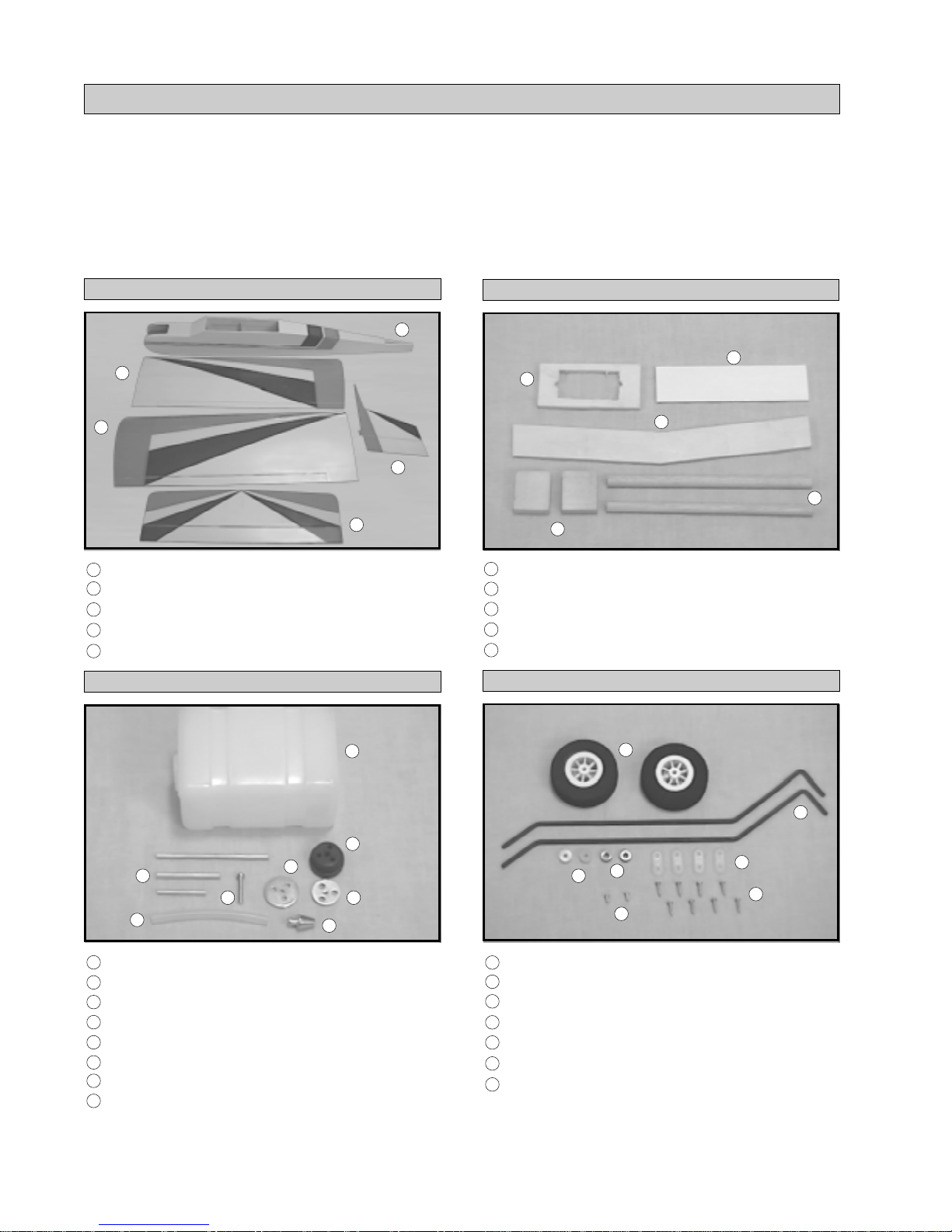
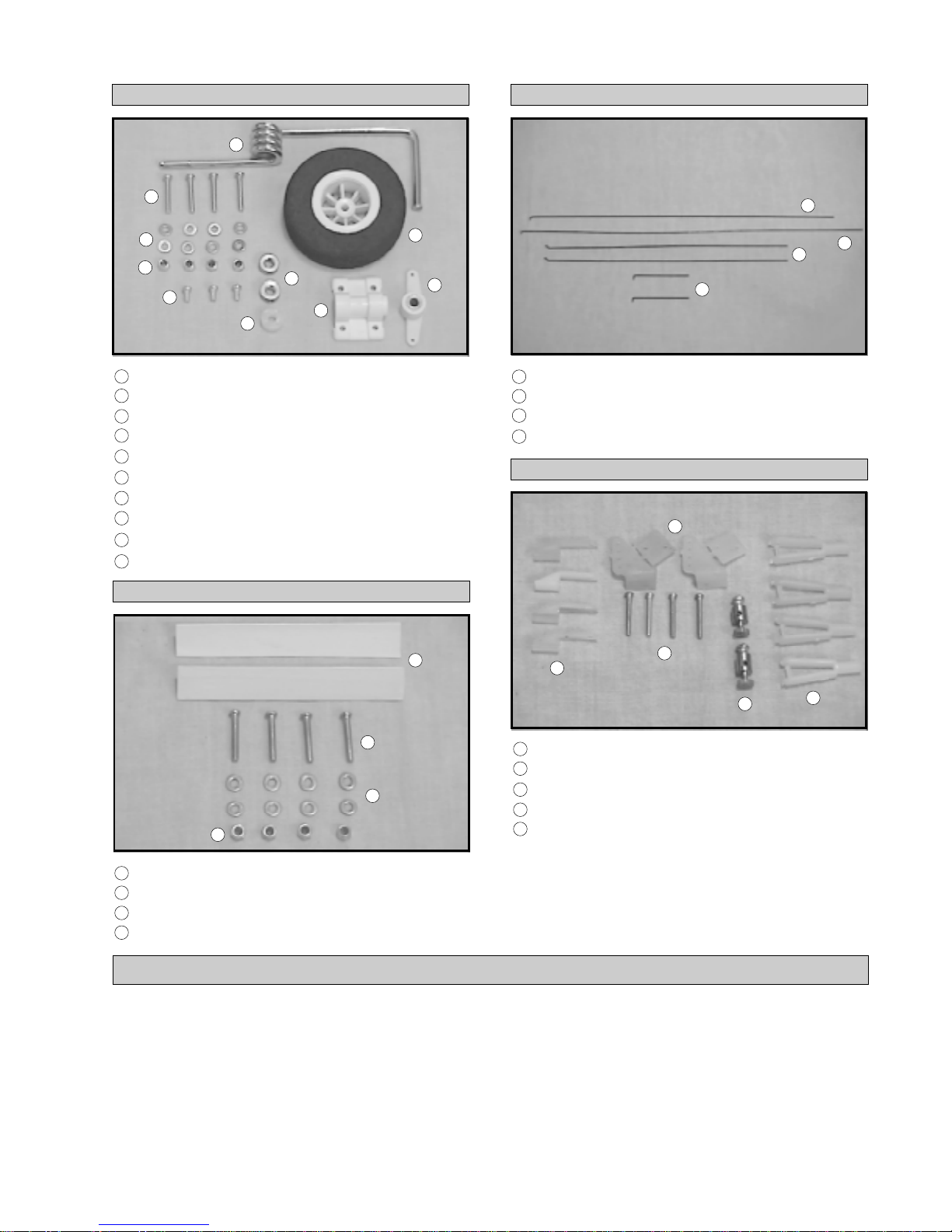
Kit Contents............................................................4
Metric Conversion Chart........................................5
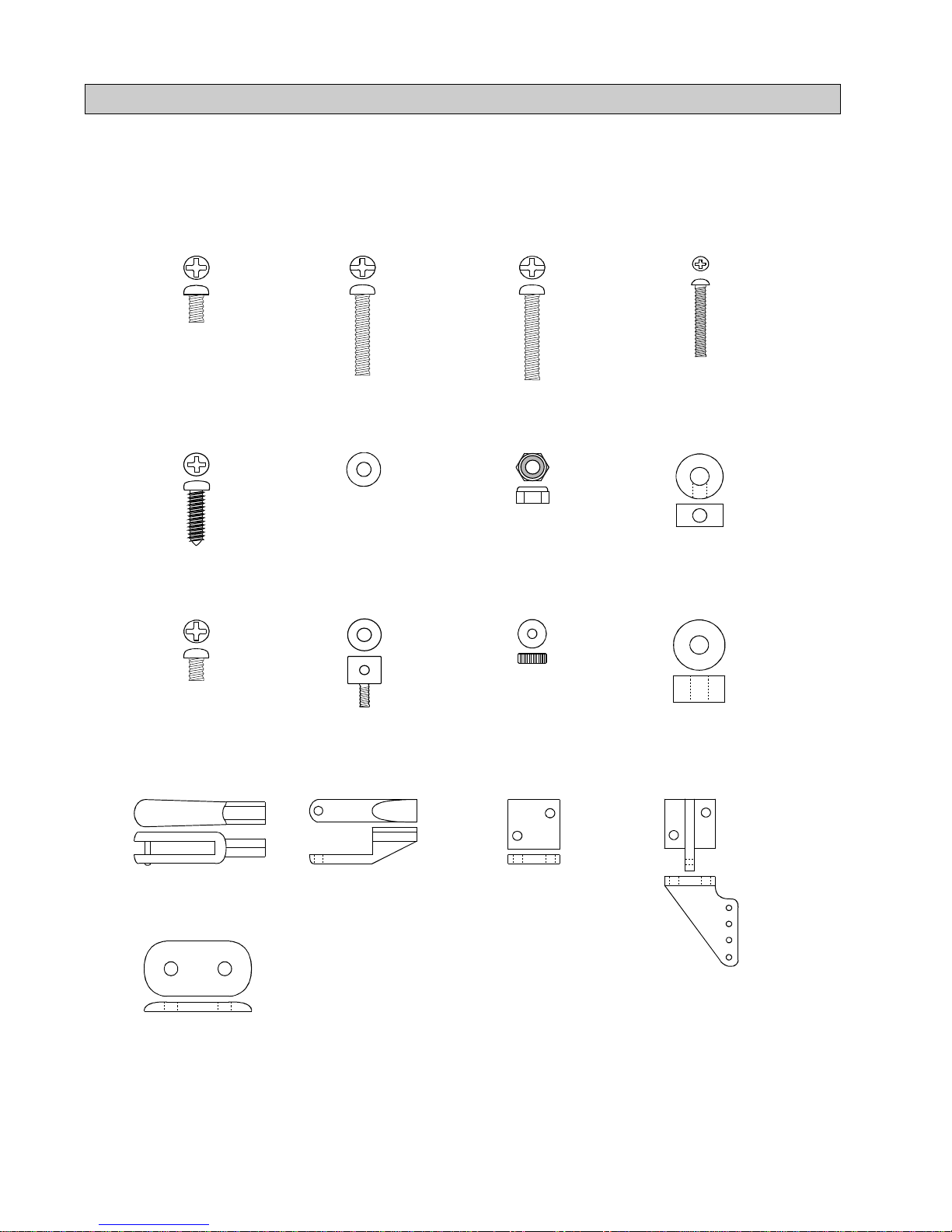
Full Size Hardware Drawings..................................6
Additional Items Required......................................7
Tools and Supplies Needed.....................................7
Field Support Equipment Needed...........................7
Wing Assembly.......................................................8
Installing the Dihedral Brace............................8
Joining the Wing Halves...................................8
Installing the Wing Doubler.............................9
Wing Mounting.......................................................9
Installing the Hold Down Dowels.....................9
Aligning the Wing............................................10
Mounting the Wing..........................................10
Horizontal Stabilizer Installation............................10
Aligning the Horizontal Stabilizer...................10
Mounting the Horizontal Stabilizer..................11
Installing the Triangle Stock............................11
Vertical Stabilizer Installation................................12
Aligning the Vertical Stabilizer.......................12
Mounting the Vertical Stabilizer.....................12
Control Surface Installation...................................12
Hinging the Ailerons........................................12
Hinging the Elevator.......................................13
Hinging the Rudder.........................................13
Main Gear Installation...........................................13
Installing the Main Gear Wires.......................13
Installing the Main Gear Wheels.....................14
Nose Gear Installation...........................................14
Installing the Nose Gear Bracket.....................14
Installing the Nose Gear Wire.........................15
Installing the Nose Gear Wheel.......................15
Engine Mounting....................................................16
Aligning the Engine.........................................16

3
This instruction manual is designed to guide you through the entire assembly process of your new Right
Flyer 40T Mk.II in the least amount of time possible. Along the way you'll learn how to properly as-
semble your new airplane and also learn many tips that will help you in the future. We have listed some
of our recommendations below. Please read through them before going any further.
üPlease read through each step before starting assembly. You should find the layout very complete and
simple. Our goal is to guide you, the beginner, through assembly without any of the headaches and hassles
you might expect.
üWhen you are ready to glue any parts together, test fit them first without using glue. This will ensure you
have the correct parts and that they fit together properly.
üThere are check boxes next to each step. After you complete a step, check off the box. This will help
you keep from losing your place.
üIf you come across this symbol , it means that this is an important point or an assembly hint.
üCover your work table with brown paper or a soft cloth, both to protect the table and to protect the
individual parts.
üKeep a couple of small bowls or jars handy to put the small parts in after you open the accessory bags.
üWe're all excited to get a new airplane in the air, but take your time. This will ensure you build a straight,
strong and great flying airplane.
If you should find a part missing or damaged, or have any questions about
assembly, please contact us at the address below:
Global Hobby Distributors Customer Care
18480 Bandilier Circle
Fountain Valley, CA 92728
Phone: (714) 963-0329
Fax: (714) 964-6236
E-mail: service@globalhobby.com
INTRODUCTION
Thank you for choosing the Global Right Flyer 40T Mk.II ARF. Whether you have built and flown
other R/C airplanes, or if this is your first, you will appreciate the high quality, ease of assembly and
excellent flight characteristics of the Right Flyer 40T Mk.II.
The Right Flyer 40T Mk.II was designed by expert modelers to be one of the best trainer airplanes
availabletoday. Itfeaturesaconstantcordwingwithaflatbottomairfoilforsuperiorslowflighthandling
and forgiving flight characteristics. The long tail moment and large tail surfaces help the airplane fly
very smooth throughout the entire speed range. Tricycle landing gear makes takeoffs and landings a
breeze too. This combination makes the Right Flyer 40T Mk.II one of the best trainers you can buy.
When you open up the box, you'll notice that you won't have much left to do or to purchase to finish
your new airplane. Unlike other trainer kits, the Right Flyer 40T Mk.II comes complete with wheels,
fuel tank, pushrods, clevises and hinges, among many other items. The airframe is completely built
and covered by master craftsmen, who take their time to ensure that every part is straight and properly
glued.
We hope you enjoy your new Global Right Flyer 40T Mk.II as much as we have enjoyed designing
and building it for you. If you have any questions or comments, please feel free to contact us. We
have also included a product survey in the back of this manual. Please take the time to fill it out and
send it to us. We would enjoy hearing any comments or suggestions you may have.

4
KIT CONTENTS
We have organized the parts as they come out of the box for easier identification during assembly. Each photo
below represents the parts that are required in a main section of the assembly process. Before you begin assem-
bly, group the parts like we show. This will ensure you have all of the parts before you begin assembly. It will
also help you become familiar with each part. The corresponding part number is listed first, then the quantity of
that particular part, along with a short description of the part. As you proceed through assembly, you will notice
the same part number listed next to a particular part necessary for that step. If you have any questions as to what
that part might be, refer back to this section.
AIRFRAME ASSEMBLIES
q{1} Fuselage w/Pushrod Housings
q{1} Left Wing Half w/Aileron & Hinges
q{1} Right Wing Half w/Aileron & Hinges
q{1} Horizontal Stabilizer w/Elevator & Hinges
q{1} Vertical Stabilizer w/Rudder & Hinges
1
2
3
4
5
FUEL TANK ASSEMBLY Main Gear ASSEMBLY
q{2} Prebent Main Gear Wires
q{2} 60mm Diameter Wheels
q{2} Nylon Spacers
q{2} Wheel Collars
q{2} 3mm x 6mm Machine Screws
q{4} Nylon Landing Gear Straps
q{8} 3mm x 12mm Wood Screws
19
20
21
22
23
WING ASSEMBLY
q{1} Plywood Dihedral Brace W-3
q{2} Wing Hold Down Dowels W-8
q{1} Precovered Plywood Wing Doubler
q{1} Plywood Aileron Servo Tray
q{2} Hardwood Aileron Servo Tray Blocks
14
15
16
17
18
24
25
1
2
3
5
4
q{1} 240cc Fuel Tank
q{3} Aluminum Tubes
q{1} Weighted Fuel Pickup
q{1} Silicon Fuel Tubing
q{1} 17mm Diameter Rear Plate
q{1} 20mm Diameter Front Plate
q{1} Rubber Stopper
q{1} 3mm x 18mm Machine Screw
6
7
8
9
10
11
12
13
6
12
10
8
11
13
9
7
17
16
14
18
15
20
19
25
24
21 22
23

5
NOSE GEAR ASSEMBLY
q{1} Prebent Nose Gear Wire
q{1} 60mm Diameter Wheel
q{1} Nylon Nose Gear Bracket
q{1} Nylon Nose Gear Steering Arm
q{1} Nylon Spacer
q{2} Wheel Collars
q{3} 3mm x 6mm Machine Screws
q{4} 3mm x 18mm Machine Screws
q{8} 3mm Flat Washers
q{4} 3mm Nylon Insert Nuts
26
27
28
29
30
PUSHROD CONNECTOR ASSEMBLIES
q{2} Nylon Control Horns w/Backplates
q{4} 2mm x 16mm Machine Screws
q{4} Nylon Clevises
q{4} Nylon Snap Keepers
q{2} Adjustable Servo Connectors
44
45
46
47
48
PUSHROD ASSEMBLIES
q{2} 2mm x 95mm Threaded Wires w/L-Bends
q{2} 2mm x 415mm Threaded Wires w/Z-Bends
q{1} 2mm x 530mm Threaded Wire w/L-Bend
q{1} 2mm x 590mm Threaded Wire w/L-Bend
40
41
42
43
MISCELLANEOUS ITEMS
q{4} 3mm x 19mm Machine Screws
q{8} 3mm Flat Washers
q{4} 3mm Nylon Insert Nuts
q{2} Precovered Triangle Stock
36
37
38
39
METRIC CONVERSION CHART
To convert inches into millimeters: Inches x 25.4 = MM
1/64” = .4mm
1/32” = .8mm
1/16” = 1.6mm
3/32” = 2.4mm
1/8” = 3.2mm
5/32” = 4.0mm
3/16” = 4.8mm
1/4” = 6.4mm
3/8” = 9.5mm
1/2” = 12.7mm
5/8” = 15.9mm
3/4” = 19.0mm
1” = 25.4mm
2” = 50.8mm
3” = 76.2mm
6” = 152.4mm
12” = 304.8mm
18” = 457.2mm
21” = 533.4mm
24” = 609.6mm
30” = 762.0mm
36” = 914.4mm
31
32
33
34
35
26
27
29
28
33
34
35 31
30
32
39
36
37
38
42
43
41
40
47
45
44
48 46

6
FULL SIZE HARDWARE DRAWINGS
Listed below are full size drawings of the small hardware items included with the Right Flyer 40T Mk.II. Use
these drawings to familiarize yourself with each part. Please refer back to this page to locate the proper hardware
items when they are needed for a particular assembly step. These drawings are especially helpful when trying to
identify the different size screws or nuts used in a particular step.
IMPORTANT We have included a glossary of terms beginning on page # 31. Use this glossary if you
come across a term that is unfamiliar.
3mm x 6mm
Machine Screw 3mm x 18mm
Machine Screw 3mm x 19mm
Machine Screw 2mm x 16mm
Machine Screw
3mm x 12mm
Wood Screw 3mm Flat
Washer 3mm Nylon
Insert Nut Wheel Collar
3mm x 5mm
Machine Screw
(for servo connector)
Control Horn
Backplate
Control Horn
Nylon Clevis Nylon Snap
Keeper
Servo Connector
Body Servo Connector
Body Nut Nylon Spacer
Nylon Landing
Gear Strap

7
q{1}Hitec 4 or More Channel Radio w/4 Servos
q{1}Cirrus 12” Servo Extension # 444713
q{1}Dubro Foam Rubber # 513
q{1}Global Fuel Line # 115923
q{1}Arco # 64 Rubber Bands # 24649
q{1}Dubro Lead Balance Weight # 351
q{1}Dubro Hook & Loop Material # 348
q{1}Magnum XL .40ARNV # 210740
q{1}APC 10 x 6 Propeller # LP10060
q{1}Thunderbolt Glow Plug # 115493
q{1}Magnum Polished Spinner Nut # 237210
qKwik Bond Thin C/A # 887500
qKwik Bond Thick C/A # 887510
qKwik Bond 30 Minute Epoxy # 887565
qElectric or Hand Drill
qAssorted Drill Bits
qModeling Knife
qMachine Oil or Vaseline
qPhillips Head Screwdriver
q220 Grit Sandpaper w/Sanding Block
qPen or Pencil
qBuilders Triangle
qMasking Tape
qPaper Towels
qRubbing Alcohol
qWire Cutters
qEpoxy Mixing Sticks
qEpoxy Mixing Cups
qStraight Edge Ruler
qMagnum 12V Electric Starter # 361006
qMagnum 12V Fuel Pump # 237377
qMagnum Locking Glow Clip # 237440
qGlobal 12V Battery # 110171
qGlobal 12V Charger # 110270
qMagnum Power Panel # 237390
qGlobal Field Buddy Flight Box # 233072
qMagnum 4-Way Wrench # 237420
FOR 2 CYCLE ENGINE
ADDITIONAL ITEMS REQUIRED
TOOLS AND SUPPLIES NEEDED
FIELD SUPPORT EQUIPMENT NEEDED
OPTIONAL ITEMS
q{1} Cirrus On-Board Battery Indicator # 444762
q{1}Magnum 2-1/4” Chrome Spinner # 237153
q{1}Prather Prop Balancer # 3000
Note - Thepart numbers for the servo extension
and the On-Board Battery Indicator are for Hitec
and JR radio systems. These items are also
available with different connectors for use with
Futaba and Airtronics radio systems.
Global guarantees this kit to be free from defects in both material and workmanship, at the date of purchase. This does
not cover any components parts damaged by use, misuse or modification. In no case shall Global's liability exceed
the original cost of the purchased kit.
In that Global has no control over the final assembly or material used for final assembly, no liability shall be assumed
for any damage resulting from the use by the user of the final user-assembled product. By the act of using the final
user-assembled product, the user accepts all resulting liability.
To make your modeling experience totally enjoyable, we recommend that you get experienced, knowledgable
help with assembly and during your first flights. Your local hobby shop has information about flying clubs in
your area whose membership includes qualified instructors. We also recommend that you contact the AMA at
the address below. They will be able to help you locate a flying field in your area also.
Academy of Model Aeronautics
5151 East Memorial Drive
Muncie, IN. 47302-9252
(800) 435-9262
www.modelaircraft.org

8
PARTS REQUIRED
WING ASSEMBLY
INSTALLING THE DIHEDRAL BRACE
q1) Look at the surface of each root rib on both
wing halves. Notice how the excess covering mate-
rial overlaps onto them. Using a modeling knife,
carefully trim the covering from both of the root ribs,
leavingabout 1/16” of covering overlappingsoit does
not pull away. See photo # 1 below.
q{1} Left Wing Half w/Aileron & Hinges
q{1} Right Wing Half w/Aileron & Hinges
q{1} Plywood Dihedral Brace W-3
q{1} Precovered Plywood Wing Doubler
2
3
14
16
Photo # 1
Removing most of the covering from the two
root ribs will expose more of the wood. This
will result in a stronger joint when the wing halves
are glued together later.
q2) Using a ruler and a pen, locate and mark the
centerline of the plywood dihedral brace W-3. Draw
one vertical line, on each side, at this location. See
photo # 2 below.
Photo # 2
The dihedral brace is cut in the shape of a "V".
The "V" shape should face the top surface of
the wing when the brace is installed. The top surface
of the wing is the curved surface.
q4) Test fit both of the wing halves together with
the dihedral brace temporarily installed. Donotglue
thetwohalves together yet! Thewinghalves should
fit together tight with little or no gaps in the center
section joint. If the center section joint is not tight,
remove the wing halves and lightly sand the edges
and tips of the dihedral brace. Test fit the wing halves
together with the dihedral brace installed again. Re-
peat this step until you are satisfied with the fit of the
wing halves and the dihedral brace.
It is important that the wing halves fit together
properly. The better the fit, the stronger the cen-
ter section joint will be.
q5) Whensatisfied with the fit of thewinghalves,
remove the wing halves and the dihedral brace.
q6) Mix a generous amount of Kwik Bond 30
Minute Epoxy. Working with only one wing half for
now, apply a thin layer of epoxy inside the plywood
dihedralbraceboxandto onlyhalfof thedihedralbrace.
Make sure to cover the top and bottom, as well as the
sides, and use enough epoxy to fill any gaps.
Mixequal amounts of epoxyfor about 1 minute.
This will ensure both parts are thoroughly in-
corporated together.
q7) Slide the dihedral brace into the plywood box
up to the centerline. Remove any excess epoxy be-
fore it dries using a paper towel and rubbing alcohol.
Allow the epoxy to cure before proceeding.
Photo # 3
JOINING THE WING HALVES
q8) Once the epoxy has cured, trial fit both wing
halves together to double check that the wing halves
still fit correctly.
q3) Test fit the plywood dihedral brace into the
plywood dihedral brace box in each wing half. The
brace should slide into each wing half up to the cen-
terline. If it does not, remove the brace and lightly
sand the edges and tips until the proper fit is obtained.
See photo # 3 at top right.

9
Photo # 4
q11) Once the epoxy has fully cured, double
check the center section joint. If any gaps are present,
mix a small amount of Kwik Bond 30 Minute Epoxy
and carefully fill any remaining gaps. Remove any
excess epoxy and allow it to cure thoroughly before
proceeding.
INSTALLING THE WING DOUBLER
q12) Set the plywood wing doubler in place on
top of the wing. The back edge of the doubler should
be even with the trailing edge of the wing and the
sides of the doubler should overlap the centerline of
the wing equal amounts. See photo # 5 below.
Photo # 5
q13) While holding the doubler in place, use a
pen and draw around the doubler to outline it onto
the top of the wing.
PARTS REQUIRED
WING MOUNTING
INSTALLING THE HOLD DOWN DOWELS
q{1} Fuselage w/Pushrod Housings
q{2} Wing Hold Down Dowels W-8
1
15
q1) Using a modeling knife, remove the cover-
ing from over the two predrilled wing hold down
dowel holes in front of the wing saddle. One hole is
located on each side of the fuselage 9” behind the
front of the fuselage and 1/2” down from the top of
the fuselage.
q2) Remove the covering from over the two pre-
drilled wing hold down dowel holes in back of the
wing saddle. One hole is located on each side of the
fuselage 20-3/8” behind the front of the fuselage and
1/2” down from the top of the fuselage.
q3) Slide one wing hold down dowel through the
two front holes and one through the two back holes.
Center the two dowels in the fuselage. Both ends of
each dowel should protrude from the fuselage sides
equal amounts. See photo # 6 below.
q9) Mix a generous amount of Kwik Bond 30
Minute Epoxy. Apply a thin layer of epoxy to the
exposed half of the dihedral brace, the inside of the
plywood box in the second wing half, and the entire
surface of both root ribs. Make sure to use enough
epoxy to fill any gaps.
q10) Slide the two wing halves together and care-
fully align them at the leading and trailing edges.
Wipe away any excess epoxy using a paper towel and
rubbing alcohol. Use masking tape to hold the two
wing halves in place until the epoxy fully cures. See
photo # 4 below.
q14) Remove the doubler. Using a modeling
knife, carefully remove the covering from just inside
the outline.
When cutting through the covering, cut with
enough pressure to only cut through the cover-
ing itself. Try not to cut down into the wood.
Removing the covering will allow a better bond be-
tween the two parts. Glue does not stick well to the
covering material used on R/C models, so always re-
member to remove the covering from any surface to
be glued.
q15) Glue the doubler to the wing using Kwik
Bond Thick C/A. Hold the doubler firmly in place
until the glue fully cures.
Photo # 6

10
q4) When satisfied with their fit, use a pencil and
place a mark on each dowel were they exit the fuse-
lage sides. Remove the two dowels.
q5) Mixa small amount of KwikBond30 Minute
Epoxy. Using a mixing stick, apply a thin layer of
epoxy to the inside edges of each of the four holes in
the fuselage sides.
q6) Slide the dowels back into place, aligning the
marks on the dowels with the fuselage sides. Use a
paper towel and rubbing alcohol remove any excess
epoxy. Allow the epoxy to cure before proceeding.
ALIGNING THE WING
q7) Using a ruler and a pen, locate the centerline
of the fuselage at both the front and the rear of the
wing saddle. Place one mark on top of the fuselage at
the back edge of the wing saddle and one mark at the
front of the wing saddle. See photo # 7 below.
Photo # 7
These two marks will help you align the wing
when you install it onto the fuselage. You may
wish to make these marks in permanent ink so you
can align the wing correctly each time you install the
wing. This will ensure the wing is aligned properly
every time you fly the airplane.
q8) Place the wing onto the wing saddle. The
joint where the two wing halves were glued together
is considered the centerline of the wing. Align the
centerline of the wing at both the front and the rear of
the wing saddle with the two centerline marks you
made on the fuselage.
q9) Using a couple of # 64 rubber bands, tempo-
rarily install the wing. To properly install the rubber
bands, hook one over one of the front wing hold down
dowels, carefully pull it back over the wing and hook
it over the rear hold down dowel on the same side.
Install two rubber bands on each side for now.
MOUNTING THE WING
HORIZONTAL STABILIZER
INSTALLATION
PARTS REQUIRED
ALIGNING THE HORIZONTAL STABILIZER
q{1} Horizontal Stabilizer w/Elevator & Hinges
q{2} Precovered Triangle Stock
4
39
Photo # 8
q1) Remove the elevator from the horizontal sta-
bilizer. Using a ruler and a pen, locate the centerline
of the horizontal stabilizer, at the trailing edge, and
place a mark. Use a triangle and extend this mark,
from back to front, across the top of the stabilizer.
Also extend this mark down the back of the trailing
edge. See photo # 8 below.
q2) Using a modeling knife, remove the cover-
ing from over the top of the precut hole in the center
of the stabilizer. The hole is located 2” behind the
leading edge and is 1” long and 3/16” wide.
q3) Using a ruler and a pen, locate and mark the
centerline of the fuselage at both the front and the
rear of the stabilizer mounting platform. When you
place the mark at the rear of the platform, extend the
mark down the back edge of the fuselage. This will
make it easier to line up the horizontal stabilizer. See
photo # 9 below.
Photo # 9
q4) Set the stabilizer onto the stabilizer mount-
ing platform and push it as far forward as possible.
q5) Carefully remove bothaileronsfromthewing.
Align the centerline drawn on the top and the rear of

11
Figure # 1
Figure # 2
A = A-1
B = B-1
q6) When you are satisfied with the alignment,
holdthestabilizersecurelyinplacewithmasking tape,
but do not glue it in place at this time.
MOUNTING THE HORIZONTAL STABILIZER
q7) With the stabilizer held firmly in place, use a
pen and draw lines onto the stabilizer where it and
the fuselage sides meet. Do this on both the right and
left sides on the bottom of the stabilizer.
q8) Remove the stabilizer from the fuselage. Us-
ingthelinesyoujustdrewasaguide,carefullyremove
the covering from between them using a modeling
knife. See photo # 10 below.
Photo # 10
When cutting through the covering to remove
it, cut with only enough pressure to only cut
throughthe covering itself. Cutting intothebalsa may
weaken the stabilizer.
q9) Using a modeling knife, carefully remove the
covering from the top of the stabilizer mounting sides
on the fuselage.
Removing the covering will allow a better bond
between the two parts. If the glue joint between
the fuselage sides and the stabilizer is not adequate, it
could lead to stabilizer failure during flight.
q10) When you are sure that everything is aligned
correctly, mix up a generous amount of Kwik Bond
30 Minute Epoxy. Apply a thin layer to the mounting
area on the bottom of the stabilizer and to the top of
the stabilizer mounting sides on the fuselage. Set the
stabilizer in place and realign. Double check all of
yourmeasurements once more before the epoxycures.
Hold the stabilizer in place with masking tape and
remove any excess epoxy using a paper towel and
rubbing alcohol.
INSTALLING THE TRIANGLE STOCK
q11) Using a modeling knife, remove the cover-
ing that overlaps onto the inside edges of the two
pieces of triangle stock.
q12) Working with one piece of triangle stock for
now, align it in the joint between the bottom of the
stabilizer and the fuselage side. When it's properly
aligned,the triangle stock shouldbecentered between
the leading edge and trailing edge of the stabilizer.
See photo # 11 below.
Photo # 11
the stabilizer with the centerline marks drawn on the
fuselage. When those are aligned, hold the stabilizer
in that position using masking tape. Align the hori-
zontal stabilizer with the wing. When viewed from
the rear, the horizontal stabilizer should be level with
the wing. If it is not level, use 220 grit sandpaper
with a sanding block and sand down the high side of
thestabilizermountingplatformuntiltheproperalign-
ment is achieved. The tips of the stabilizer should
also be equal distance from the tips of the wing. See
figures # 1 and # 2 below.
q13) When satisfied with the alignment, hold the
triangle stock in place and draw around it using a pen.
q14) Remove the triangle stock and use a model-
ing knife to remove the covering from inside the
outline you drew.

12
VERTICAL STABILIZER
INSTALLATION
PARTS REQUIRED
ALIGNING THE VERTICAL STABILIZER
q{1} Vertical Stabilizer w/Rudder & Hinges
5
q1) Remove the rudder from the vertical stabi-
lizer and set it aside for now.
q2) Slide the tab in the back of the vertical sta-
bilizer into the precut hole in the horizontal stabilizer.
The dorsal fin on the front of the vertical stabilizer
should be centered between the fuselage sides and it
should be firmly pushed down so there are no gaps
present.
q3) While holding the vertical stabilizer firmly
in place, use a pen and draw a line on each side of it
whereitmeetsthetopofthehorizontal stabilizer. Also
draw an outline on top of the fuselage and horizontal
stabilizer where they and the dorsal fin meet.
q4) Remove the stabilizer. Using a modeling
knife, remove the covering from below the lines you
drew. Also remove the covering from thebottomedge
of the stabilizer, the bottom edge of the dorsal fin and
between the lines you drew on top of the fuselage
and horizontal stabilizer. See photo # 12 below.
Photo # 12
When cutting through the covering to remove
it, cut with only enough pressure to only cut
through the covering itself. Cutting into the balsa
may weaken the stabilizer.
q5) Set the vertical stabilizer back in place. Us-
ing a triangle, check to ensure that the vertical
stabilizer is aligned 90º to the horizontal stabilizer.
See figure # 3 below.
Figure # 3
MOUNTING THE VERTICAL STABILIZER
q6) When you are sure that everything is aligned
correctly, mix up a generous amount of Kwik Bond
30 Minute Epoxy. Apply a thin layer to the mount-
ing slot in the horizontal stabilizer and to the sides
and bottom of the vertical stabilizer mounting area.
Apply epoxy to the bottom edge of the dorsal fin and
to the top of the fuselage also. Set the stabilizer in
place and realign. Double check all of your measure-
ments once more before the epoxy cures. Hold the
stabilizer in place with masking tape and remove any
excess epoxy using a paper towel and rubbing alco-
hol. Allow the epoxy to fully cure before proceeding.
CONTROL SURFACE
INSTALLATION
HINGING THE AILERONS
q1) The C/A hinges have already been glued into
the two ailerons. Working with one aileron at a time,
slide the aileron and it's hinges into their precut hinge
slots in the trailing edge of the wing, making sure the
torque rod is firmly seated into the predrilled hole in
the leading edge of the aileron. Slide the aileron in
until it is tight against the trailing edge of the wing.
Themaximum hingegapshouldbe nomorethan1/32”.
q2) When satisfied with the fit, remove the aile-
ron. Using a modeling knife, carefully remove any
excess covering material that may have overlapped
onto the hinges. Be careful not to cut through the
hinges!
q15) Glue the triangle stock into place using a
generous amount of Kwik Bond Thick C/A. Allow
the glue to cure completely before proceeding.
The triangle stock adds a lot of strength to the
joint between the fuselage and stabilizer. It's
important that it be glued in securely.
q16) Repeat steps # 12 - # 15 to install the second
pieceof triangle stock onthe opposite side ofthe hori-
zontal stabilizer.

13
q3) Slide a small piece of waxed paper between
theailerontorquerodandthetrailingedge of the wing.
See photo # 13 below.
The waxed paper will prevent epoxy from glu-
ingthetorquerodtothe trailing edge of the wing.
q4) Mix up a small amount of Kwik Bond 30
Minute Epoxy. Apply a thin layer of epoxy to the
aileron torque rod. Use a toothpick and pack epoxy
into the predrilled hole in the aileron.
q5) Slide the aileron and it's hinges into their pre-
cuthinge slots in the trailingedgeof the wing, making
sure the torque rod is firmly seated in the predrilled
hole in the aileron.
q6) With the aileron tight against the wing, ro-
tate the aileron down about 45º. Apply six drops of
KwikBond ThinC/Atothe exposedareaofeach hinge.
Turn the wing over and repeat for the other side of the
hinges. Allow the glue to cure for about ten minutes.
Once cured, the aileron may be stiff and difficult to
move. Thisisnormal. Gentlymovetheaileronupand
down about five to ten times to free it up.
q7) Repeat steps # 1 - # 6 to install the second
aileron.
Photo # 13
HINGING THE ELEVATOR
q8) Using a modeling knife, carefully remove any
excess covering material that may have overlapped
onto the hinges. Be careful not to cut through the
hinges!
q9) The C/A hinges have already been glued into
the elevator. Slide the elevator and it's hinges into
their precut hinge slots in the trailing edge of the sta-
bilizer. The elevator should fit tight against the trailing
edge and the hinge gap should be no more than 1/32”.
The tips of the elevator should be even with the tips
of the stabilizer.
q10) When you are satisfied with the fit, hold the
elevator tight against the stabilizer and rotate the el-
evatordownabout45º. ApplysixdropsofKwikBond
Thin C/A to the exposed area of each hinge. Turn the
fuselage over and repeat for the other side of the
hinges. Allow the glue to cure for about ten minutes.
Once cured, the elevator may be stiff and difficult to
move. This is normal. Gently move the elevator up
and down about five to ten times to free it up.
q11) Using a modeling knife, carefully remove
any excess covering material that may have over-
lappedontothehinges. Becarefulnot tocut through
the hinges!
q12) The C/A hingeshavealreadybeengluedinto
the rudder. Slide the rudder and it's hinges into their
precut hinge slots in the trailing edge of the vertical
stabilizer. The rudder should fit tight against the trail-
ing edge and the hinge gap should be no more than
1/32”. The tip of the rudder should be even with the
tip of the stabilizer.
q13) When you are satisfied with the fit, hold the
rudder tight against the stabilizer and rotate the rud-
der to the side about 45º. Apply six drops of Kwik
Bond Thin C/A to the exposed area of each hinge.
Turn the fuselage over and repeat for the other side of
the hinges. Allow the glue to cure for about ten min-
utes. Once cured, the rudder may be stiff and difficult
to move. This is normal. Gently move the rudder
back and forth about five to ten times to free it up.
HINGING THE RUDDER
PARTS REQUIRED
MAIN GEAR INSTALLATION
INSTALLING THE MAIN GEAR WIRES
q{2} Prebent Main Gear Wires
q{2} 60mm Diameter Wheels
q{2} Nylon Spacers
q{2} Wheel Collars
q{2} 3mm x 6mm Machine Screws
q{4} Nylon Landing Gear Straps
q{8} 3mm x 12mm Wood Screws
19
20
21
22
23
24
25
q1) Using a modeling knife, remove the cover-
ing from over the main gear mounting slot located in
the bottom of the fuselage. The slot is located 9”
back from the front edge of the firewall. It is 5/16”
wide and 3-1/2” long.

14
q2) Insert the 90º bend of each main gear wire
into the predrilled holes in the mounting slot. See
photo # 14 below.
q3) The gear wires are held in place using four
nylon landing gear straps and eight 3mm x 12mm
wood screws. Each strap should be centered over the
gear wires and should also be spaced equally between
the fuselage sides.
q4) Usingthe landing gear straps as aguide,mark
the locations of the eight 3mm x 12mm mounting
screws onto the fuselage using a pen.
q5) Remove the straps. Using a 1/16” drill bit,
drill eight 1/16” holes into the fuselage to accept the
wood screws.
q6) Install the four nylon landing gear straps us-
ing eight 3mm x 12mm wood screws. Tighten the
screws completely to secure the landing gear wires
in place. See photo # 15 below.
Photo # 14
Photo # 15
INSTALLING THE MAIN GEAR WHEELS
q7) Slide one nylon spacer, then one wheel and
one wheel collar with set screw onto one axle.
The wheel should be installed with the recessed
portion of the rim towards the nylon spacer.
q8) Center the wheel on the axle and tighten the
set screw in the wheel collar. Check to make sure the
wheel spins free. See photo # 16 at top right.
Photo # 16
q9) Repeat steps # 7 and # 8 to install the second
wheel on the opposite axle.
PARTS REQUIRED
NOSE GEAR INSTALLATION
INSTALLING THE NOSE GEAR BRACKET
q{1} Prebent Nose Gear Wire
q{1} 60mm Diameter Wheel
q{1} Nylon Nose Gear Bracket
q{1} Nylon Nose Gear Steering Arm
q{1} Nylon Spacer
q{2} Wheel Collars
q{3} 3mm x 6mm Machine Screws
q{4} 3mm x 18mm Machine Screws
q{8} 3mm Flat Washers
q{4} 3mm Nylon Insert Nuts
q{1} 2mm x 415mm Threaded Wire w/Z-Bend
26
27
28
29
30
31
32
33
34
35
q1) Install the nylon nose gear bracket to the
bottom of the firewall using the four 3mm x 18mm
machine screws, eight 3mm flat washers and four
3mm nylon insert nuts. The holes for the machine
screws have already been predrilled in the proper
positions. Tighten the screws and nuts completely to
secure the bracket in place. See photo # 17 below.
Photo # 17
The nylon nose gear mounting bracket has a
molded lip on one end of it. When installing
the bracket, make sure the molded lip points towards
the bottom of the fuselage.
41

15
INSTALLING THE NOSE GEAR WIRE
q2) Thread one 3mm x 6mm machine screw into
the side of the nylon steering arm. Slide the nylon
steering arm onto the nose gear wire. Orientate the
arm so that the set screw is aligned with the flat spot
on the wire. When satisfied with the alignment,
tighten the set screw securely. Seephoto #18 below.
Photo # 18
Photo # 19
q4) Slide the nose gear wire into the mounting
bracket. Push the nose gear down until it stops.
When installing the nose gear wire, make sure
the coil in the wire points toward the back of
the fuselage.
q5) Slidetheplain end ofthe2mmx415mm push-
rod wire into the slot in the bottom of the fuselage.
Look inside the fuselage and feed the wire through the
predrilled hole in the forward bulkhead and through
the hole in the servo tray support bulkhead.
q6) Using a pair of pliers, carefully bend the push-
rod wire at an angle until the Z-bend lines up with the
hole in the nose gear steering arm.
When installing the steering arm, make sure the
mounting flange faces the top of the nose gear.
q3) Using a modeling knife, cut a slot in the bot-
tom, left side of the fuselage for the steering pushrod
wire to exit. The slot should be 1-1/4” long and 1/4”
wide. Position the slot 1-1/4” behind the firewall and
1/4” in from the fuselage side. See photo # 19 below.
q7) Remove the nose gear. With the pushrodwire
still in place, connect the Z-bend in the pushrod wire
to the predrilled hole in the steering arm. Slide the
nose gear wire back into the mounting bracket. Twist
thenosegear back and forth. If any binding ispresent,
make a small bend in the pushrod wire where it exits
the slot in the fuselage. See photo # 20 below.
Photo # 20
q8) Push the nose gear wire down until it stops.
The steering arm should be pressed firmly against the
mounting bracket.
q9) Thread one 3mm x 6mm machine screw into
the side of one wheel collar. With the nose gear wire
in place, slide the wheel collar over the top of the
gear wire and tighten the machine screw to secure the
nose gear wire in place. See photo # 21 below.
Photo # 21
INSTALLING THE NOSE GEAR WHEEL
q10) Slide one nylon spacer, then one wheel and
one wheel collar with set screw onto the axle.
The wheel should be installed with the recessed
portion of the rim toward the nylon spacer.
q11) Center the wheel on the axle and tighten the
set screw in the wheel collar. Check to make sure the
wheel spins free.

16
PARTS REQUIRED
ENGINE MOUNTING
ALIGNING THE ENGINE
q{4} 3mm x 19mm Machine Screws
q{8} 3mm Flat Washers
q{4} 3mm Nylon Insert Nuts
36
37
38
q1) Install a 10 x 6 propeller onto your Magnum
XL .40ARNV engine. Tighten the prop nut to secure
the propeller in place.
q2) Set the engine onto the hardwood motor
mount rails and rotate the propeller so it is horizontal.
To properly align the engine, use a ruler and measure
from the front of each fuselage side, to the back edge
of the propeller. The measurement on the left should
be1/2”. Themeasurement on the right should be 3/8”.
See photo # 22 below.
Photo # 22
If you're using an engine that has a crankcase
dimensionwider than the width of thehardwood
mounting rails, you can remove equal amounts of
woodfrom the inside edge of eachrail. Removesmall
amounts at a time until your engine fits properly, but
be careful not to remove too much material. A cop-
ing saw, is best to use to do this with, but a sharp
modeling knife will work well also.
q3) When satisfied with the alignment, hold the
engine firmly in place and use a pencil to mark the
locations of the four mounting holes onto the hard-
wood motor mount rails.
q4) Remove the engine. Using a 1/8” drill bit,
drillthefourmountingholesthroughthemotormount.
When drilling the holes, make sure you drill
them straight down and not at an angle.
q5) Setthe engine back in place anddoublecheck
thatthe holes in theenginemounting lugs line upwith
the holes in the engine mount. Install the engine us-
ing four 3mm x 19mm machine screws, eight 3mm
flat washers and four 3mm nylon insert nuts. Tighten
the screws and nuts completely to secure the engine
in place.
q6) If your engine is equipped with a rear needle
valve assembly, install that and the carburetor onto
your engine now. You will have to cut a slot in the
side of the fuselage to clear the needle valve. Use a
modeling knife to do this. See photo # 23 below.
Photo # 23
PARTS REQUIRED
FUEL TANK
STOPPER ASSEMBLY
q{1} 240cc Fuel Tank
q{3} Aluminum Tubes
q{1} Weighted Fuel Pickup
q{1} Silicon Fuel Tubing
q{1} 17mm Diameter Rear Plate
q{1} 20mm Diameter Front Plate
q{1} Rubber Stopper
q{1} 3mm x 18mm Machine Screw
6
7
8
9
10
11
12
13
q1) The fuel tank assembly incudes 3 different
length aluminum tubes. Discard the shortest of the
three tubes. It will not be used.
The 50mm long tube is used for the fuel line
pickup and the 80mm long tube is used for the
vent/pressure line. The fuel line pickup goes to the
fuel nipple on the carburetor, or rear needle valve,
and the vent/pressure line goes to the pressure tap on
the muffler.
q2) Using 220 grit sandpaper carefully smooth
each end of the two tubes. This will prevent the fuel
line from being accidentally cut when it is installed.
q3) Push the two aluminum tubes through the rub-
ber stopper until 1/2” of each tube protrudes from the

17
front of the stopper. Slide the 20mm diameter front
plate over the tubes at the front of the stopper and
slide the 17mm diameter rear plate over the tubes at
the rear of the stopper. Insert the 3mm x 18mm ma-
chine screw into the center hole in the front plate,
then screw it through the stopper and into the back
plate. Do not tighten the screw yet.
q4) Carefully bend the longer of the two tubes
up at a 45º angle. This tube is the vent tube. When
the stopper assembly is installed in the tank, the top
of the vent tube should rest just below the top of the
tank. Make a gradual bend, so you don't pinch the
tube when you bend it.
q5) Slide the silicon fuel tubing, with the
weighted pickup attached to one end, onto the fuel
pickup tube, until the silicon tube touches the rear
plate. See photo # 24 below.
Photo # 24
q6) Test fit the stopper assembly into the molded
hole in the front of the tank. If there is any plastic
flashing around the tank opening, remove it using a
modeling knife. Make sure none falls into the tank.
q7) With the stopper assembly in place, the
weighted pickup should move freely inside the tank
and the top of the vent tube should rest just below
the top of the tank, but not rub against the tank. See
photo # 25 below.
INSTALLING THE STOPPER
If the tubes do not fit right, remove the stopper
assembly and adjust them before proceeding.
q8) When satisfied with the alignment of the stop-
perassemblytightenthe 3mm x 18mm machine screw
until the rubber stopper expands and seals the tank
opening. Do not overtighten the assembly as this
could cause the tank to split.
Photo # 25
FUEL TANK INSTALLATION
q9) Using a modeling knife, cut two piecesofsili-
confueltubingto12”long. Slidebothpiecesoftubing
through the precut hole in the top of the firewall and
into the servo compartment.
q10) Install the two lengths of silicon fuel tubing
onto the vent and fuel pickup tubes at the front of the
tank. Use a pen to mark the other ends of the tubes
with a P for pressure and a C for carburetor so you
remember which one goes where.
q11) Cut a piece of Dubro foam rubber and wrap
it around your receiver battery pack. Use a couple of
longpiecesofmaskingtape,wrappedaroundthepack,
to hold the foam in place. See photo # 26 below.
Photo # 26
q12) Place the battery pack on the fuselage floor,
inside the fuel tank compartment. Push it up against
the firewall and make sure it is as far away from the
steering pushrod as possible.
If you are using a square battery pack it will not
fit inside the fuel tank compartment. Therefore,
you will need to mount it behind the fuel tank. Be-
cause of this you may have to add weight to properly
balancethe airplane. Don't worry about that untillater
though.
q13) Pull on the two fuel lines while guiding the
fuel tank in position.

18
q15) Cut pieces of Dubro foam rubber and wedge
them between the tank and the fuselage, being care-
ful not to interfere with the steering pushrod or the
area where the throttle pushrod will be installed.
When your done, the fuel tank should fit firmly in
place and not move around.
Do not push the fuel tank any farther forward.
Doing this will pinch the fuel lines between the
tankand the firewall, causingfuelflow problems later
on. To double check the lines, carefully blow through
one of them. You should hear and feel air coming out
of the other tube.
When installing the fuel tank, make sure the top
of the tank is facing the top of the fuselage.
q14) When properly aligned, the front portion of
the fuel tank should rest on top of the battery pack and
the back edge of the tank should be about 3/8” past the
forward bulkhead. See photo # 27 below.
Photo # 27
PARTS REQUIRED
SERVO INSTALLATION
INSTALLING THE FUSELAGE SERVOS
q{1} Plywood Aileron Servo Tray
q{2} Hardwood Aileron Servo Tray Blocks
17
18
q1) Locate the three servos you intend to use for
the elevator, rudder/steering and throttle controls. In-
stall the four rubber grommets and four brass collets
onto each of the servos. The brass collets should be
installed with the flanges facing the bottom of the
servo mounting tabs. See figure # 4 below.
q2) Position the servos into the preinstalled servo
tray making sure you run the servo wires out the pre-
cut hole in the forward servo tray bulkhead. Note the
positionof each oftheservooutputshafts. They should
face the directions shown. See photo # 28 below.
Figure # 4
Photo # 28
To make it easier, position the two rear servos
first, then run those wires out the precut hole.
After that you can position and run the lead out of the
precut hole for the forward servo.
q3) Using a 1/16”drillbit,drillpilotholesthrough
the servo tray for each of the mounting screws. In-
stall the servos using the mounting screws provided
with each servo. Tighten the screws firmly to hold
the servos in place.
Drilling pilot holes through the servo tray will
make it easier to install the mounting screws.
INSTALLING THE AILERON SERVO TRAY
q4) Using a modeling knife, cut a shallow "V"
shape into the bottom of each of the two hardwood
blocks. The blocks are 1” wide and 7/8” tall. Cut the
"V" shape on the tall side. See photo # 29 below.
Photo # 29
Be careful not to remove too much material at
this time. You will double check the fit in the
next step.
q5) Test fit the two hardwood blocks into the
precut aileron servo hole in the bottom of the wing.
Each block should fit firmly between the sides of the

19
Photo # 30
Because this fit will be different on every air-
plane, you may need to lightly sand the sides of
the blocks so they will fit properly.
q6) When satisfied with their fit, remove the two
blocks. Using Kwik Bond Thick C/A, glue the two
hardwood blocks to one side of the plywood aileron
servo tray. One block should be glued flush with the
outer edge of the tray and the second block should be
glued flush with inside edge of the servo cutout. Both
blocks should be centered between the sides of the
tray. See photo # 31 below.
hole and the "V" shape should match the angle of
the top wing sheeting. See photo # 30 below.
Photo # 31
q7) Test fit the aileron servo tray assembly into
the wing. The portion of the tray that overhangs the
hardwood block should face the trailing edge of the
wing and the whole assembly should be pushed down
firmly into the hole. See photo # 32 below.
Photo # 32
q8) When satisfied with the fit, remove the servo
tray assembly. Mix up a generous amount of Kwik
Bond 30 Minute Epoxy. Apply a thin layer of epoxy
to the gluing surfaces of each of the two hardwood
blocks. Reinstall the servo tray assembly and align it
asdonepreviously. Anyexcessepoxycanberemoved
using a paper towel and rubbing alcohol. Allow the
epoxy to fully cure before proceeding.
INSTALLING THE AILERON SERVO
q9) Locate the servo you intend to use for aile-
roncontrol. Install the four rubbergrommetsand four
brass collets onto the servo. The brass collets should
be installed with the flanges facing the bottom of the
servo mounting tabs. See figure # 5 below.
q10) Position the servo into the servo tray mak-
ing sure you run the servo wire out between the tray
and the wing. Note the position of the servo output
shaft. It should face the leading edge of the wing.
See photo # 33 below.
Figure # 5
Photo # 33
q11) Using a 1/16” drill bit, drill pilot holes
throughtheservotrayforeach of the mounting screws.
Install the servo using the mounting screws provided
with the servo. Tighten the screws firmly to hold the
servo in place.
Drilling pilot holes through the servo tray will
make it easier to install the mounting screws.
Be careful not to drill through the top of the wing.

20
PARTS REQUIRED
THROTTLE PUSHROD
INSTALLING THE PUSHROD WIRE
q{1} 2mm x 415mm Threaded Wire w/Z-Bend
q{1} Adjustable Servo Connector
41
48
q1) Slide the plain end of the pushrod wire
through the predrilled hole in the firewall, directly
behind the throttle arm, through the hole in the for-
ward bulkhead and through the hole in the forward
servo tray support bulkhead.
q2) Remove the throttle arm from the engine and
attachtheZ-Bend to the hole farthest out inthethrottle
arm. Reattach the throttle arm to the engine. See
photo # 34 below.
Photo # 34
The hole in your throttle arm may be too small
for the pushrod wire to fit through. If it is, drill
out the hole using a 5/64” drill bit.
INSTALLING THE SERVO CONNECTOR
q3) Locate a plastic servo arm that came with
your servo. Using wire cutters, remove all but one
of the arms.
q4) Install one adjustable servo connector
through the third hole out from the center of the arm.
You will have to enlarge the hole in the servo arm
using a 5/64” drill bit so the servo connector will fit.
When you thread the nut on, don't tighten it com-
pletely. You don't want the connector loose, but you
do want it to be able to rotate without binding too
much. See figure # 6 below.
Figure # 6
After installing the adjustable servo connector
apply a small drop of Kwik Bond Thin C/A to
the nut. This will prevent the connector from loosen-
ing during flight.
q5) Plug the throttle servo lead into your receiver
and turn on the radio system (please refer to your
radio system manual for complete instructions about
connecting your system).
q6) Check to ensure that the throttle servo output
shaft is moving in the correct direction. When the
throttlestickis moved forward from idletofullthrottle,
the servo should rotate counterclockwise.
q7) Slide the adjustable servo connector/servo
arm assembly over the plain end of the pushrod wire.
Position the throttle stick and the throttle trim at their
lowest positions.
q8) Manually push the carburetor barrel fully
closed. Angle the servo arm about 45º back from
center and attach the servo arm to the servo. The
servo arm should be pointing toward the fuselage
side. With the carburetor barrel fully closed, tighten
the set screw in the adjustable servo connector.
q9) Remove the excess throttle pushrod wire us-
ing wire cutters and install the servo arm retaining
screw. See photo # 35 below.
Photo # 35
ADJUSTING THE THROTTLE LINKAGE
q10) When your throttle linkage is adjusted prop-
erly, the carburetor barrel should be fully closed when
the throttle stick and the throttle trim lever are at their
lowest positions. Moving the throttle trim up should
open the carburetor barrel about 25% - 30%. Mov-
ing the throttle stick all the way forward should open
thethrottlebarrel completely. All of these movements
should be done without any binding in the linkage.
Sometimestheservowillbindateitherthefullyclosed
and/or fully open throttle positions. If this happens,
Table of contents
Other Global Toy manuals
Popular Toy manuals by other brands

Radio Shack
Radio Shack Frenzy owner's manual

Nienhuis
Nienhuis Toys for Life 3.703.00 instructions

Hasbro
Hasbro Disney STAR WARS MANDALORIAN GALACTIC ACTION... Disassembly

Dynamite
Dynamite T-MAXX .21CONVERSION instructions

MOB
MOB MO6710 user manual

Fisher-Price
Fisher-Price TWIN TIME DOLLHOUSE H3370 user manual