© Globel Industries Pty Ltd
GI00045 September 30 2015
Choking Hazard - This product contains small parts.
It's Not That Difficult!
IMPORTANT! Read These Instructions FIRST.
The construction of your shed isn't as complicated as it may first appear.
Our step by step, illustrated instructions are easy to follow, and we provide hints
to make the assembly even easier. Simply follow our recommendations and carefully study
our illustrations, then your garden shed will be assembled quickly and accurately.
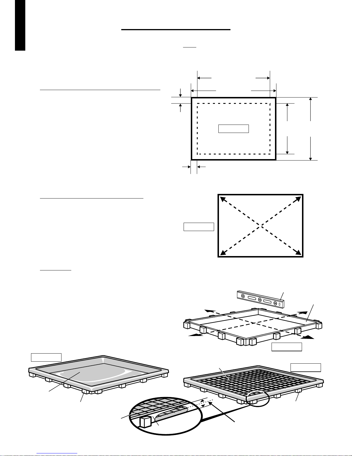
Make sure the site you choose for your garden shed is firm and level, and water drains away from the site.
Do not install the garden shed in areas subject to high winds.
Do not assemble the garden shed on a windy day.
Your garden shed should be assembled on a specifically prepared base, ie concrete slab or pavers (or a suitable
Garden Shed Foundation Kit) and then secured using the recommended dyna bolts as listed in the "Tools Required" page.
A heavy duty polythene sheet should be placed under the foundation to assist in reducing rising dampness from the soil,
thus reducing condensation build up in your garden shed.
Once secured, we highly recommend applying silicone along the inside of the base rail to prevent water from seeping under
the base frame and into your shed.
Do not backfill against the shed's walls or base, as this will cause corrosion and void the warranty.
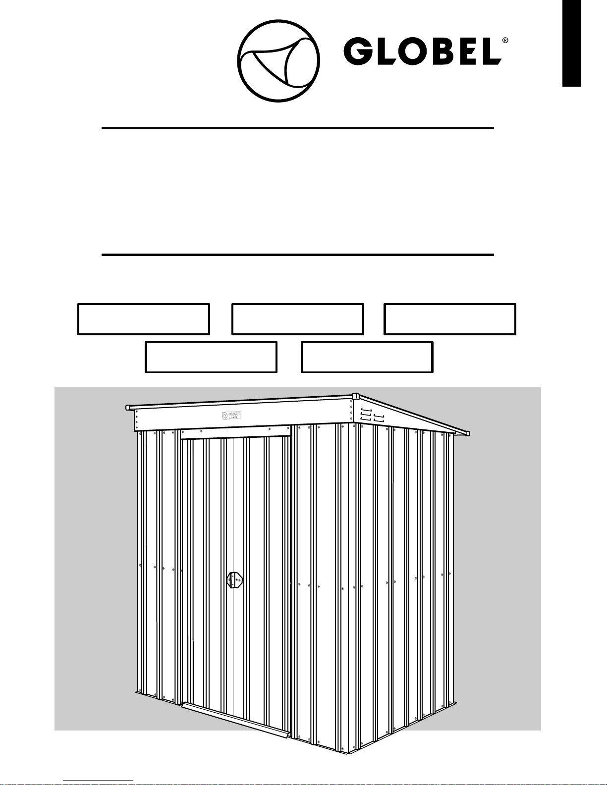
Check the labelling on the Parts Cartons to ensure you have the shed model you ordered, and the correct
number of Parts Cartons.
For simplicity, in most part, this manual illustrates the construction of a 6' wide x 4' deep garden shed,
with additional instructions for 5' and 8' wide garden sheds inserted where applicable.
TOOLS INFORMATION:
The tools you need are shown in the "TOOLS REQUIRED" section as all holes for screws and nuts and bolts are pre-drilled
(excluding one hole only, which will require a 3mm drill bit) you will only need a power screw driver or a cordless drill with
a magnetic Phillips-head tip to make the assembly quicker and easier.
Do not over-tighten self-tapping screws.
Nuts can be tightened by holding your finger on them as you tighten the bolt with the power screw driver -
no spanner needed.
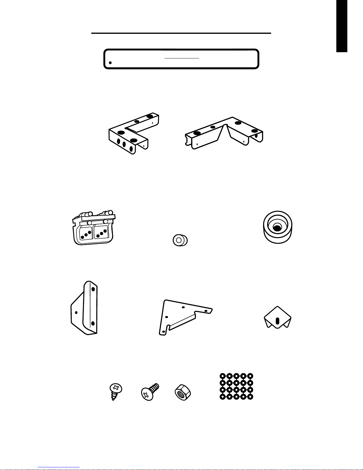
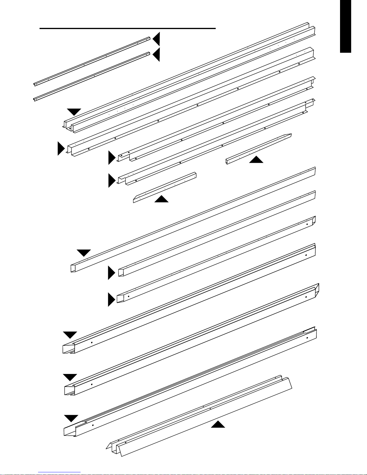
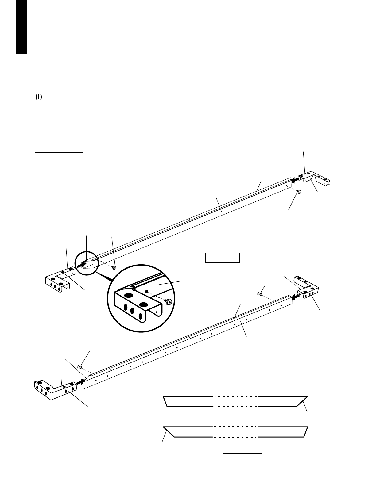
CHECK THE PARTS:
Before you start, separate and identify all the parts and hardware. (Refer to Parts List diagrams in the following pages).
WARNING: Edges are sharp - Handle with care - Using gloves is highly recommended.
WE RECOMMEND you get a second pair of hands to assist you with the assembly.
INSTALLATION ADVICE
Garden Shed Specifications
SHED TYPE / SIZE BASE DIMENSIONS
(Front x Sides mm) ROOF DIMENSIONS
(Front x Sides mm) WALL SHEET
HEIGHT
mm Front Back
OVERALL HEIGHT
mm DOOR OPENING
(Height x Width mm) No. CARTONS
(Weight Kg)
Size (Feet)Type
Double Sliding Doors 5 x 3 1400 x 820 1480 x 930 1780 1935 1700 x 590 1 (40)1785
Double Sliding Doors 6 x 3 1710 x 820 1800 x 930 1780 1935 1700 x 625 1 (43)1785
Double Sliding Doors 6 x 4 1710 x 1130 1800 x 1240 1780 1975 1700 x 625 1(50)1785
Double Sliding Doors 8 x 3 2340 x 820 2420 x 930 1780 1935 1700 x 1050 2 (55)1785
Double Sliding Doors 8 x 4 2340 x 1130 2420 x 1240 1780 1975 1700 x 1050 2 (60)1785
1
E N G L I S H