A
B
C-C
A
B
C C
Qty
Part
Number
DescriptionItem
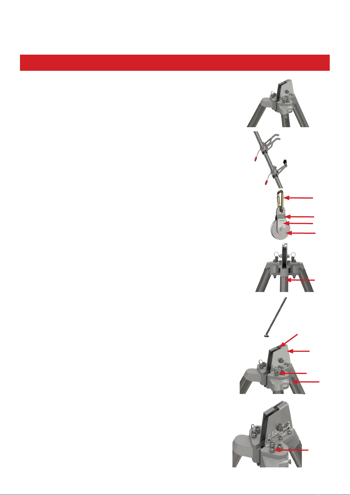
3200-12LOWER LEG
1
3200-18M4 X 8 CSK SCREW, SS5
3200-19M4 FORM A WASHER, SS6
3200-22RUBBER FOOT
7
3200-24M8 x 50 HEX HEAD BOLT, STAINLESS STEEL8
3200-34M8 NYLOC NUT, SS9
1210-03
Middle Head
10
1
210-04
Left Head
11
1
210-05Right Head12
2210-06LOCKING PIN ASSEMBLY13
2210-07M12 x 90 SOCKET HEAD CAP SCREW, BZP14
1
210-09
PULLEY
16
1
210-10Pulley Bush
17
1210-11
Pulley Bolt Sleeve
18
2210-12M12 x 50 SOCKET HEAD CAP SCREW, SS19
2210-15PULLEY BRACKET20
6210-16M8 x 16 BUTTON HEAD SCREW, SS21
1210-19ROPE GUIDE22
1210-20
Locking Ring
23
1
210-21M8 X 10 SET SCREW, STAINLESS STEEL24
1
210-22BALL SPRING PLUNGER25
1210-23
Sealing Cap
26
1210-24BOWNUT27
1
210-253MM x 30 SELLOC PIN, SS28
1
210-26M12 LARGE OD WASHER, SS29
3210-27M8 X 20 CSK SOCKET SCREW, SS30
1210-28
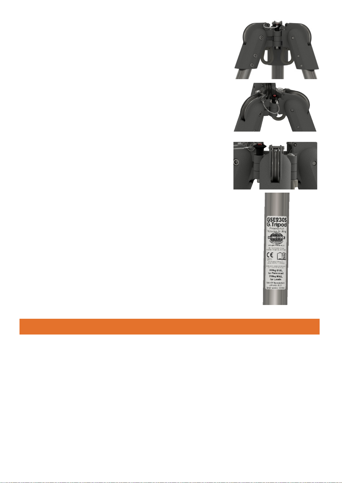
Identity Label
31
2210-29CE LABEL32
3210-32UPPER LEG33
6507-07M8 FORM B WASHER, SS34
2507-09M8 X 25 HEX HEAD SCREW, SS35
3507-40M12 NYLOC NUT, BZP36
2507-85BRASS PLATE HAMMER DRIVE37
6907-31M8 RECTANGLE SPRING WASHER, BZP38
7907-32M12 FORM A WASHER, SS39
3SA200LACLEG ADJUSTMENT CLIP
44
1
1
2
2
3
3
4
4
5
5
6
6
A A
B B
C C
D D
DO NOT SCALE
COPYRIGHT NOTE
THIS DRAWING REMAINS
THE PROPERTY OF
GLOBESTOCK LTD AND IS
SUBJECT TO COPYRIGHT.
IT CANNOT BE USED IN
PART OR WHOLE WITHOUT
WRITTEN PERMISSION
FROM GLOBESTOCK LTD.
1.6
ALL DIMENSIONS IN mm
3rd ANGLE PROJECTION
SURFACE FINISH
UNLESS OTHERWISE STATED
BYDATE
LINEAR AND ANGULAR TOLERANCES
NO DECIMAL PLACES `0.5
1 DECIMAL PLACE `0.10
2 DECIMAL PLACES `0.05
GEOMETRIC TOLERANCES
MACHINING `0.10
FABRICATION `0.25
CHANGES TO DRAWINGREV 18/12/2018
DATE
11
GSE 210-00
DRAWN BY
(: +44 1691 654 966
*: info@globestock.co.uk
:: www.globestock.co.uk
Mile Oak Industrial Estate,
Maesbury Road,
Shropshire,
SY10 8GA
of
SHEET 005
Simon Lewis
PART NUMBER
DESCRIPTION
N/A
MATERIAL
G.Tripod General Assembly
SHEET
of
GSE 210-00 1 1 005
001 09-04-01 First issue. DS
1
44
6
7
9
10
11
12
13
14
16
18
19
17
20
21
22
23
24
25
27
29
31
32
33
35
36
37
38
39
002 08-02-06 Bracket screw added, upper leg part number change. DJW
003 24-04-07 Part number change, 507-09 was 707-09. PAS
004 08-05-15 Part number change, 507-09 was 707-09. DJW
005 18-12-18 Assembly updated in line with current build. SPL